Before we begin, let me say a few things about this website. I do not go out of my way to publicize the URL, other than a few random posts on electronics forums over the years. So if you got here, you probably are very good at hunting down test equipment information. This site was started many years ago as a simple portable way for me to keep track of my test equipment and the repairs I made. I wrote it in an irreverent style because I was the only one who was ever going to see it. But as I gave the address to a few friends and colleagues, it became clear that my audience was larger than just one, and they seemed to enjoy my commentary on the equipment. Now there are probably several hundred people that occasionally visit this website and I am sure that some do not like my style. Sorry.
WHAT'S NEW? LATEST ADDITIONS TO THIS WEBSITE:
Sencore FC45 (March, 2024)
HP 1740A (March, 2024)
Pacific Measurements 1034A (February, 2024)
HP 6205C (January, 2024)
Adret 2230A (December, 2023)
Racal 9083N (November, 2023)
Wavetek 154 (see the "It's Dead, Jim" section) (November, 2023)
HP 8013B (October, 2023)
Hitachi VC-7104 (September, 2023)
Note: New/modified repair notes are not individually listed as latest additions since they occur too frequently to keep track of them all!
---------------------------------------------------------
This is my (ever changing) collection of old test equipment. Most of the collection dates from what I consider to be the peak period in repairable semiconductor based test equipment, 1970 to 1990. Manufacturers like HP and Tektronix usually prepared exquisite service manuals, something unheard of today. On the other hand, they sometimes used custom ICs that are only very rarely now available. But compared to most equipment made after 1990, for which "repair" means "board replacement," these earlier pieces offer a fun and usually solvable challenge. Almost every piece in the collection that I received broken has been successfully repaired and restored to original specifications.
There are currently 467 pieces in my collection. But that's likely to change tomorrow. Maybe even in the time it takes you to read this page. HP equipment makes up the largest subset by far (> 150 pieces). Other major vendors include Tektronix, Fluke and Wavetek. Each major manufacturer had their own ways of doing things which often times were strikingly unique. But for my money (which it is), I am an HP connoisseur and simply can't bear to let one of their pieces perish if the price is right.
Virtually all of the pieces were bought on eBay. My constraint is usually to pay no more than 2% of the latest catalog MSRP. Sticking to this constraint means that the items are usually broken. But that's the whole point, isn't it? The pieces that were not bought were usually given to me by friends and relatives. A couple of pieces were literally picked out of the garbage can.
Those pieces that were received in some state of disrepair (something more than simple dirty switches/pots or misalignments) and were repaired by me have some brief repair notes in blue below their descriptions. Well, they started out as brief. As I collected more equipment, the repair descriptions became more and more verbose and described much of the repair journey. At the bottom of this page are some general comments on repair.
While the descriptions and repair notes are accurate, each reflects my state of mind and state of equipment at the time I wrote it. So often times I make comments, such as "the best scope I own," which may no longer be true. I haven't gone back and reworked various descriptions. Life is too short.
I've said nothing about operation and service manuals. For the most part, these are necessary in order to repair things. Not mandatory, and I've certainly fixed a lot of stuff without them mainly by visual inspection. To paraphrase Yogi Berra, "You can see a lot by looking." But finding manuals is almost as much fun as finding the equipment. Some can be had for free, some can be had for a few bucks, and some can be had from retail manual dealers. It is not at all uncommon to spend more for the manual than I did for the piece of equipment. Such is life. The manual status is provided at the end of each unit's description:
(OM) - Original hard copy manual purchased from a dealer
(PDF) - PDF file obtained for free
($CD) - Soft copy manual purchased and delivered via CD or download
(---) - Don't have
Almost all the (PDF) and ($CD) manuals were printed out locally. Several of the manuals I purchased were later found online for free. What, you think life is fair?
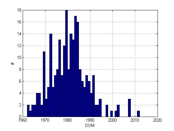
Here is a histogram of the manufacture dates of the pieces listed on this page. Most of these dates were gleaned from the date codes of the ICs inside. One often cannot rely upon date codes embedded in serial numbers (sometimes that number refers to the design rev date, not the manufacture date).
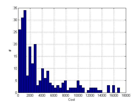
And here is a histogram of MSRPs up to about $20,000. I have a few items more expensive, but they weren't included in this plot. Using the latest catalog price is somewhat iffy since some manufacturers, in particular HP, often skyrocketed their prices right before they discontinued an item. Whether this cost increase was due to the difficulty in obtaining parts, or whether it was used as an inducement to buy the replacement model, isn't exactly clear to me.
Finally, everyone is entitled to their own opinion. But on this web page, everyone is entitled to MY own opinion! So I have given each piece in the current collection a letter grade loosely based upon the following criteria:
I would have also included my cost in the above list, but I haven't been keeping records. If I had to, I would guess that my average cost is about $50 per piece. Just a guess.
Also scattered about are several "bonus rants." These pontifications usually occur when a piece frustrates me to the point of wanting to toss it across my basement or when a manufacturer consistently seems to be doing something dumb. Earning a rant does not necessarily imply a bad grade, however.
- Build quality (mechanical, electrical and ease of repair)
- Performance and/or specifications
- Ease of use
- Uniqueness (does every manufacturer make one or is there some functionality unique to this piece?)
- Innovation (at the time of manufacture, did the piece incorporate major design innovations?)
I would have also included my cost in the above list, but I haven't been keeping records. If I had to, I would guess that my average cost is about $50 per piece. Just a guess.
Also scattered about are several "bonus rants." These pontifications usually occur when a piece frustrates me to the point of wanting to toss it across my basement or when a manufacturer consistently seems to be doing something dumb. Earning a rant does not necessarily imply a bad grade, however.

Here is a histogram of the grades using the standard 0-4 GPA mapping. Like the current situation in higher education, it reveals some grade inflation. The average of the grades is 3.14 - a solid "B." This chart was made at about piece #170. I haven't bothered to update it since and I doubt that the overall average would change much anyway.
If you feel that you disagree with a piece's letter grade, I suggest you remember what happened to you when you went up to the professor after class and asked that your grade be changed. Maybe you never did that, but I once went up to the professor in college after receiving a 99 on a math exam. I looked all through the exam paper for the stupid algebra mistake I must have made to cost me one point, but there wasn't a red mark anywhere to be found. So I asked the professor why I got a 99 instead of 100. His reply was simply, "I don't give 100s."
I know what you are thinking - where does he put all this stuff? Well, believe it or not, it all fits in a small corner of my basement. But that means I basically have to stack stuff from floor to ceiling. Most of the stuff I use frequently is plugged into AC and near my (small) work area. The outlying pieces generally are not plugged in, but things are arranged so I can easily get to the back to plug in power cords.
AND NOW, HERE IS THE COLLECTION!
Instructions: Scroll Down, Click on Pictures to Expand.
Like the Energizer Bunny, just keep going and going...
A : AC/DC, Adret, Advantest, Associated Research, Atten, Audiolab, AUL
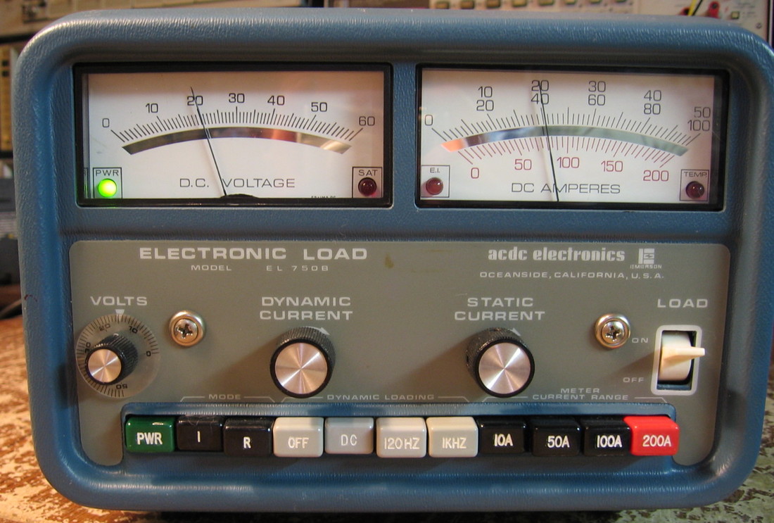
AC DC EL750B: Dynamic DC electronic load. Will handle 750 watts (up to 50V and up to 150A). Can set two levels for 120 Hz or 1 kHz dynamic switching. Has I and R modes but no V mode like the more expensive units. My only complaint is that the smallest range is 10A, so adjusting the load from very small currents (e.g., batteries) is hard. This unit runs very cool - I've dumped 100 watts into it for hours and could feel no heat anywhere. (OM) Grade: B+
This piece came to me with a defective P/S which was due to an open AC transformer - a very rare situation indeed. If that wasn't enough, three of the sixteen load transistors were blown (one had a hole burned through the TO-3 case). And the voltmeter didn't work either. I gutted the P/S and built a new one, replaced all sixteen load transistors, exchanged the old voltmeter mechanism with a new one (keeping the existing meter face). I also replaced the load adjust pot with a three turn pot for finer control.
This piece came to me with a defective P/S which was due to an open AC transformer - a very rare situation indeed. If that wasn't enough, three of the sixteen load transistors were blown (one had a hole burned through the TO-3 case). And the voltmeter didn't work either. I gutted the P/S and built a new one, replaced all sixteen load transistors, exchanged the old voltmeter mechanism with a new one (keeping the existing meter face). I also replaced the load adjust pot with a three turn pot for finer control.
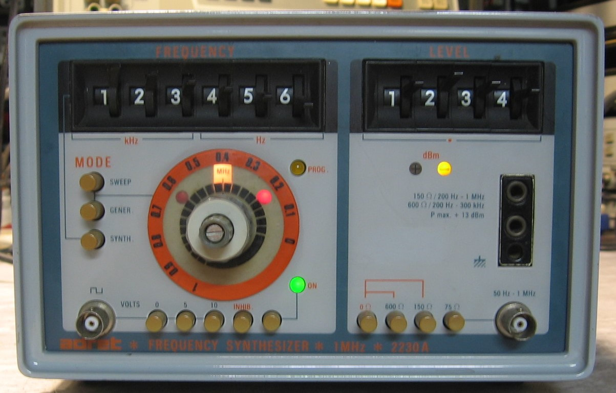
Adret 2230A: This is a curious 1 MHz synthesizer with 1 Hz resolution and amplitudes from about +20 dBm to -70 dBm. You will notice that the synthesizer has thumbwheel switches for frequency (and amplitude) and also a big knob underneath. The synthesizer can be put in "generate" mode and the output frequency is controlled by the knob (from 0 to 1 MHz). When the frequency dialed in from the knob agrees with whatever is set on the thumbwheel switches, the "error" LEDs adjacent to the knob slowly blink (otherwise a solid LED shows whether you are high or low). The 2230A can also be put in sweep mode controllable by an external DC voltage. Otherwise, the basic controls are a bid odd as you can tell from the picture and I won't elaborate further here. I only have one other Adret piece (CS-201SB) and I have to say that at least in the late 1970's, early 1980's, Adret was producing equipment just as good as any of the (worldwide) test equipment manufacturers. (OM) Grade: A-
This piece was bought for $40 shipped including the paper op/service manual. That's pretty good as shipping alone had to cost the seller at least $20. When received (in advertised condition unknown), it powered on but produced no output. A few minutes later, I heard a pop and the piece went dead, drawing no power from the AC line. The main fuse had blown and the piece was wafting the unmistaken smell of a burnt tantalum capacitor. Opening up the piece, I saw one tantalum that had half severely discolored black. As I went to remove and replace it, I noticed that it wasn't that capacitor that burned. Nope, it was the adjacent tantalum that exploded and was now completely missing. So two new capacitors were installed and the piece sprang to life. Everything seemed OK, but then I noticed that, particularly when using the 100 kHz digit switch, the output frequency would be way off. Moving the switch to a different frequency and then quickly returning to the same selection produced the right output. Since the main operating circuit involves a VCO/PLL, it seemed to me like a somewhat familiar case of the VCO being slightly off frequency and not in the capture range of the PLL. A slight tweak of an adjustable transformer adjacent to the VCO circuitry quickly fixed the problem. The only other thing wrong was that the back panel 1 MHz output reference signal was absent. This was traced to an open secondary of a transformer. The transformer in the parts list was marked "38/6, 33 uH," and I interpreted that as 38:6 turns ratio and a 33 uH primary. I found something close from Coilcraft for $3 and installed it a few inches from where it should have been (it was too big to fit in the original spot). Problem solved. What was even stranger was that the faulty transformer tested in-circuit short on the primary (as expected) and open on the secondary. But when I pulled it out, the primary also tested open. There was a solder-blob short between two traces about 1/4 inch from the primary. The solder looked original to the unit, so there is no way that the 1 MHz would appear on the output even if the transformer was good. I guess it was an original manufacturing error. Finally, the spec says -55 dBc for harmonics, but I'm only getting -50 dBc. There is no adjustment information in the manual, so I'm not about to start adjusting various transformers to see if I can tweak it.
This piece was bought for $40 shipped including the paper op/service manual. That's pretty good as shipping alone had to cost the seller at least $20. When received (in advertised condition unknown), it powered on but produced no output. A few minutes later, I heard a pop and the piece went dead, drawing no power from the AC line. The main fuse had blown and the piece was wafting the unmistaken smell of a burnt tantalum capacitor. Opening up the piece, I saw one tantalum that had half severely discolored black. As I went to remove and replace it, I noticed that it wasn't that capacitor that burned. Nope, it was the adjacent tantalum that exploded and was now completely missing. So two new capacitors were installed and the piece sprang to life. Everything seemed OK, but then I noticed that, particularly when using the 100 kHz digit switch, the output frequency would be way off. Moving the switch to a different frequency and then quickly returning to the same selection produced the right output. Since the main operating circuit involves a VCO/PLL, it seemed to me like a somewhat familiar case of the VCO being slightly off frequency and not in the capture range of the PLL. A slight tweak of an adjustable transformer adjacent to the VCO circuitry quickly fixed the problem. The only other thing wrong was that the back panel 1 MHz output reference signal was absent. This was traced to an open secondary of a transformer. The transformer in the parts list was marked "38/6, 33 uH," and I interpreted that as 38:6 turns ratio and a 33 uH primary. I found something close from Coilcraft for $3 and installed it a few inches from where it should have been (it was too big to fit in the original spot). Problem solved. What was even stranger was that the faulty transformer tested in-circuit short on the primary (as expected) and open on the secondary. But when I pulled it out, the primary also tested open. There was a solder-blob short between two traces about 1/4 inch from the primary. The solder looked original to the unit, so there is no way that the 1 MHz would appear on the output even if the transformer was good. I guess it was an original manufacturing error. Finally, the spec says -55 dBc for harmonics, but I'm only getting -50 dBc. There is no adjustment information in the manual, so I'm not about to start adjusting various transformers to see if I can tweak it.
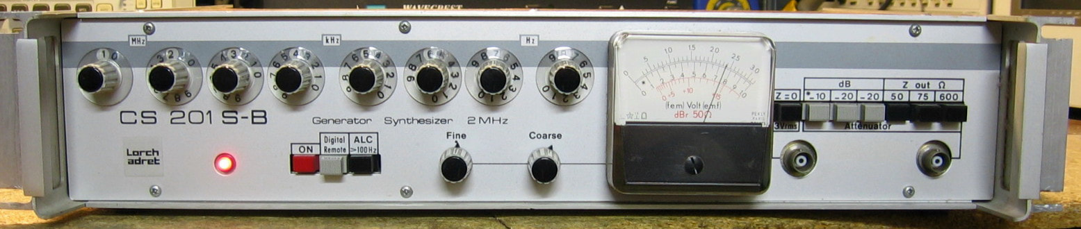
Adret CS-201SB: 2 MHz synthesizer. This was a replacement piece for the broken Adret 201 described in detail in the "It's Dead, Jim" section near the bottom of this web page. The "SB" model omits the AM/FM modulation capability, but does have more precise control over the amplitude. It also works with the Adret 211 external control box also described below. I bought this with the idea of using the parts to fix the original 201. But it works fine right out of the box, so we will stay with this one. While the original one had 1966 date codes on some of the parts, this newer SB version has 1986 date codes. Adret also cleaned up the layout quite a bit. From what I can ascertain, Adret was well known for its synthesizers 50 years ago, and I must confess that their early pieces were way ahead of HP and Tektronix at that time. (PDF) Grade: A-
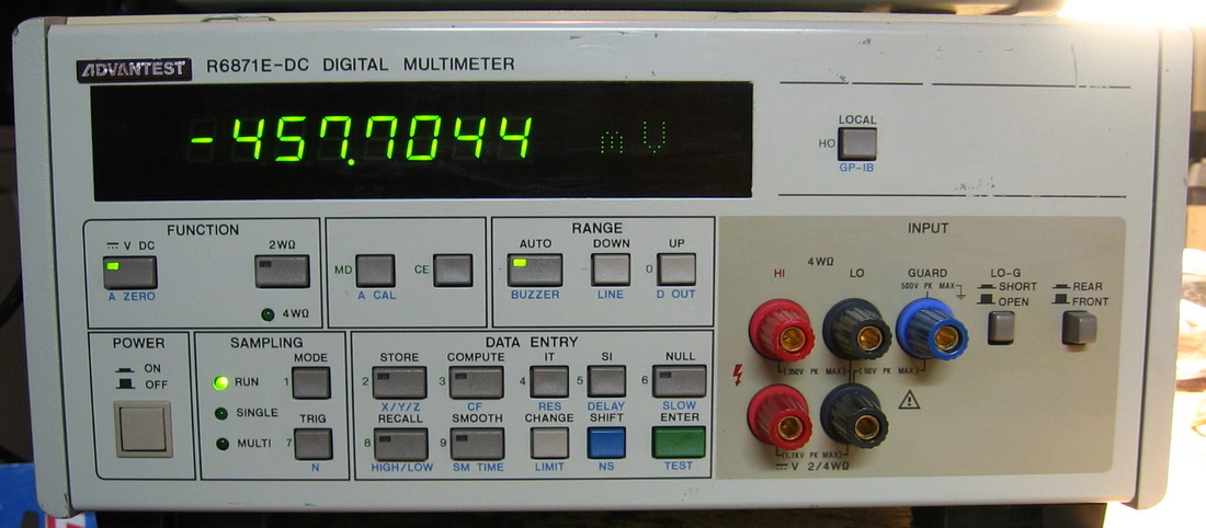
Advantest R6871E-DC: 7-1/2 precision DMM from the Japanese. This is a real sleeper. I would put it on par with any of my top HP, Fluke or Datron DMMs. Advantest made a full 6871E model (DCV, ACV, DCI, ACI, ohms) and the more modest 6871E-DC model which only does DCV and ohms. Unfortunately, mine is the latter, but if I ever see a good price on the full model, I won't hesitate to buy it. The best-range 24 hour DCV and ohms specs are about 0.0012% and 0.002% respectively at 24 hours, rising to 0.0037% and 0.006% at 180 days. Calibration is via software controlled by the front panel. The user gets much more control over sampling interval, number of power-line cycles and averaging than is usually found in DMMs. There is also a small set of math and statistic functions as well as auto-zero and auto-cal functions. The only downside to this meter is that it is HUGE - 12" x 6" x 18". Whereas a lot of non-rackmountable DMMs, such as the Advantest TR6845 and TR6857 models shown below, could be considered portable and shuffled around the lab bench, the R6871E is much too large for that. All in all, a fantastic buy at $50. (PDF) Grade: A.
I took somewhat of a gamble on this because there is no service manual available (and maybe no service manual in existence). The seller said, "When unit powers on, no lights on display." But the back panel showed the thing set for 220 VAC, so no wonder. The operator's manual was obtainable on-line and said that the AC line voltage is set at the factory at the time of purchase (separate options for 100, 120, 200, 220 or 240 VAC). I gambled that I could reset the line voltage to 120 VAC as my other two Advantest DMMs had clearly labeled jumpers for that on the circuit board. But when I opened up the R6871E-DC, all I found were six wires going to a six-pin terminal strip with a jumper between pins 2 and 4. I took a guess that that was the two primaries run in series, so I jumpered 1-4 and 2-5 to (hopefully) put the primaries in parallel. I have no clue what pins 3 and 6 are for. The piece sprang to life, passed all tests and calibrated nicely. I've since found a picture of the terminal strip from an eevblog user who posted teardown pictures and his 120 VAC unit was jumpered the way I guessed.
I took somewhat of a gamble on this because there is no service manual available (and maybe no service manual in existence). The seller said, "When unit powers on, no lights on display." But the back panel showed the thing set for 220 VAC, so no wonder. The operator's manual was obtainable on-line and said that the AC line voltage is set at the factory at the time of purchase (separate options for 100, 120, 200, 220 or 240 VAC). I gambled that I could reset the line voltage to 120 VAC as my other two Advantest DMMs had clearly labeled jumpers for that on the circuit board. But when I opened up the R6871E-DC, all I found were six wires going to a six-pin terminal strip with a jumper between pins 2 and 4. I took a guess that that was the two primaries run in series, so I jumpered 1-4 and 2-5 to (hopefully) put the primaries in parallel. I have no clue what pins 3 and 6 are for. The piece sprang to life, passed all tests and calibrated nicely. I've since found a picture of the terminal strip from an eevblog user who posted teardown pictures and his 120 VAC unit was jumpered the way I guessed.

Advantest TR6845: At least this unit has a continuity tester. Very easy to use, pretty accurate (although not as good as the HP units). One of two. The build quality on the TR6845 (and the TR6847 below) is very good. Don't let the cheap plastic look fool you, Advantest knew what they were doing. (---) Grade: B
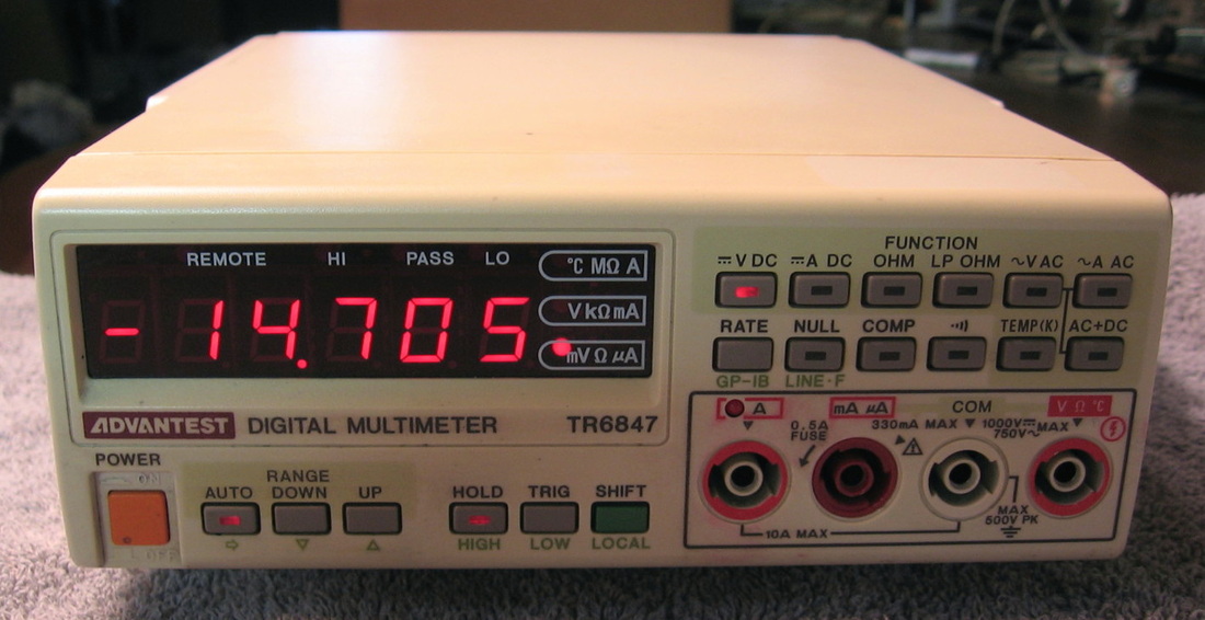
Advantest TR6847: A cute DMM that for some reason does not have a continuity tester (actually it does by combining the ohms function and the "beep" function). Takes readings ten times faster than the TR6845 and is twice as accurate. Presumably Advantest made a slew of DMMs at various price points. (---) Grade: B
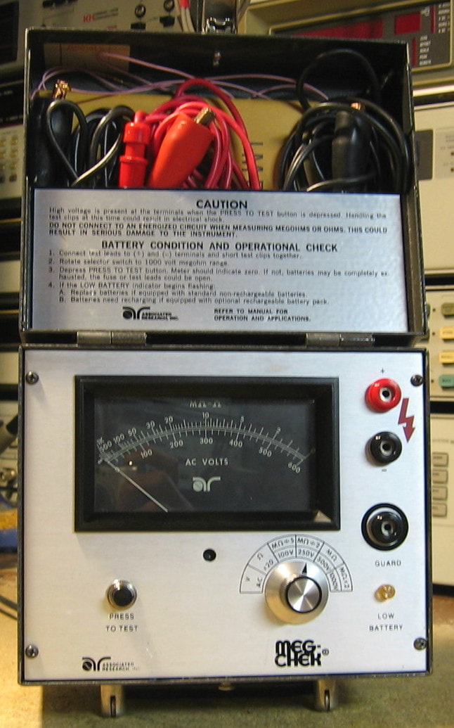
Associated Research 2100A: High resistance meter. This is a somewhat odd megohmmeter that measures in four ranges, 200M, 500M, 1000M and 2000M, using a maximum of 50 uA at 100, 250, 500 and 1000 VDC respectively. It also has a 20K range (5 volt source) and a 600 VAC range for some strange reason. The unit has a tray for 8 D-cell batteries and a jack for a 12 VDC external supply. It has a nice sturdy metal hinged case and came complete with three test leads, the operation manual and original paperwork. This thing is basically a step-up switching power supply and a bunch of range resistors, but has far more componentry than I would have expected (pwm modulator IC, quad comparator, 555 timer, etc.). Kind of limited, especially when you compare it to my HP 4329A High Resistance Meter, but for ten bucks, who cares? (OM) Grade: B
This piece was received in "condition unknown" and after I installed batteries, the meter didn't move at all on any setting. And that was because the meter glass had worked free and was pressing against the faceplate trapping the needle. After I glued the glass back, the piece gave approximately the correct readings. Full scale (zero ohms) on all ranges was a bit low, but there were five 10-turn pots inside that corrected that on the five resistance ranges. There are also three other pots that must adjust something, but I don't know what. When I hooked the test leads up to my Fluke 8502A DMM, I only measured 83.6, 167, 250 and 334 VDC coming out of the unit on the 100, 250, 500 and 1000 V ranges. This had me perplexed for a while. Seems as though the 2100A will throttle the output voltage and current back from the maximum value if the resistance under test is low. And since the Fluke 8502A DMM only has a 10 meg input impedance on the 1000 VDC scale, I guess that was what happened. In order to verify that the 2100A is capable of outputting 1000 VDC, I cut a 5/8" piece of cardboard Q-tip which I then measured to be about 1 gigaohm with my HP 4329A High Resistance Meter. Put that in series with the 8502A DMM which gave me about a 100:1 voltage divider. I then measured the divided voltage and it was about 10 volts which proved the 2100A was outputting the maximum voltage.
This piece was received in "condition unknown" and after I installed batteries, the meter didn't move at all on any setting. And that was because the meter glass had worked free and was pressing against the faceplate trapping the needle. After I glued the glass back, the piece gave approximately the correct readings. Full scale (zero ohms) on all ranges was a bit low, but there were five 10-turn pots inside that corrected that on the five resistance ranges. There are also three other pots that must adjust something, but I don't know what. When I hooked the test leads up to my Fluke 8502A DMM, I only measured 83.6, 167, 250 and 334 VDC coming out of the unit on the 100, 250, 500 and 1000 V ranges. This had me perplexed for a while. Seems as though the 2100A will throttle the output voltage and current back from the maximum value if the resistance under test is low. And since the Fluke 8502A DMM only has a 10 meg input impedance on the 1000 VDC scale, I guess that was what happened. In order to verify that the 2100A is capable of outputting 1000 VDC, I cut a 5/8" piece of cardboard Q-tip which I then measured to be about 1 gigaohm with my HP 4329A High Resistance Meter. Put that in series with the 8502A DMM which gave me about a 100:1 voltage divider. I then measured the divided voltage and it was about 10 volts which proved the 2100A was outputting the maximum voltage.

Atten 5011: DC-1.1 GHz spectrum analyzer. Cheap Chinese knockoff, but useful for a quick survey or to check harmonics of signal generators and the like. Very limited selection of two resolution bandwidths plus a drift of 100 kHz in one hour. This really is a poor man's spectrum analyzer. It's one of the very few pieces that I bought new and I've been disappointed with it ever since. Typical Chinese construction using low grade parts, poor board layouts, poor mechanicals, etc. Those viewing this page may note that there are very few spectrum analyzers listed. For some inexplicable reason, the eBay prices on used spectrum analyzers are proportionally way out of line compared to just about any other class of equipment. (OM) Grade: C-
Postscript: Not that I have any use for this piece given my other spectrum analyzers, but I recently turned it on after a few years of dormancy just to see if it still worked. It didn't. In fact, the CRT was dark (although the filament was glowing) and the display and controls were frozen at the upper frequency limit. I gave it the visual once-over, but everything looked fine. By some quirk, the service manual for the re-branded Hameg HM5011 was on the web and if it weren't for that, I would have given up. The immediate problem was that the 12V line was shorted. This serves as the reference for -12V and for the voltages that are developed to supply the CRT, so no wonder everything was hosed. I pulled the P/S output line and the short was confined to the P/S. The pass transistor output has two capacitors hung off the output and I was sure it had to be one of those, since nothing else had a clear path (without a resistor) to ground. But it turned out to be the thermal insulator for the pass transistor that had failed, shorting the case to ground. After that was fixed, all the controls/displays went back to normal, except that the CRT was still dark. The -2000V going into the CRT board from the P/S was fine, so I pulled the CRT board and took a look. There was a 4N35 photo-transistor in a socket and when I pulled that and put it on the component transistor, the diode was OK but the transistor was toast. I managed to find an MCT2E in the junkbox and threw that in. Whoopee, the CRT came up just fine. There is also an LED hung off the base of the photo-transistor which is unlit and my guess is that opened up as well when the photo-transistor blew. I'll test/replace it one of these days. Until then, back on the pile the 5011 goes for a few more years.
Postscript: Not that I have any use for this piece given my other spectrum analyzers, but I recently turned it on after a few years of dormancy just to see if it still worked. It didn't. In fact, the CRT was dark (although the filament was glowing) and the display and controls were frozen at the upper frequency limit. I gave it the visual once-over, but everything looked fine. By some quirk, the service manual for the re-branded Hameg HM5011 was on the web and if it weren't for that, I would have given up. The immediate problem was that the 12V line was shorted. This serves as the reference for -12V and for the voltages that are developed to supply the CRT, so no wonder everything was hosed. I pulled the P/S output line and the short was confined to the P/S. The pass transistor output has two capacitors hung off the output and I was sure it had to be one of those, since nothing else had a clear path (without a resistor) to ground. But it turned out to be the thermal insulator for the pass transistor that had failed, shorting the case to ground. After that was fixed, all the controls/displays went back to normal, except that the CRT was still dark. The -2000V going into the CRT board from the P/S was fine, so I pulled the CRT board and took a look. There was a 4N35 photo-transistor in a socket and when I pulled that and put it on the component transistor, the diode was OK but the transistor was toast. I managed to find an MCT2E in the junkbox and threw that in. Whoopee, the CRT came up just fine. There is also an LED hung off the base of the photo-transistor which is unlit and my guess is that opened up as well when the photo-transistor blew. I'll test/replace it one of these days. Until then, back on the pile the 5011 goes for a few more years.
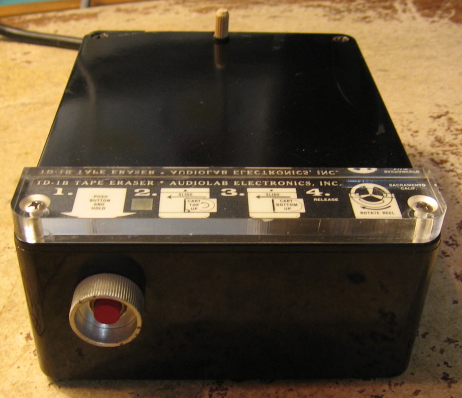
Audiolab TD-1B: "The Audiolab TD-1B Professional Tape Degausser is designed for the demanding broadcast industry," so sayeth the datasheet. I guess maybe in 1970 that was true. I bought this during my tape recorder "phase", e.g., the Racal 14DS and HP 3964A. Take an 8 lb 115V/8A transformer, throw it in a pretty Bakelite box with a switch and voila. Does 1500 Gauss. If you know what that means, you've really got too much time on your hands. (--) Grade: B-
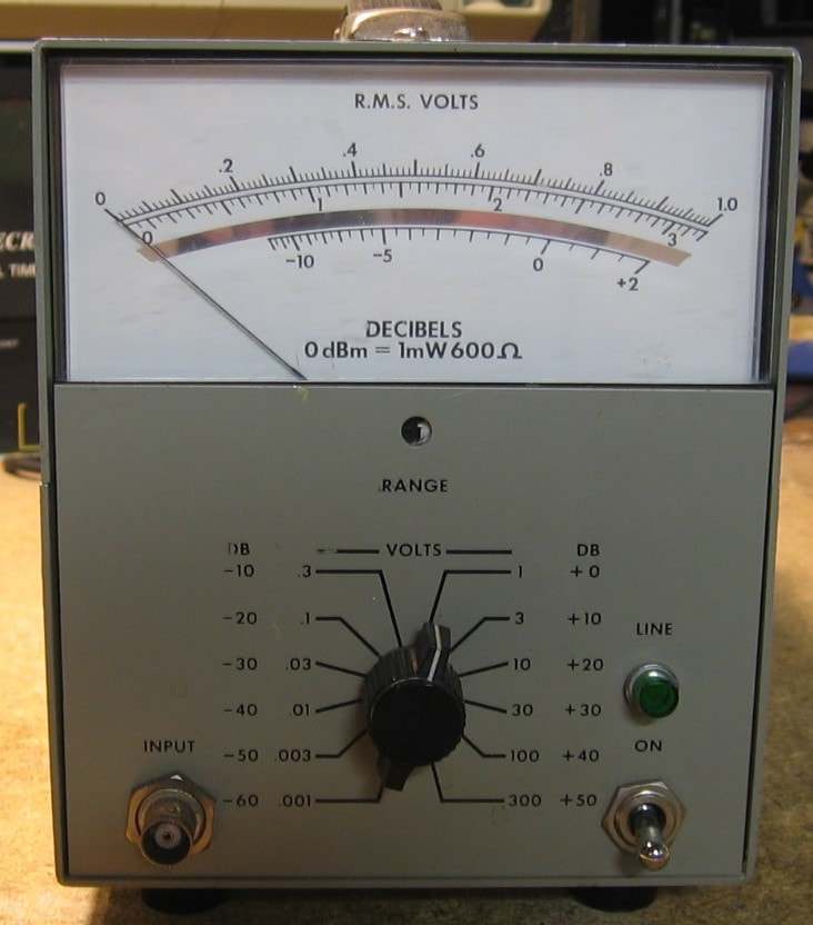
AUL Instruments ME-30F/U: AC Voltmeter. This one is somewhat of a mystery. There is a label on the bottom that says ME-30F/U, but it looks like someone cut this out from somewhere (it is not quite rectangular) and taped it the cabinet. Information on the ME-30F/U is nowhere to be found, but the front and rear panels look suspiciously like an HP 400E AC voltmeter. In fact, upon closer examination, the circuit board is 99% identical to the HP 400E, even down to the component numbering. There are two extra adjustment pots, the meter and case are obviously different, the P/S is adjusted nominally to 22 VDC rather than the 26 VDC in the HP 400E, and the internal bias is 8 VDC instead of 10 VDC, but otherwise it is an HP 400E. So I have no idea what is going on - why did the military commission this piece instead of simply buying an HP 400E? Spec-wise, it does frequencies up to 10 MHz and has ranges from 1 mV to 300 V full scale. (---) Grade: B+
The only damage when received was the AC power jack, the old-style HP type, which was all burnt up and one of the pins was missing. The jack was replaced with the more modern type. I tweaked the adjustment pots, but the thing already was close to perfect.
The only damage when received was the AC power jack, the old-style HP type, which was all burnt up and one of the pins was missing. The jack was replaced with the more modern type. I tweaked the adjustment pots, but the thing already was close to perfect.
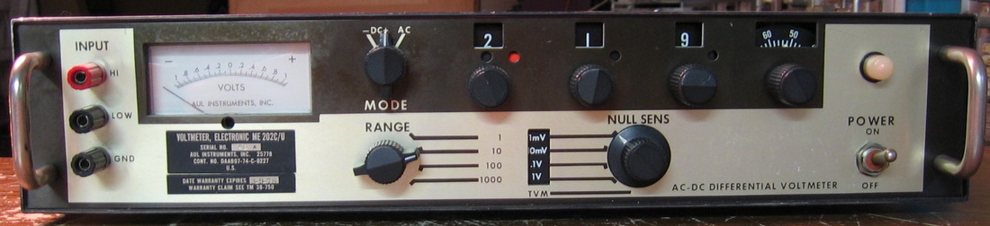
AUL Instruments ME-202B: Old school differential voltmeter. This one is about 1 mV off. This piece was one of those <$10 junkers that looked like fun. Of course, any decent digital voltmeter (HP 3455, 3456, 3490, 3468) will outperform the ME-202, but I guess nulling voltmeters had their place years before. (PDF) Grade: C-
This was so jostled in shipping that the boards inside had broken free of their standoffs. Many wires had also broken clean off. Without a schematic, I took a guess and glued all the boards down and rewired everything. Seems to work just fine now.
Postscript: I hadn't used this piece in so many years that when I finally did, it was out of calibration. Attempting to recalibrate revealed a problem in one of the ten-turn adjustment pots, so it was replaced.
B : Ballantine, BBC, Beco, Biddle Gray, Biomation, BK Precision, Boonton
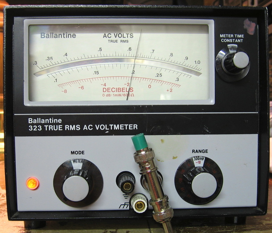
Ballantine 323: True RMS AC voltmeter from <2 Hz to >30 MHz, 0.3 uV to 300 V full scale. Real annoying recessed BNC jack on front panel. Comparable to HP 3400A. Whereas the HP 3400A uses a thermocouple, the Ballantine 323 uses the non-linearities of diodes to measure the RMS voltage. Completely different design, but comparable performance. Ballantine made several variants of this meter and the service manual is very confusing. (OM) Grade: B+
Gotta love this one. Some idiot had rotated one of the wafers of the multi-wafer switch 180 degrees. Took a while to find this error since who would have ever thought this could happen. After this was fixed, the unit was still intermittent. The fault was traced to a loose connection internal to the meter case. Who would have ever thought this could happen either.
Gotta love this one. Some idiot had rotated one of the wafers of the multi-wafer switch 180 degrees. Took a while to find this error since who would have ever thought this could happen. After this was fixed, the unit was still intermittent. The fault was traced to a loose connection internal to the meter case. Who would have ever thought this could happen either.
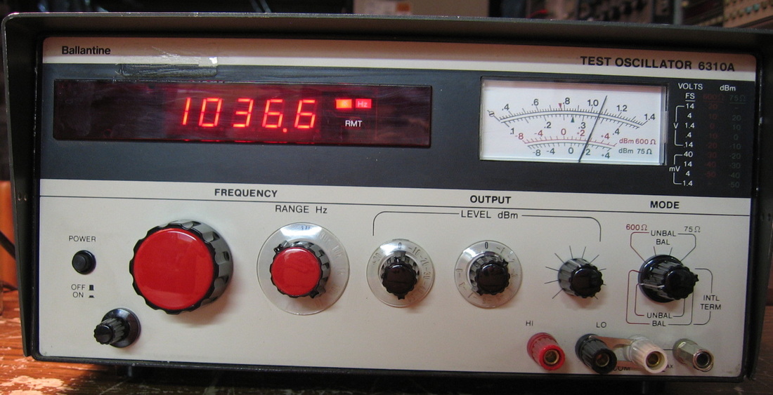
Ballantine 6310A: Basic 0-1.2 MHz sine wave generator, <0.1% distortion, 600/75, balanced/unbalanced, internal/external terminated, precise amplitude control. I don't know why the world needed yet another oscillator, but Ballantine seemed to think it did. I can't think of too many reasons why I would ever use this piece as it is simply boring. Unfortunately, I have never come across the service manual anywhere. (---) Grade: C
One of those mysteries of life. Although the unit basically worked, there was some strange distortion, especially on startup. At least my solution was to tie one of the unused IC pins to ground rather than leave it open like the idiots who designed the unit did.
One of those mysteries of life. Although the unit basically worked, there was some strange distortion, especially on startup. At least my solution was to tie one of the unused IC pins to ground rather than leave it open like the idiots who designed the unit did.
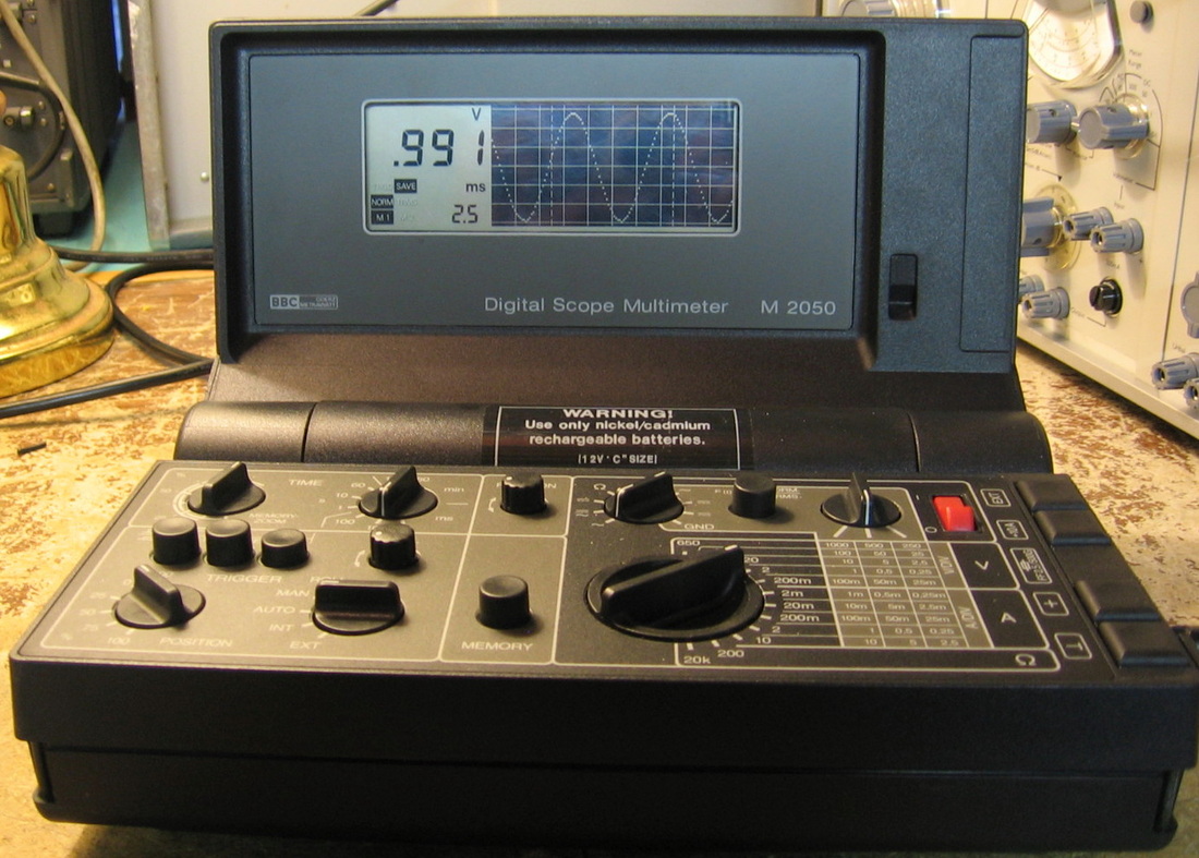
BBC M2050: Digital Scope Multimeter. A (very) poor man's version of the Fluke Scopemeter. It is a scope. It is a meter. It is a very limited scope. It is a very limited meter. For instance, the scope time base only goes down to 0.025 msec/div and the multimeter resistance tops out at 20K. Has the ability to scroll the scope up to 60 minutes and also has two memories and the ability to zoom through them. AC and DC coupling, different triggering options. Seems accurate from about 10 to 40 kHz. Not quite sure what they were thinking. But you have to admit, it is cute. And at seven bucks, how could I resist? (---) Grade: B
The four NiCd C-cells were still inside and for once they weren't leaking. Put regular alkaline batteries in, despite the warning label, because I don't have the charger. I don't know what kind of charger to use anyway seeing as I can find out absolutely nothing about this unit.
The four NiCd C-cells were still inside and for once they weren't leaking. Put regular alkaline batteries in, despite the warning label, because I don't have the charger. I don't know what kind of charger to use anyway seeing as I can find out absolutely nothing about this unit.
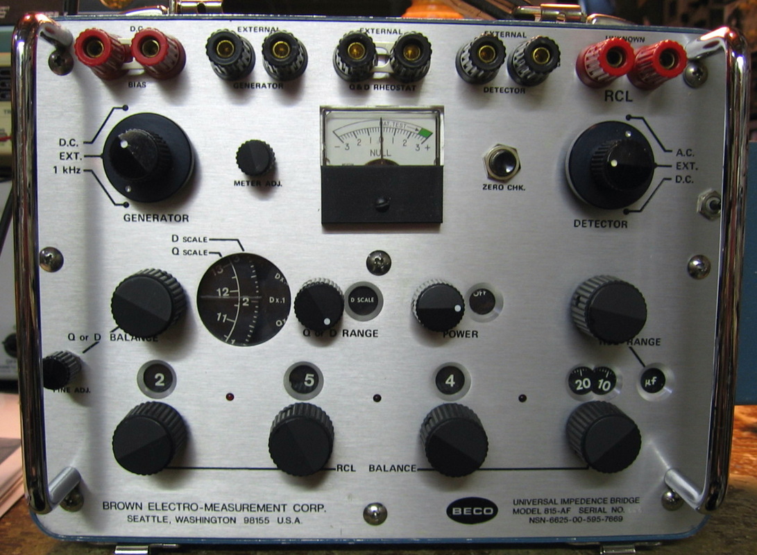
Beco 815-AF: Universal bridge similar to the early GenRad units, except GenRad knew how to spell the word "impedance," not "impedence." Good up to 1000 uF and will null at a resolution of about 0.1 pF on the lowest scale. One of two units. Fixed one, used the other for parts. Rumor has it that the Military needed impedance bridges and BECO managed to get around some patent infringements. Like all manually controlled bridges, it helps to know approximately what the answer is before you start. But the thing does do what it is supposed to. Has a very funky AC adapter that clips onto the side panel. BECO really intended it to be run on batteries. (---) Grade: C-
No repair really required on the first unit. It just needed some adjustments so that the oscillator would start. The second unit is faulty and the fault was traced to a shorted transformer. Most likely some previous owner had dumped a lot of volts through the external oscillator input. Seeing as I have no schematic, I don't know what to replace the transformer with. Besides, it's not worth spending the money.
No repair really required on the first unit. It just needed some adjustments so that the oscillator would start. The second unit is faulty and the fault was traced to a shorted transformer. Most likely some previous owner had dumped a lot of volts through the external oscillator input. Seeing as I have no schematic, I don't know what to replace the transformer with. Besides, it's not worth spending the money.
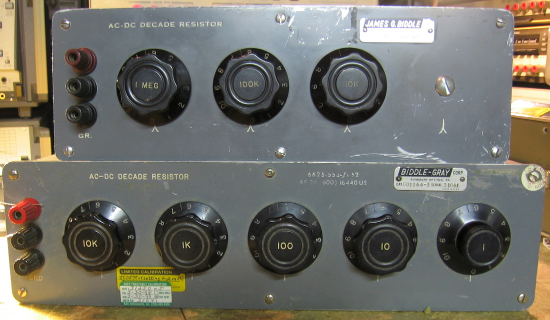
Biddle Gray: Basic decade resistor boxes, 1 ohm to ~111,000 ohms on the lower unit and 10K to ~11.1 Meg on the upper. About 0.035% accuracy as far as I can tell. Built like a tank with precision hand adjusted wire-wound resistors (except on the 1M range). They don't make them like they used to I guess. I actually have no idea when these were made - my guess is around 1960 (if not earlier). These are extremely handy when calibrating DMMs. (---) Grade: A-
The lower unit was fine. The upper unit, purchased about two years later, had one blown 1 Meg resistor. The resistor was marked 0.03% but I replaced it with a 0.05%, 10 ppm/degC temperature coefficient resistor for a couple of bucks. It actually measured 1.0003 Mohms on a calibrated HP 34401A DMM at work, so I guess I was lucky. I can go for the 0.02%, 5 ppm/degC Caddock resistor if I want to spend more than I paid for the whole unit. Maybe someday.
The lower unit was fine. The upper unit, purchased about two years later, had one blown 1 Meg resistor. The resistor was marked 0.03% but I replaced it with a 0.05%, 10 ppm/degC temperature coefficient resistor for a couple of bucks. It actually measured 1.0003 Mohms on a calibrated HP 34401A DMM at work, so I guess I was lucky. I can go for the 0.02%, 5 ppm/degC Caddock resistor if I want to spend more than I paid for the whole unit. Maybe someday.
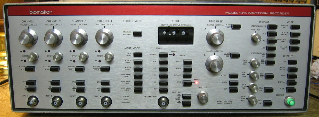
Biomation 1015: Biomation (also known as Gould) produced some specialty equipment decades ago, most notably some of the first logic analyzers. This entry is one of their waveform digitizer/recorders. It basically samples 4 channels at up to 100 kHz with a total storage capacity of 4096 10-bit samples. Once a capture is made, output jacks on the back can be routed to, for instance, a scope for playback. The scope presentation is a bit unsettling at first, especially at low sample rates, because the analog waveform holds the voltage level constant until the next sample point; so the waveforms look like staircases. Looking at the picture, the left third controls the four input levels and has nifty LEDs to tell you whether you are underflowing and/or overflowing the range. The middle third controls the triggering and time base and the right third controls the mode and several types of analog and digital output selections. Built in 1975 with very good build quality and a massive 100,000 uF electrolytic capacitor on the 5V supply. With 74 front panel controls, this piece has the potential for having the all time highest button-to-dollar ratio. But only if the purchase price (not counting shipping) was low. Is $1.00 low enough? I thought so. (OM) Grade: B+
It all seems to work, but I did remove the flickering power-on light bulb, file the crap off the contact, and reinstall. I also discovered that the manual trigger LED would never come on despite the fact that the manual trigger function worked fine. I went through the tedious procedure of removing the front panel and the board behind it and quickly saw the problem. The LED was on a small daughterboard mounted perpendicularly to the main display board. But instead of using an edge connector, Biomation simply drilled a slot through the mother board and stuck the edge of the daughterboard through the slot. Solder was then used to bridge the connections between the two boards. Over time, the stresses cracked all of the solder and the daughterboard was not making contact. I would still like to calibrate the unit, but the cal procedure requires the use of two Biomation support cards which are unobtainable, so I am out of luck.
Postscript: Another few years and another malfunctioning LED. Same bad solder joints on one of the daughterboards as previously described.
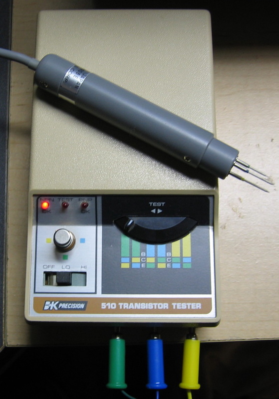
BK Precision 510: Attach the transistor and move the switch at the right until the NPN or PNP LED is lit. No light = bad transistor. This little innocuous piece is probably one of the most useful things I own. It has diagnosed problems countless of times. The best thing about it is that it will do in-circuit tests (as long as shunt resistances are high enough). I also have the accompanying 3-prong probe in case I don't want to use three separate clip leads. (OM) Grade: A-
Postscript: Many years later, picked up a second one of these for $18. It came with a case and three color-coded banana-to-minigrabber leads (to complement my 3-prong probe) which are really all I wanted.
The second 510 unit's eBay photo showed a severely corroded battery holder, so I knew I was going to need one of these. But it isn't a regular 4xAA holder since the 510 uses a split supply (-3V, +3V) with an extra lead coming off the holder to ground. There is no good way to add the ground lead to the place where batteries #2 and #3 meet since they use the kind of steel that is unsolderable. So the simple solution was to get two 2xAA holders and configure them for a split supply. While I was waiting for this second 510 to arrive, I verified the battery holder configuration on my first unit. And in the process of looking, that battery holder's wires crumbled into dust. So I ordered four of the 2xAA holders, enough to fix both units. The first unit was easily fixed, but the new arrival still had problems after I installed the new battery holder. One problem was an improperly soldered IC on the main board and a malfunctioning Off-Lo-Hi slide switch. I think I have both problems fixed now.
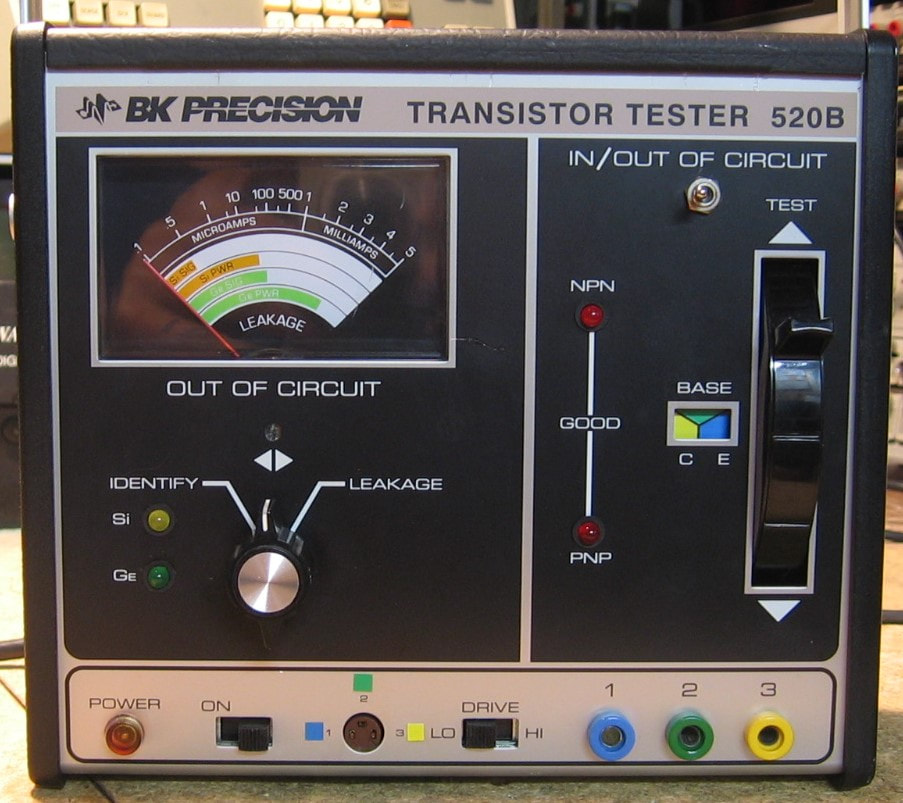
BK Precision 520B: Transistor tester, the upgrade to the BK Precision 510 (described above). The 520B has a couple of differences: 1) it is AC powered so there are no pesky batteries to leak all over the insides; 2) it has a leakage meter; 3) it can identify Ge vs Si transistors; and 4) produces an audible tone when a good transistor is tested. It is also about 10 times the size of the 510. Some would call these 520B features actually disadvantages, particularly the audible tone - it is simply annoying. However, the tone probably has some value if one was using the 3-prong probe (see the 510 entry) and rapidly testing many transistors on a board where you wouldn't have to look up and see the red LED turn on. Of course, one can test transistors in almost all cases with a modern DMM set to diode mode. But I like these self-contained BK Precision testers. The 520B was an OK buy at $20 and arrived in mint condition. (PDF) Grade: B+
Postscript: Playing around with the 520B, I noticed that even on the LO test setting, most bipolar transistors will test OK in two lead configuration switch settings. As explained in the manual, this is due to the small gain seen in the reverse E-C direction in modern transistors. The 510, on the other hand, rarely tests OK in two switch positions on the LO setting. I think this discrepancy is due to the +/-5 volts used in the AC powered 520B versus the +/-3 volts used in the battery powered 510. It's somewhat annoying with the 520B because when two switch settings test OK, there is confusion between which is C and which is E which makes lead identification impossible.
The only thing I needed to do was to calibrate the current meter. However, if you notice, the BK 520B lead identification windows (middle right) shows E B C in terms of three colors (yellow, blue, green). These colors correspond to the colored jacks (lower right) which are also numbered one, two and three. But slide over to the transistor socket (middle bottom) where only the three numbers are shown. So if your memory isn't good, you have to constantly look at the numbers on the socket, then look at the jacks to see the corresponding colors, and then you can "read" the lead identification windows. On the BK Precision 510, they put colored dots next to the transistor socket. Why they didn't do the same on the 520B is beyond me, so I put my own colored dots on. Also, I put a switch (top right) to turn on/off that pesky audible output. That's the way the 520B should have been built in the first place.
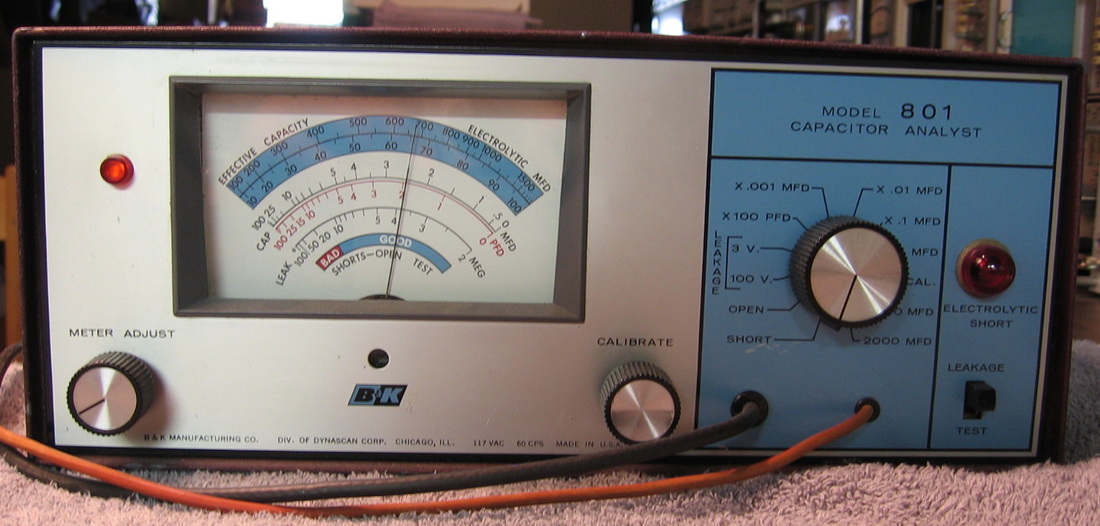
BK Precision 801: Capacitance tester for the 1960's TV repairman. Has an actual vacuum tube inside. Works very well for moderate values of C. I have two things with vacuum tubes - this unit and the GenRad noise generator. Maybe now I need to buy a tube tester? (PDF) Grade: C
This was a simple fix. It just needed a dual pot replaced.
This was a simple fix. It just needed a dual pot replaced.
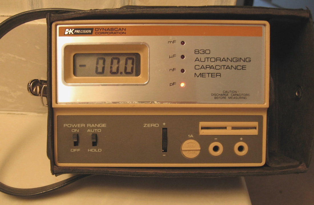
BK Precision 830: Automatic capacitor tester in 10 ranges from 199.9 pF to 199.9 mF full-scale with 0.1% best case accuracy. Not much to do except pop in a capacitor into the clips (or use the banana plugs with clip leads) and read the meter. Takes a few seconds with large capacitors to do the auto-up-ranging and I question the accuracy for small caps < 50 pF (seems to read a bit low). But it is small and portable (runs on four C-cells) and is convenient when I don't feel like using my good LCR meters across the room. Came with case, original manual and original warranty card. I wish to commend BK Precision (Dynascan) because not only is the internal construction first rate, the manual (with schematic and parts list) fully explains the design in very understandable terms. (OM) Grade: A-
There was really nothing to do except Dremel off the corrosion on the battery clips and install a new set of batteries.
Postscript: Went back and did the calibration procedure. The thing was horribly out of adjustment. The readings, especially at low values, are much more accurate now.
There was really nothing to do except Dremel off the corrosion on the battery clips and install a new set of batteries.
Postscript: Went back and did the calibration procedure. The thing was horribly out of adjustment. The readings, especially at low values, are much more accurate now.
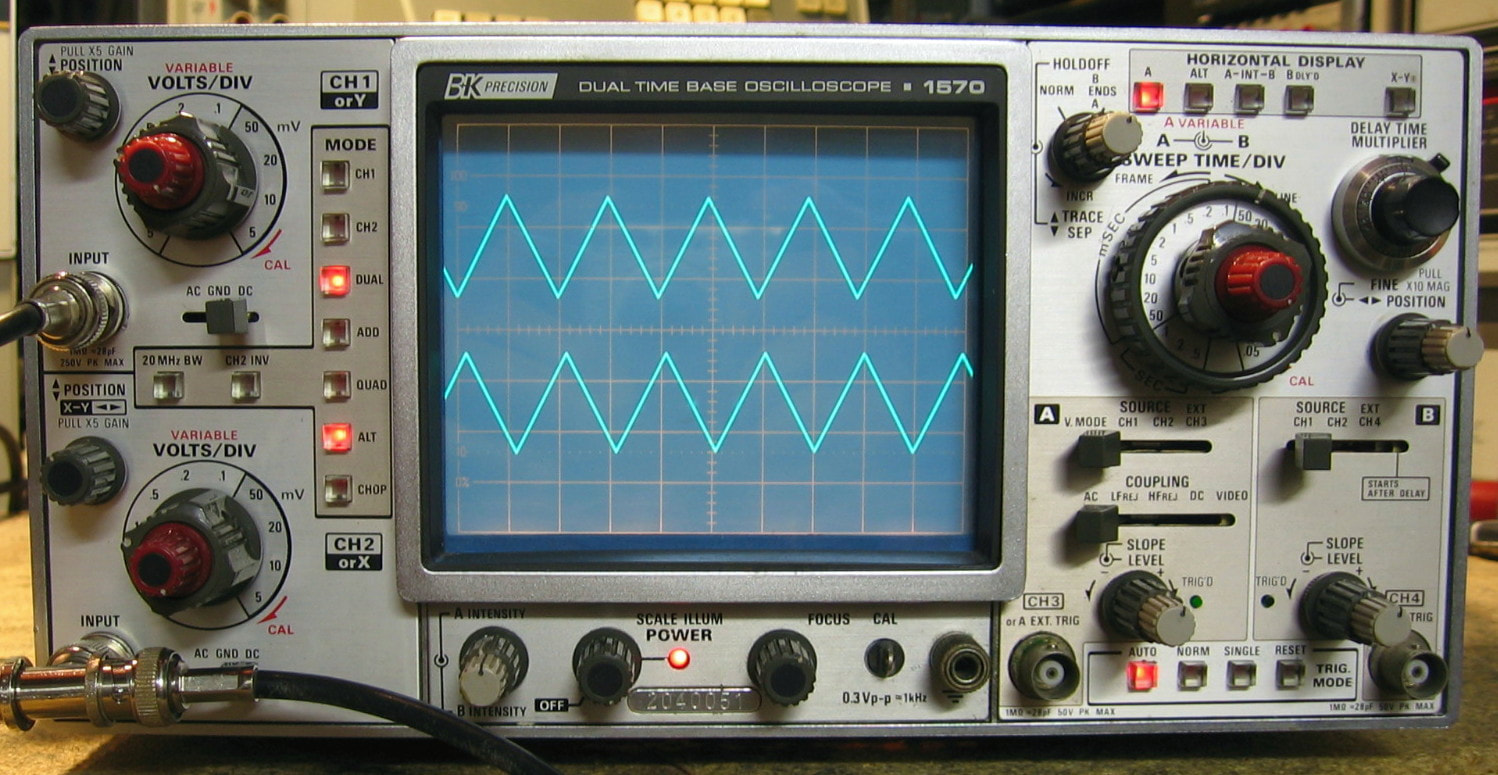
BK Precision 1570: Two (almost four) channel 70 MHz dual timebase oscilloscope. The 1570 is a re-badge of the Kenwood CS-2070 scope. Although the front panel says BK Precision, the boards inside are all marked with Kenwood part numbers. I call this scope "almost four" channels because channels #3 and #4, although usually used for external triggering, can be viewed when the scope is put in "quad" mode. These two channels, however, have a fixed volts/div scale of 0.1 making them sort of useless for general purpose input signals. Otherwise, the scope does what it is supposed to do with minimal fuss. This would be an almost perfect scope if it had automatic peak-to-peak triggering like most of the Tektronix scopes. The design is typical of high end consumer grade electronics (see BK Precision Bonus Rant immediately following) and consists of only two custom designed pre-amp chips. There are a few 7400 and 4000 series logic chips used mainly to service the various front panel selections; the rest of the scope is implemented basically with discrete transistors. A high-end scope manufacturer like HP, Tektronix or Phillips would have designed a few custom triggering and sweep ICs and been done with it. Oh, there are also north of 50 adjustment pots and caps in this beast and there is no cooling fan despite the scope drawing about 65 watts. (PDF) Grade: B
There were several different eBay auctions offering the 1570 at prices less than $75. I chose mine because the listing photo at least showed traces on the screen (I paid $40). When received, the scope was pretty filthy and a lot of it didn't work. The faults were all mechanical, not electrical, and involved a lot of contact cleaner and some touch up soldering. However, there was one big problem. For some idiotic reason, the vertical position adjustments for channel #3 and #4 have their knobs on the side of the cabinet. The pots are on an internal board and the knobs simply come out through two holes cut in the cabinet. There is a warning on the back panel instructing you to remove these two knobs before sliding the cabinet off. The previous owner didn't heed that warning and cracked both pots in half. I managed to remove the pots, put them back together and re-install. A couple of days later, something wasn't working right so I pulled the cabinet off again to take a look. I guess I am the idiot because I yanked the cabinet off without first removing the two knobs. Cracked the pots again and I had to do the repair all over. The calibration went OK as far as I could do it. The timebase board was an earlier version than what is described in the CS-2070 manual and hence none of the adjustments matched. Trial and error has me pretty close, but there is a small error in the timebase that I will have to live with.
Postscript: When I first got the 1570, the channel selection function was not operating properly, but promptly fixed itself. Unfortunately, the fault reared up again and seems to occur only when the unit is cold. There are a bunch of OR gates (74LS32) feeding a J-K flip flop with master set and reset (74LS112), and the reset pin of the 74LS112 (when supposed to be low) was 1.5V - sort of indeterminate for TTL logic. I replaced the 74LS112, but that was not the problem. The 74LS32 output, which drives the 74LS112 through a diode (reverse) was only pulling down to about 0.8V (hence the 1.5V on the 74LS112 was one diode drop higher). But the big clue was when I put my thumb on the 74LS32 and pressed firmly. Down it went from 0.8V to about 0.15V. I removed and resoldered the 74LS32 and all seems OK now - no more changes with my thumb.
Postscript^2: Would really help if I soldered the 74LS112 properly and a wire didn't fall off the channel #3 vertical position pot. NOW everything works properly!
Postscript^3: Well, everything worked for a few weeks. Then same old problem with the channel selection. This time I pulled out the 74LS112 and took a bunch of traces with it. I point-to-point rewired all the missing traces and found a couple of marginal solder joints on a few other adjacent chips. Hopefully this fixes the damn thing once and for all.
BK Precision Bonus Rant: This is more of an observation than a rant. In my opinion, when looking at electronic equipment manufactured before, say, the year 2000, one can put them in one of three categories. The first category is low-grade consumer electronics like what would be found in a cheap AM/FM clock radio. These have the lowest quality boards and components and are clearly designed to be as cheap as possible. The third category is high-end test equipment like what would be found in a typical HP or Tektronix piece. Highest quality everything and clearly designed with less (or no) emphasis on cost. The second, middle category is what I will call high-end consumer grade. If you've ever worked on a ham radio transceiver from Icom, Yaesu or Kenwood, those are good examples. The components tend to be high quality, the boards less so, and almost every function is put on some PC board with the result that there are dozens and dozens of little connectors everywhere because none of the boards plug into any kind of main motherboard. The BK 1570 scope is a prime example of this second category. However, in the case of the 1570, I have never seen ANY piece of electronics with as many add-ons, bodges and revisions. For instance, the vertical preamplifier board must have at least 25 resistors, diodes, capacitors, etc. tacked on to the original board. The horizontal timing board has a little circuit board that was added by hot gluing it on standoffs to the timing board and the underside of the board is a nightmare of tacked-on circuitry. All in all, someone at BK Precision must have spent hours and hours making all the mods.
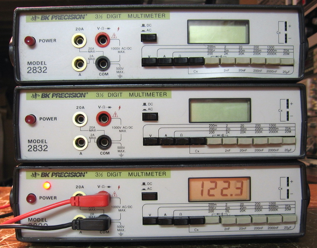
BK Precision 2832: This is a basic 3-1/2 digit multimeter measuring voltage, current, resistance and limited capacitance. Nowadays you can get something similar at Radio Shack for under $20. I thought I was buying one of these, but five actually showed up in various states of disrepair. It is the only thing I have that has a diode tester. And that's the only time I ever use it. Battery powered. (---) Grade: C
Most of the fixes were simple stuff like broken wires. Kept a couple and threw the rest in the garbage.
Most of the fixes were simple stuff like broken wires. Kept a couple and threw the rest in the garbage.
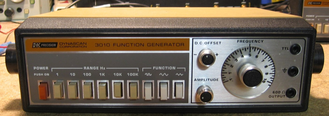
BK Precision 3010: 1 MHz function generator, pretty basic. Suitable for trade schools, the 3010 does sine, square and triangle waveforms, although there are provisions on the back panel for inputting a VCO voltage. The 3010 has a 600 ohm output impedance and will do 10 Vp-p into a 600 ohm load and about 25 Vp-p open circuit. The specs say <1% distortion, but I am getting about 0.5%. However, the spec also says the rise time (at the highest frequency) should be <100 nsec; I'm getting about 170 nsec. Pretty anemic, single-sided PC board (with lots of jumpers). BK Precision, or whoever actually designed and made this thing, definitely was trying to hit a price point. I bought the 3010 for $40 only because the eBay test equipment listings have been sparse lately and I was getting desperate to fix something. The catch was that my $40 got me four of these! However, it wasn't until I went to plug them in that I realized BK used a non-standard AC receptacle. That earns them a full one letter grade deduction. (PDF) Grade: C
Advertised as being bought from a local college in a surplus sale, the seller said he couldn't test it because he did not have a power cord or test leads. Well, I have heard that excuse a million times and thought nothing of it. But when I received the four units, it was clear why the seller did not have a power cord - probably nobody has a power cord. I have no idea why BK used a non-standard AC receptacle. Not even the old-style HP cord is usable. Moreover, the way that the existing receptacle is riveted into a small metal bracket makes it impossible to replace with a standard IEC socket. I'm not sure at this point what I want to do. I could drill a hole in the back and make a captive power cord. Or I could try to drill a square hole for an IEC socket in the back plastic panel. In the meantime, a couple of minigrabbers onto the pins of the AC receptacle will have to do.
When received, none of the four units worked correctly. However, a liberal dose of contact cleaner in the front panel switches and pots rendered all four functional. The 600 ohm output is not to my liking (let alone the excessive rise time), so I converted one unit to 50 ohms (now getting about 60 nsec rise time). I also added a front panel power LED. Finally, I decided to drill a hole in back and run a captive power cord.
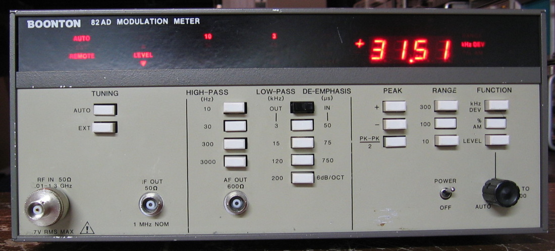
Boonton 82AD: A weak version of the HP 8901A modulation analyzer. Pretty accurate, but running it in the "manual" mode using the level control is wishful thinking. I would put the performance of this unit midway between the HP 8901A and the Marconi TF2304. Nothing special. ($CD) Grade: B+
Someone decided that the unit might like to measure the modulation of a few hundred watt signal. Front end - poof! The input board was actually burnt to a crisp. I removed all the parts, cleaned the board up, added jumpers where the traces had vaporized, and installed new parts. I also had to replace the level potentiometer and repair a short on the GPIB board.
Postscript: See the "Remote" light on the front panel in the picture? I thought I had completely fixed the GPIB board, but the thing sporadically will come up this way (with the front panel locked out). I tested a lot of the chips on the GPIB board, but could find nothing wrong. Then it occurred to me to check the 5V rail - it was 4.5V. So no wonder the GPIB circuitry was flaky. I didn't think at first to check the voltages because the rest of the machine had the correct 5V. But after consulting the schematic, turns out that Boonton ran a dedicated isolated supply for the GPIB board which consists of a bridge rectifier and cap providing 10V unregulated and a 5V regulator on the GPIB board itself. Turns out that the cap was bad and was only supplying about 8V to the regulator through a 5 ohm resistor. The current drawn by the GPIB board then reduced the input voltage to the regulator to about 6V - not enough. A new cap cured all ills.
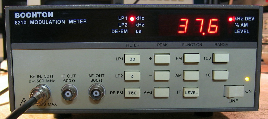
Boonton 8210: A weak version of the Boonton 82AD listed above. Responds to RF from 2 MHz to 1.5 GHz with FM deviations of up to 100 kHz and AM depths to 100%, both in 10 and 100 ranges. Pretty self-explanatory from the picture. The demodulator does its thing and a Z80A uP does its thing. (PDF) Grade: B+
Advertised as display not working, I thought it would be a simple fix. I was wrong, and the culprit seemed to be the Z80A reset circuit on power-up that was not functioning correctly, so the processor would simply hang. Many pointless hours later, I still had not gotten to the bottom of it, even though the reset circuit basically consists of a resistor and a capacitor. It might have been due to the leaking AAA batteries inside that covered part of the processor board in green crud. Anyway, I'm not inclined to pursue it further. I simply lifted the reset pin of the Z80A out of the socket and attached a small pushbutton switch on the back panel that grounds the line (while being held high by a pull-up resistor). Turn it on, press the button for a second and let go. Works fine.
Postscript: To show you all what kind of fool am I, I looked at a later version of the service manual and step 2 of the troubleshooting chart is to check the memory back-up batteries. I initially thought that the absence of batteries would simply cause the calibration constants to be lost, but the unit goes through self-cal for 30 seconds upon start-up anyway. Not so fast. The schematic shows the batteries running through a DS1210 memory controller/battery back-up chip that has the nasty habit of screwing around with the RAM chip enable line if it doesn't like what it sees. Bottom line: two new AAA batteries and the thing starts right up, without any extras like my reset switch, and once the cal was completed, subsequent power-ons omit the start-up cal procedure I've seen this kind of behavior before - see the Racal 5002 below - but what confused me with the Boonton 8210 was that the thing mostly did work with my reset switch. I guess there is some checking by the uP at startup and I was able to get past that somehow.
Postscript^2: Replaced the two AAA batteries which had leaked pretty badly in their plastic enclosure (but surprisingly measured OK) and the front panel power LED (which was very dim).
C : C&C, Chinese No-Name, Circuit Specialists, Clarke-Hess, Cushman
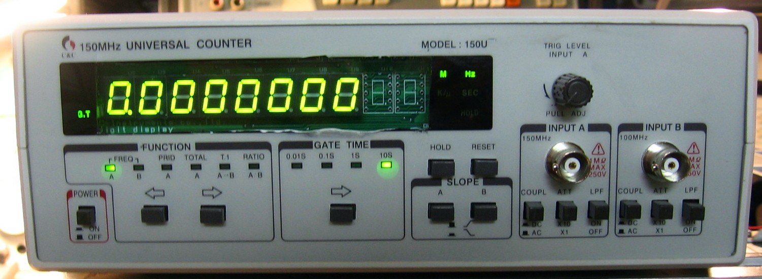
C&C 150U: 150 MHz frequency counter. This is a basic, no frills two-channel counter, as vanilla as it gets. Will do frequency, period and interval or ratio between channels. Input selections include AC/DC coupling, 10:1 attenuation and a 150 kHz low-pass filter. The gate time is selectable and controls the number of digits displayed (maximum of 8). The counter is designed around a custom ASIC and it is clear that C&C had one set of firmware for multiple models because pressing the function buttons leaves a "no-op" condition between Freq B and Period A where there must have been a "C" channel function in another model. Being a 7-digit per second counter, it is a good two or three orders of magnitude worse than your "normal" counter. Designed (and perhaps manufactured) in Korea, the build quality is surprisingly good. That is, until you try and fix it - then you get the real surprise (see the repair notes below). (PDF) Grade: C-
Advertised as not powering up, I couldn't really resist at $19. The unit powered up just fine once you set the internal/external oscillator switch on the back panel correctly (when set to external, the unit actually does power up - it just looks like it didn't since the processor has no clock and the front panel is dead). There is a trigger level control on the front panel which was doing nothing. When I traced the circuit, the pot was wired incorrectly, so I switched two wires and brought the control back to life. But on the "B" channel, things were really hosed. The low-pass filter didn't work right, nor did the AC/DC coupling switch. Again, I traced the circuit and much to my surprise discovered that the front panel labels were incorrect! The three switches for the "A" channel and the three switches for the "B" channel are marked (from left to right), Coupling, Attenuation, Filter. But the "B" channel was actually wired as Filter, Attenuation, Coupling. I went back and looked at a bunch of eBay pictures of this model up for sale and saw several that were marked on both channels Coupling, Attenuation, Filter, and several that were marked Filter, Attenuation, Coupling. Nowhere did I see Coupling, Attenuation, Filter on one channel and Filter, Attenuation, Coupling on another. Perhaps there was a board revision and my unit's board was repaired with the wrong rev. Remains a mystery to me. Finally, as the picture shows, the display window looks terrible. That's because my units plastic window was nearly opaque and when I went to clean it with alcohol, the window turned into a gooey mess. So I hacked it out and put a piece of acrylic in. I did a terrible job, but then again, when will I ever actually use this piece of junk?
Advertised as not powering up, I couldn't really resist at $19. The unit powered up just fine once you set the internal/external oscillator switch on the back panel correctly (when set to external, the unit actually does power up - it just looks like it didn't since the processor has no clock and the front panel is dead). There is a trigger level control on the front panel which was doing nothing. When I traced the circuit, the pot was wired incorrectly, so I switched two wires and brought the control back to life. But on the "B" channel, things were really hosed. The low-pass filter didn't work right, nor did the AC/DC coupling switch. Again, I traced the circuit and much to my surprise discovered that the front panel labels were incorrect! The three switches for the "A" channel and the three switches for the "B" channel are marked (from left to right), Coupling, Attenuation, Filter. But the "B" channel was actually wired as Filter, Attenuation, Coupling. I went back and looked at a bunch of eBay pictures of this model up for sale and saw several that were marked on both channels Coupling, Attenuation, Filter, and several that were marked Filter, Attenuation, Coupling. Nowhere did I see Coupling, Attenuation, Filter on one channel and Filter, Attenuation, Coupling on another. Perhaps there was a board revision and my unit's board was repaired with the wrong rev. Remains a mystery to me. Finally, as the picture shows, the display window looks terrible. That's because my units plastic window was nearly opaque and when I went to clean it with alcohol, the window turned into a gooey mess. So I hacked it out and put a piece of acrylic in. I did a terrible job, but then again, when will I ever actually use this piece of junk?
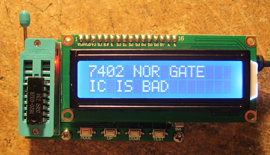
Chinese No-name TES200: This is an integrated circuit tester. I have no idea who the manufacturer is but it was less than $40 shipped to my door from China. This thing tests 7400 TTL and 4000 CMOS series chips, several hundred of the most popular numbers; just what I need for 1970's and 1980's vintage repairs (but pretty worthless for modern equipment). The operation couldn't be simpler: Use the mode button to switch between TTL and CMOS, then use the up/down buttons to select the chip number, insert the chip into the ZIF socket (pin 1 up) and press the test button. If it is a multi-gate chip like a quad NOR, the display will strobe out Gate 1 OK, Gate 2 OK, etc., until the end when a good/bad conclusion is presented. Obviously there is no connection to a computer and no hope of adding new chip data. In fact, the processor on the board has been sanded down to remove the markings. I guess the Chinese are afraid someone even cheaper than them will mass produce the thing. On the whole, however, very nifty and useful. (PDF) Grade: A-
Postscript: Picked up another no-name Chinese IC tester for twenty bucks (picture not shown). This one is being sold as a "Multi-Function IC LED Optocoupler LM399 DIP Chip Tester." Operating off of a single AAA-cell, one inserts a 7400 or 4000 IC, presses the button, and a single alphanumeric LED strobes out the chip ID if good. It also can light up LEDs of all kinds and test about a dozen non-logic chips. Seems to work as advertised, but sometimes can give you the wrong ID (namely any other IC that has the same functional inputs and outputs). (PDF) Grade: A-
Postscript: Picked up another no-name Chinese IC tester for twenty bucks (picture not shown). This one is being sold as a "Multi-Function IC LED Optocoupler LM399 DIP Chip Tester." Operating off of a single AAA-cell, one inserts a 7400 or 4000 IC, presses the button, and a single alphanumeric LED strobes out the chip ID if good. It also can light up LEDs of all kinds and test about a dozen non-logic chips. Seems to work as advertised, but sometimes can give you the wrong ID (namely any other IC that has the same functional inputs and outputs). (PDF) Grade: A-
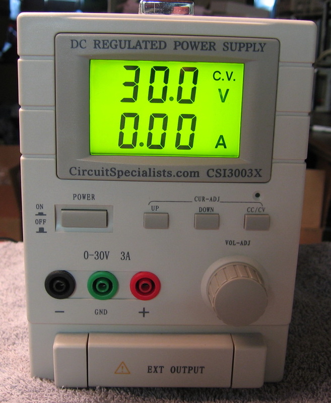
Circuit Specialists CSI-3003X: 30V, 3A P/S. Made in Taiwan, but very impressive build quality inside. One of the few pieces I bought new (early in my career, before I knew any better). One can never have too many power supplies. I needed four of them when I was fixing the Wandel & Goltermann SPM-19! (OM) Grade: B+
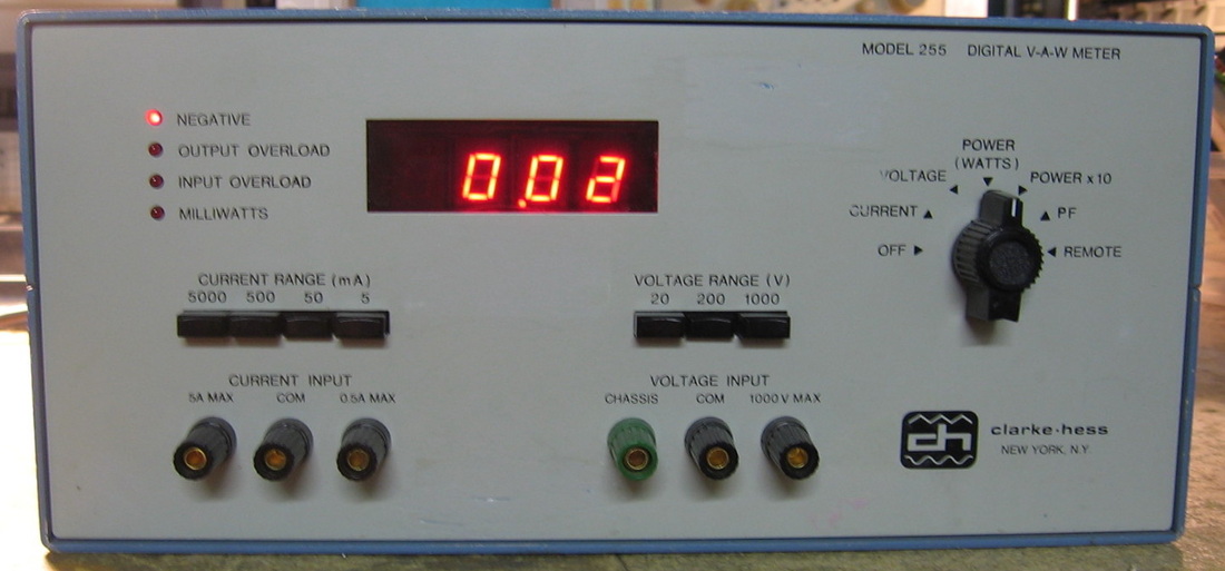
Clarke Hess 255: Digital Power Meter. Quoting from the brochure, "The Model 255 digital V-A-W meter provides true RMS measurements of voltage, current and power, essentially independent of the waveshape, and the power factor from DC up to frequencies of hundreds of kilohertz." Now, I have plenty of DVMs which will measure voltage and current, and my Sencore isolation transformer also measures AC line wattage. But this is the only piece that will tell me the power factor. Which turns out to be about 0.6 for just about every piece of test equipment I measured. One needs only to put the (return side) of the load in series with the two I banana plugs and the total load across the two V plugs, select the V and I ranges on the front panel, and sit back and enjoy the digital readout. My unit came with the digital I/O board which does me no good. It especially does me no good because it sits above the main board and blocks all the adjustment pots. This is my first Clarke-Hess piece and I am impressed with the build quality which is only just slightly below HP-quality. Finally, the brochure goes on to say, the meter is "easy to use, hard to damage, easy to service and easy to maintain." Well, we'll see... (PDF) Grade: A-
Advertised by the seller as powers up, no display. When received, the LEDs did flash for an instant when turned on, but that's about it. Four of the five power supply voltages were zero, so that's not good. The culprit was a 1000 uF electrolytic filter cap which read 0.2 ohms. Funny that with the shorted cap, the thing drew 40 watts from the AC line. I would have thought it would have popped the main fuse. Oh well, two parallel 470 uFs from the junkbox fixed that problem and the unit works fine and only draws the 10 watts it should.
Advertised by the seller as powers up, no display. When received, the LEDs did flash for an instant when turned on, but that's about it. Four of the five power supply voltages were zero, so that's not good. The culprit was a 1000 uF electrolytic filter cap which read 0.2 ohms. Funny that with the shorted cap, the thing drew 40 watts from the AC line. I would have thought it would have popped the main fuse. Oh well, two parallel 470 uFs from the junkbox fixed that problem and the unit works fine and only draws the 10 watts it should.
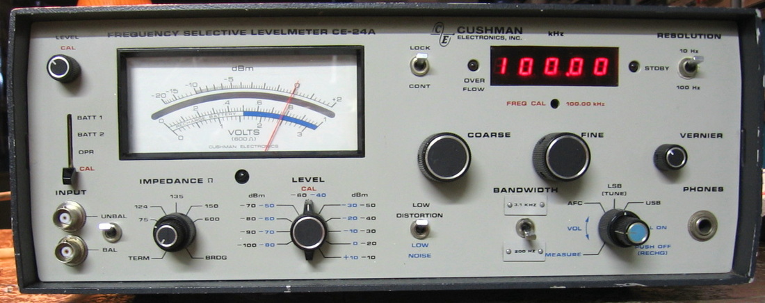
Cushman CE-24A: Selective Level Meter good to about 5 MHz, -100 dBm to +10 dBm. Has 3100 and 200 Hz filters. I can compare this unit to the HP 3586B selective receiver and the Wandel & Goltermann SPM-19 selective receiver. Of course, the CE-24A doesn't have the frequency range of the others, but it handles itself admirably. Cushman has nothing to be ashamed of. ($CD) Grade: B+
This had a faulty 1 uF tantalum in the 3.1 kHz amplifier board that took a long time to find. The overflow LED on the front panel was also open. Those pesky WECO jacks were replaced by BNC jacks.
Postscript: Years later, the AFC stopped functioning. This was found to be a faulty MV104 varactor in the AFC tuning loop. It was replaced with a similar MV2109 varactor.
D : Datron, Di-Bar, Dytronics
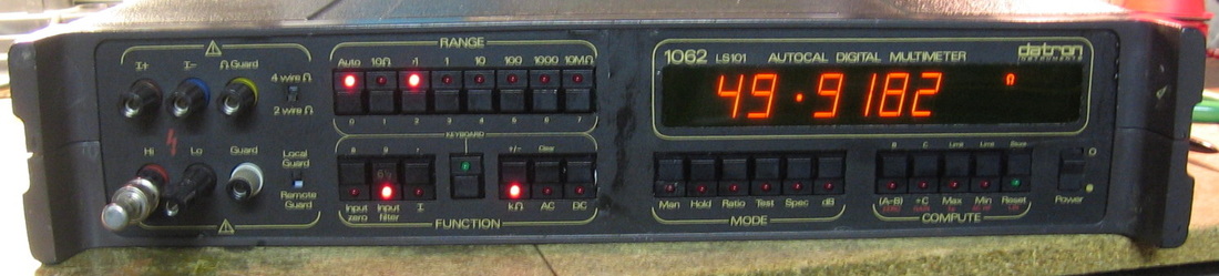
Datron 1062: 6-1/2 Digit DMM. The British answer to the HP 3455/6A or Fluke 8502A. My unit does DCV, ohms and has the Option 12 high performance AC volt board. I've now tried the Datron 1062, the Solartron 7065 and Guildline 9577, all of which advertise and would have you believe that they are better than the HP DMMs. Simply not true, although the Datron 1062 is certainly the best of these off-brands. While it seems adequately accurate, the reading rate is kind of slow (at 6-1/2 digits) and the delay when switching functions is too large. But, it's growing on me as I use it. (PDF) Grade: A-
Postscript: After using the 1062 for a while, I'm a little more impressed. My initial complaint about the slow switching between functions was mitigated a bit after I realized that the HP 3457A (which should be about the best DMM I have) was even worse. The large orange display on the 1062 is very nice - no complaints there. In comparison with the HP 3456A and Fluke 8502A, I have noticed that the Datron tends to drift a bit more during a two-hour warmup. All in all, I wouldn't hesitate to recommend the 1062 if the price was reasonable (<$100). But beware that if the multi-digit display gets toasted, a replacement is unobtainable.
When received, this unit was unresponsive to any front panel inputs. And that's because the switch on the back had been set to use the rear panel inputs! But even after that, there are two relays that need to remain closed at all times when using the front panel jacks; these relays were marginal. So I basically rewired the thing to remove the back panel jack option and thus bypass the faulty relays. I also removed the calibration enable key switch (there was no key) and replaced it with a toggle switch. The front panel guard terminal was snapped off and replaced with a junkbox one (that doesn't match). The calibration also took a few tries since the linearity of the device was difficult to get right. Also, Datron has you, for instance, give it a 1V calibrated source, then punch the cal button that writes a cal constant into memory so that the display will read 1V. You repeat this procedure for 10V, 100V, etc. And then they have the nerve to tell you to check the performance by testing the device at 1V, 10V, 100V, etc. That's ridiculous - of course the thing will be accurate at those points, because you just told it the constants needed to be accurate at those points. But what happens at an intermediate point, say 5V? Anyway, all seems relatively OK now, but there are still a few more relays inside and all the ICs are socketed. And a couple of times, the thing wouldn't boot, random characters were flashed on the screen, and a quick 5V P/S measurement proved faulty. I suspect a tantalum somewhere had a brief short before popping open. Also, it lost the cal constant on the 10 VDC range out of the blue once. So stay tuned for further maintenance...
Postscript: Well, the Datron 1062 has been acting up a bit after it is sufficiently warmed up. The display suddenly flashes "Error OL" the unit becomes partially unresponsive and the transformer hums. I suspected the LM309K 5V regulator rather than my earlier guess at a tantalum that was marginal. Unfortunately, the regulator is pretty well hidden under a mass of wires and other pass transistors in the P/S. But I did see one wire coming off the lug holding the TO-3 can (the regulator ground lead) that was all rusted. So I decided to dissect. An hour later, I got everything apart only to observe the following: 1) the ground lead was indeed all corroded, 2) the in and out connections to the regulator were completely burnt, 3) the in and out leads basically fell off into my hand when I touched them, 4) the anodized aluminum heat sink was all scarred and corroded with white crust underneath the two wires connected to the part and 5) the adjacent pass transistor for the display had a broken plastic screw/nut that held it to the heat sink, so that transistor was only being marginally cooled. I replaced the LM309K with a junkbox part, rewired everything and remounted the other pass transistor. I then ran it with no incident for 4 hours. Problem hopefully solved.
Postscript^2: One day, after an hour of operation, the thing suddenly locked up with the "Error OL" message on the screen. A quick check of the power supplies showed the +15V supply near zero. The fault was isolated to a bad bridge rectifier feeding the +/-15V split supplies. A dead giveaway was the 60 Hz ripple also seen on the two supplies. All of these repair notes should convince you that the P/S is pretty much crap in these units. It's not that it is electrically incorrect, it's simply that they jammed it in the rear section where it is inadequately ventilated (in my humble opinion).
Postscript^3: On the advice of some repair posts on eevBlog, I replaced the six blue Philips electrolytic caps on the main analog PCB. Four of the six had lost >50% of their capacitance and many had ESRs greater than 20 ohms. Call it preventative maintenance.
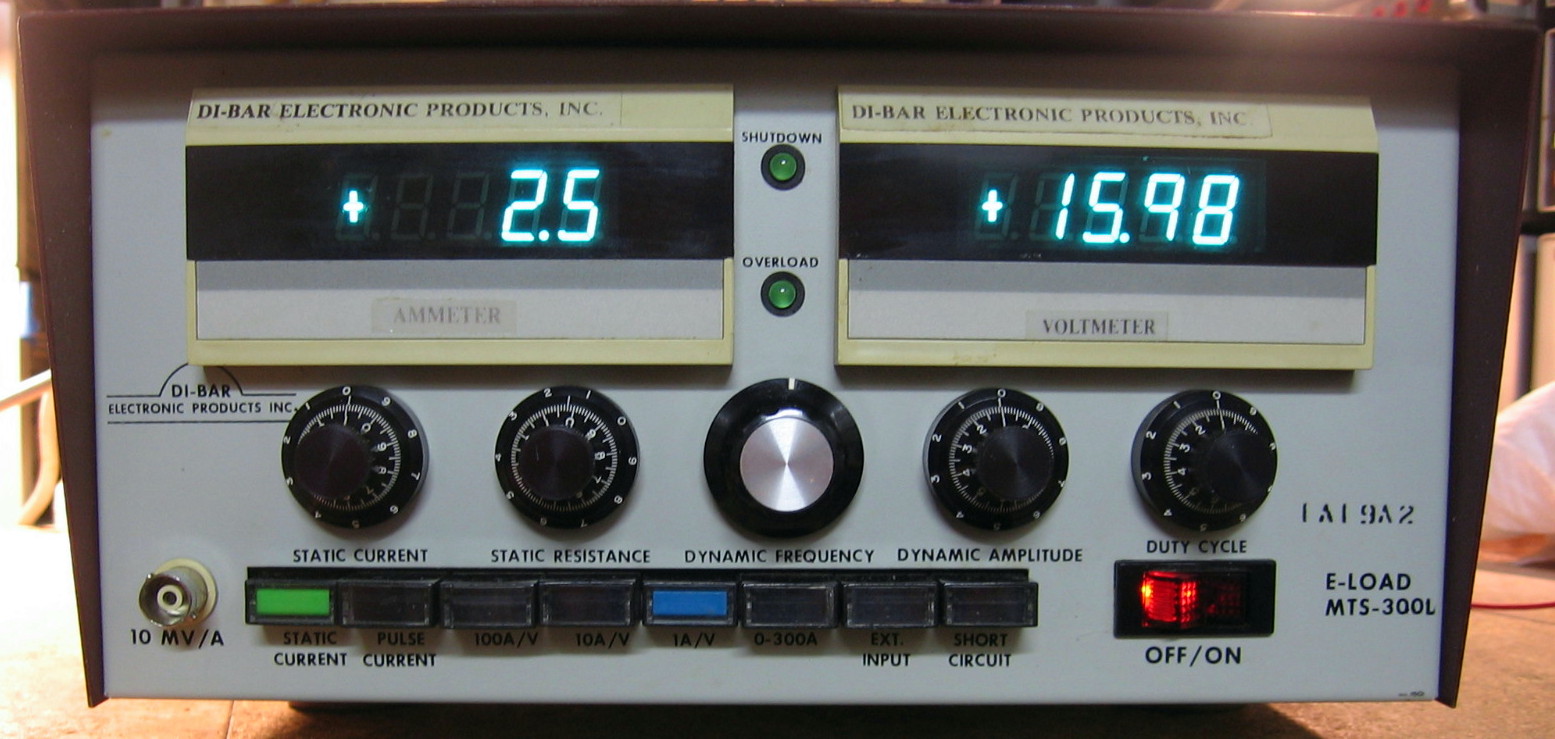
Di-Bar MTS-300L: Dynamic electronic load. I can find absolutely no information about Di-Bar or this particular model. But, judging from the 50V electrolytic capacitor across the output, I would venture a guess that this piece is limited to 50 volts. And because one of the front panel buttons is marked 0-300A, I would also speculate that it will handle 300 amps (actually, probably a bit less given the 0.5 ohm emitter ballast resistors). The total power limit is unknown, but given the fact that this beast has 42 2N5886 power transistors, I would estimate that it is in the 1500 watt range. Architecturally, this piece is very similar to the Power-Mate load (see that entry below). The buttonology is similar in that it will do constant current or constant resistance, and also has both static and dynamic (pulse) loading. I like this unit better than the Power-Mate because of the dual metering and 10-turn pots, and it seems to do just what a load should. The build quality is a bit bizarre, however. The load block looks very well engineered. The two digital displays were clearly bought from a third party. The control board uses a puzzling mix of DIP ICs, metal can op-amps and discrete transistors and is filled with bodges. (---) Grade: B+
I picked this unit up (condition unknown) for $50. I figured I needed a challenge given that no manual was available. But the faults were readily apparent. First up, there was a dead short across the input terminals. Normally this would mean that one of the power transistors was shorted. But in this case, the transistors were fine and the fault was a shorted SCR. Second, the front panel pushbuttons were pushed back into the case and this was because the main circuit board had sheared off its plastic mounting standoffs and was floating inside the chassis. Finally, the big relay, used to short the input, had cracked in half and was sitting on the bottom of the unit. So this piece, at some time during its storied life, really took a massive shock. All three of these faults were easily remedied, although epoxying the relay housing back together was a bit dicey.
Postscript: One day, this unit acted up whereby the current meter was fine, but the voltage meter was reading about 2x high. Both these meters are old Digitec panel meters and the schematic is nowhere to be found. So I pulled them both out, took the covers off, and hooked them up in parallel to the incoming voltage line. By comparing voltages on the various IC pins, there was a discrepancy on the AD650 voltage-to-frequency converter. I swapped the two ICs and the fault followed suitably. Mouser wanted $30 for the AD650, but I took a chance and found five for $20 on eBay. Normally I don't like to buy ICs on eBay; the ones from China are almost always counterfeit and even the ones from a USA seller are risky because he might have obtained them from China! But the label on the ICs looked fine and it turned out the ICs were fine too.
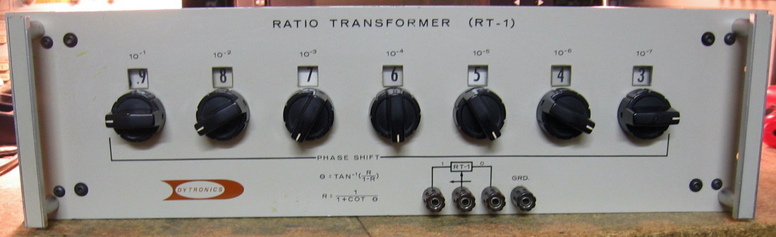
Dytronics RT-1: AC Ratio Transformer. The RT-1 is the AC equivalent of a DC divider (for example, my ESI RV622A), Gertsch was the number one manufacturer of these things years ago (before they got bought, and bought again, and bought again). Unfortunately, I can find absolutely nothing on the Dytronics versions. But if it is anything like most of the Gertsch models, it operates best between 50 and 10,000 Hz (400 Hz is the optimum), and will take AC input voltages up to 0.35*freq(Hz) or 350V, whichever is smaller. My unit has seven decades which is pretty amazing if you think about it. In fact, it is so amazing that I have no AC voltmeter that really can see all of the digits at once. I don't know the accuracy and linearity specs, but my guess is that they are in the 10 ppm range (if not slightly better). A particularly nice feature of this unit, unlike the DC dividers, is that you can set the output slightly higher than the input (about x1.1). You can, of course, also run it in reverse at your own risk (my unit is unfused on both sides). Quality 1960s-era construction using double and triple redundant switches and a set of transformers in about 1/2-gallon of potting compound. Tegam still makes a very similar unit (DT72B) for $15,000, so the $45 I spent for mine was a good buy! (---) Grade: A
E : Electronic Development Corp, EH Research, EIP, E-Jin, ESI, ETS, Exact, EZ Digital

Electronic Development Corp 501: DC calibrator a la the Fluke 343A. Voltages are set by flicking the various 2^N divisor switches from a starting value of 10.24V (or 102.4 mV). Well isn't this a joy to use. If you want to do 3.14159 volts, you have to figure out the binary representation and then flick the corresponding switches. Real intuitive, isn't it? Also, there are 20 bits and if you think the output has such low noise that you can actually see the lower order bits, then I'd like to sell you this unit for $1,000. (OM) Grade: B-
The usual blown power supply. Couldn't get the Raytheon dual tracking regulator anymore, so I rewired the P/S board and installed 7815 and 7915 regulators. Also replaced the blown up electrolytics.
The usual blown power supply. Couldn't get the Raytheon dual tracking regulator anymore, so I rewired the P/S board and installed 7815 and 7915 regulators. Also replaced the blown up electrolytics.
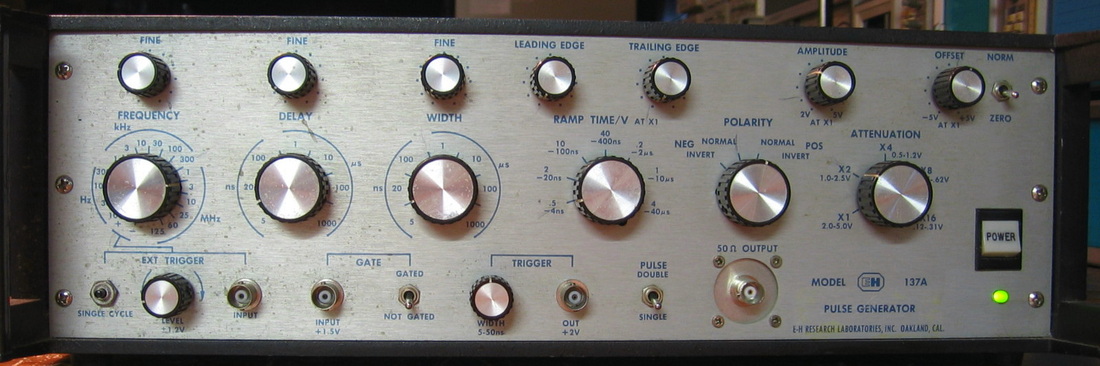
EH Research 137A: Quite capable pulse generator to > 125 MHz. What is most surprising is that this unit beats just about every other pulse generator of the era, yet has very few parts inside comparatively. How did they do it? When I need fast pulse rates, this is the unit I turn to. Has a 120VAC fan that sounds like a jet engine when it is running. (---) Grade: A-
Didn't have the schematic, but the problem was pretty easy: replace the blown power supply pass transistor. I also replaced the GenRad connector on the front panel with a BNC connector and added a power-on LED.
Didn't have the schematic, but the problem was pretty easy: replace the blown power supply pass transistor. I also replaced the GenRad connector on the front panel with a BNC connector and added a power-on LED.
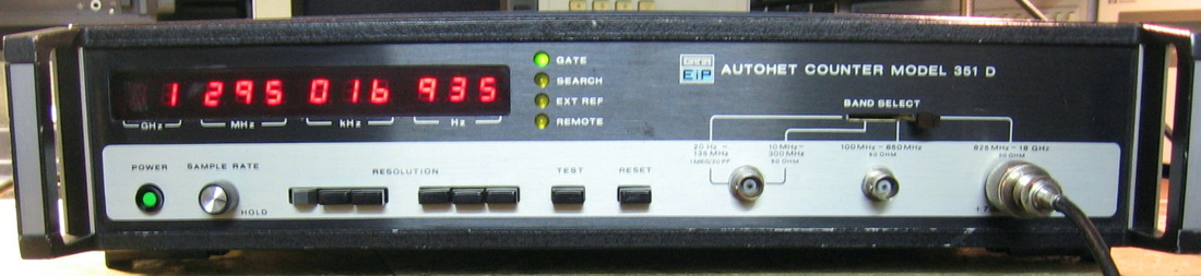
EIP 351D: Microwave counter to 18 GHz. EIP eventually became Phase Matrix who still sells similar counters today. The counter has three bands. The first band goes to 300 MHz (with both a 1 Mohm and 50 ohm selection) using a direct counter with 1 Hz resolution. The second band covers 100 MHz to 850 MHz using a pre-scaler to feed the basic Band I counter. The third band goes from 825 MHz to 18 GHz and is where all the microwave magic happens. The idea is to heterodyne the GHz signal down to <200 MHz where it can be fed into the Band I counter. HP did something similar with their 5254B plug-in for the 5345 counter. But unlike HP's manually tuned cavity oscillator, the EIP 351D tunes automatically and uses a YIG filter. Basically, a 200 MHz oscillator drives a non-linear device that produces 200 MHz pulses rich in harmonics. The YIG filter is then swept along in 200 MHz increments up to 18 GHz. Eventually, one of these filtered harmonics is within 200 MHz of the input signal and stops the YIG sweep. A mixer is used to get the baseband signal from the input and YIG. It takes about 200 msec worst case to do the initial sweep and the counter is rated to about -30 dBm input sensitivity. The 351D has a unique front panel arrangement where a series of six buttons select the resolution you want to see. This is not a reciprocal counter like HP often manufactured, so a 1 Hz gate time produces 1 Hz resolution and that's it. But 1 Hz resolution at 18 GHz is good enough for me. ($CD) Grade: A-
Offered on eBay for $60 + shipping, the seller claimed that Band III did not function. And he was right, the search LED was permanently on meaning that the YIG had not locked to the input. Moreover, the unit was advertised has having Option 003, an OCXO, and the sticker on the back panel attested to that. But when I opened it up, all I found was the stock TCXO. Moreover, there was no indication at all that the OCXO, which requires a separate transformer and P/S board, had ever been there. Somewhat disappointing. Anyway, back to the repair which eventually showed that the YIG was being improperly tuned. This was traced to a Zener diode that provides a 3.1 V reference. To make a long story short, the 3.1 V reference was more like 2 V which had the effect of dragging down a bunch of cascaded TTL decade counters rendering the YIG tuning dysfunctional. A new Zener fixed the problem (on the other hand, when I tested the pulled Zener with 10 ma of current, it seemed to be OK, so maybe it was just a bad joint or lead). A quick scope check showed that the YIG was now happily producing 200, 400, 600, ... MHz pulses every 1 msec (or at the first few, since I would need an 18 GHz scope to see them all in the time domain). Yet an input signal to the counter produced nothing on the display, nor did the YIG sweep ever stop. The front panel N-jack goes to a variable attenuator and then to the mixer. The attenuator checked OK, but when I pulled the mixer and applied two signals to it, I got nothing out. I dissected the mixer only to find a small pile of black dust inside where a component used to be. At that point, I figured the whole piece was destined for the "It's Dead, Jim" pile. But as luck would have it - and I mean a whole lot of luck - I managed to find the exact part on eBay from Israel for $25 shipped. Installed the new mixer and the counter now works as it should. I brought the counter into work where I have access to a signal generator that goes to 18 GHz and the EIP 351D has no problems at all.
Offered on eBay for $60 + shipping, the seller claimed that Band III did not function. And he was right, the search LED was permanently on meaning that the YIG had not locked to the input. Moreover, the unit was advertised has having Option 003, an OCXO, and the sticker on the back panel attested to that. But when I opened it up, all I found was the stock TCXO. Moreover, there was no indication at all that the OCXO, which requires a separate transformer and P/S board, had ever been there. Somewhat disappointing. Anyway, back to the repair which eventually showed that the YIG was being improperly tuned. This was traced to a Zener diode that provides a 3.1 V reference. To make a long story short, the 3.1 V reference was more like 2 V which had the effect of dragging down a bunch of cascaded TTL decade counters rendering the YIG tuning dysfunctional. A new Zener fixed the problem (on the other hand, when I tested the pulled Zener with 10 ma of current, it seemed to be OK, so maybe it was just a bad joint or lead). A quick scope check showed that the YIG was now happily producing 200, 400, 600, ... MHz pulses every 1 msec (or at the first few, since I would need an 18 GHz scope to see them all in the time domain). Yet an input signal to the counter produced nothing on the display, nor did the YIG sweep ever stop. The front panel N-jack goes to a variable attenuator and then to the mixer. The attenuator checked OK, but when I pulled the mixer and applied two signals to it, I got nothing out. I dissected the mixer only to find a small pile of black dust inside where a component used to be. At that point, I figured the whole piece was destined for the "It's Dead, Jim" pile. But as luck would have it - and I mean a whole lot of luck - I managed to find the exact part on eBay from Israel for $25 shipped. Installed the new mixer and the counter now works as it should. I brought the counter into work where I have access to a signal generator that goes to 18 GHz and the EIP 351D has no problems at all.
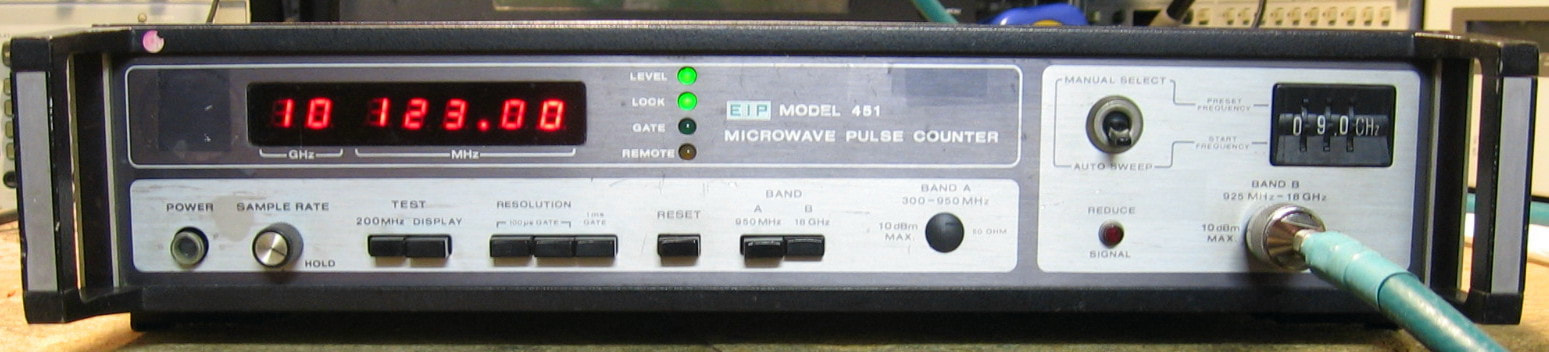
EIP 451: Microwave Pulse Counter. Take a microwave CW signal generator and hook it up to a microwave counter. No problem. Now turn on pulse modulation in the signal generator and look at the counter. Big problem. The counter will just sit there and laugh at you with no readings. The EIP 451 is designed to count pulsed microwave signals (and obviously will also count CW signals). The basic frequency range is 950 MHz to 18 GHz, although there is an option to add a 300 MHz to 950 MHz low band (mine doesn't have this option), and the basic sensitivity is -10 dBm. The 451 will count pulsed signals of basically any pulse repetition rate as long as the pulse width is at least 100 nsec. It does this by opening/closing gates coupled with a long coaxial delay line. The maximum gate time is 1 msec so the 451 does not have the frequency resolution that my other EIP counters have. But that's OK since if you are trying to measure a 10 GHz pulsed signal to a frequency resolution of, say, 1 Hz, you have bigger problems! (PDF) Grade: A-
Advertised as powers up, fans runs, lights blink, but the numeric display flashes briefly and then goes dark. Now the fact that the panel LEDs light up means the 5V supply is working. Normally, the standard alphanumeric LEDs also run on 5V, so why would they be unlit? A brief glance at the schematic shows that the current for the alphanumeric LEDs is controlled by the 12V supply. So my intuition was that the 12V supply was bad, probably caused by a shorted tantalum capacitor (as were numerous tantalums in my closely related EIP 578 counter). So I decided to buy this piece for $40. When received, an ohmmeter showed about 0.1 ohms on the 12V line and about 7 ohms on the -12V line; the +5V and -5.2V lines looked good. So the drill is to leave the ohmmeter hooked up and start pulling boards until the short goes away. This time, both tantalums causing the short and near-short on the 12V and -12V were confined to the A202 board. Once these two were replaced, the 451 seemed to work fine. Well, almost fine. The "g" segment of one of the alphanumeric LEDs would not light. When I pulled the LED out (luckily it was socketed), the pin going to that segment stayed in the IC socket. So it must have severed years ago and wasn't making contact. I extracted the piece and soldered it back to the LED. Works fine now. I've ordered replacement tantalums for all the caps, since if two shorted, more shorts are likely. When I get them, in they will go.
Postscript: Replaced 58 10 uF and 33 uF tantalums. I left a few tantalums that were 1 uF or less because they generally were not hung directly off of one of the power rails (and I didn't have any in stock anyway). Only the two tantalums that I had originally found shorted were bad; the remaining 56 tested OK. But I'm sure the two bad ones tested OK right before they shorted too!
Postscript^2: Turned this on one day and after about one minute heard a big pop (the piece continued to work fine). One of my 10 uF replacement tantalums on the clock board blew half of its top off. No odor, no burn marks, no mess, just blown apart. Moreover it blew open circuit which is why it didn't drag the -12V rail down and the piece still worked.
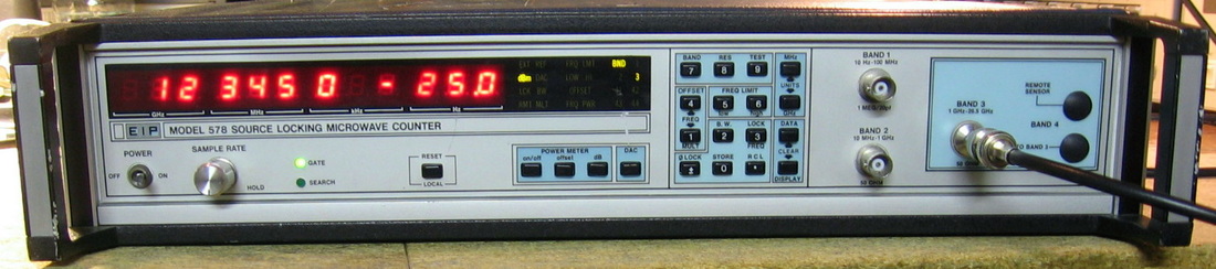
EIP 578: Source-locking microwave counter to 26.5 GHz. First of all, EIP made a bunch of counters all of which were basic variants of their ubiquitous 545 model. A higher last digit in the model number indicates a higher frequency range. For instance, they also made a less capable 575 model. EIP is now Phase Matrix and they still sell the 575B and 578B. I don't know what the "B" model improvements were, but my guess is they beefed up the uP circuitry a bit. But beyond the 26.5 GHz range, the 575/8 models had an extra feature called "source-locking." A jack on the back panel is used to drive any kind of electronic frequency control of your favorite oscillator. Just punch the frequency of the oscillator into the 578, hook up a sample of the oscillator output to the counter input, and the 578 will adjust the oscillator (if possible) to the selected frequency. All this would be good and well if the timebase of the 578 was more stable than the target oscillator. But alas, my unit only has a TCXO. I suppose I could slave an OCXO to the counter's external timebase input if I wanted to then source-lock my target. I can live with the fact that my unit doesn't have Option 01 - the OCXO. However, I was pleasantly surprised upon receipt to see that it has Option 02 - the power meter. The picture shows a 12.345 GHz signal at -25 dBm as displayed on the counter. Note that when the power meter is enabled, the counter truncates the number of displayed frequency digits. Normally, the counter shows 12 digits. On the 578, things are done in three bands with three separate input jacks. At first I found this annoying, but I actually like it since I can have three signal generators feeding the unit at once and quickly scroll through the signals without having to swap cables. Finally, EIP changed the microwave architecture from that of the EIP351D listed above. In the 351D, the input signal goes right to a mixer - hence the high likelihood of a burned-up mixer (like mine was). The 578 runs the input through a YIG filter that is pretty much immune to any amount of power you can throw at it. Another nice feature due to the way EIP architected the YIG is that you can set upper and lower frequency limits for the count (band 3 only). So if you have multiple signals, you can effectively isolate the one you want to count. (PDF) Grade: A-
Postscript: After playing around a bit with the source-locking feature, I now see some practical uses for the thing. Consider some of my Wavetek analog function generators, such as the 164 or 166. The frequency is dialed in with a single-turn knob and is notoriously inaccurate, while also suffering from low resolution. Or consider my HP 3314A, HP 8165A or HP 8111A function generators with digital frequency readout. They are more accurate than the Wavetek models, but only have a few digits of resolution. Since all of them have VCO input jacks, it is a simple matter to connect any one of them to the EIP 578 and source-lock the function generator to any desired frequency. Much more accurate and much better resolution (the EIP 578 offers 2.5 kHz resolution below 50 MHz, 10 kHz above 50 MHz). Without the 578, I would be forced to hook up an external DC supply to the VCO input jack and manually adjust things, while observing the function generator output, until the frequency was just right. And then, of course, I would have to keep my fingers crossed that the DC supply didn't drift.
Advertised by the seller as "power board failing and will need to be replaced." Sounded kind of odd to me. What does failing mean? It either works or it doesn't. Well, it didn't, but the problem was quickly spotted as a burned up 10 uF tantalum on the 12V line. Popped in a new one and presto - everything lit up. Unfortunately, that's all it did. The counter was unresponsive to any input on any of the three bands. Then I checked the power rails and noticed that +12V and -12V were only a volt or two. So I started pulling boards one by one to isolate the short. As I'm pulling boards out, I quickly glanced at them and found blown-up tantalums on virtually every board. To make a long story short, I pulled out 27 10 uF/25V tantalums and 15 of them were shorted and/or burnt to a crisp. All of the 33 uF tantalums seemed fine, and there were a few 1 uF jobs scattered around - I saw one that was not at all burned, but simply cracked in half lengthwise. The replacement caps went in fine, but I did have to take apart the sealed Band 3 microwave unit which is not exactly recommended. And I managed to destroy one of the SSMB jacks on one of the boards. I simply cut the corresponding plug off of the cable and soldered the cable to the underside of the connector.
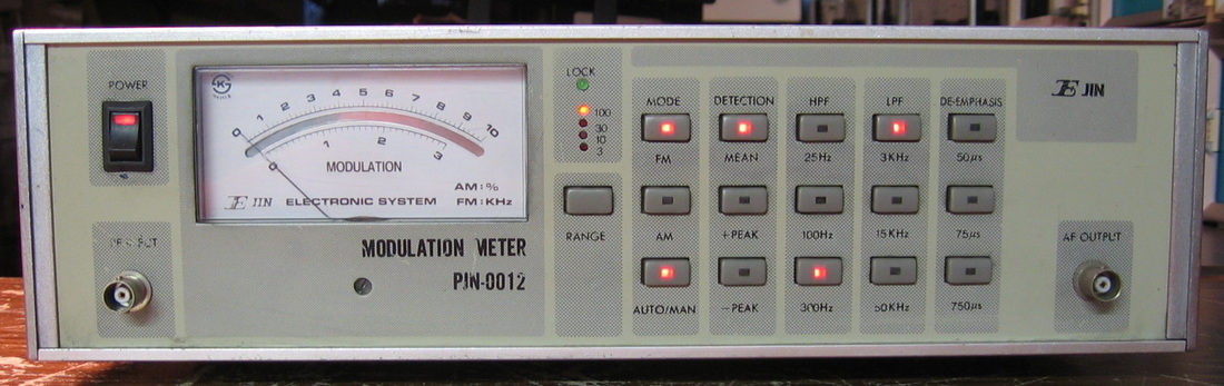
E-Jin PJN-0012: The PJN-0012 is a basic modulation meter which measures percentage of AM modulation and kHz deviation of FM modulation. It automatically locks to signals in the range of about 2 MHz to 1 GHz. Has some auxiliary functions such as high and low pass filters, de-emphasis and various peak detectors. It might be a nice unit if it didn't have the worst build quality ever seen in any piece of test equipment. Korea's finest. But it actually performs very well when the tantalums don't catch fire. Had three units; gutted one and sold the other on eBay for a few bucks. Even now, I cringe every time I turn this thing on. I can still hear faint cracks and gurgles from inside. But the meter moves right to where it's supposed to, so I can't complain. I know that this unit was built in Korea. Maybe it was North Korea? (---) Grade: C-
No schematic (of course), but one of my favorites. The repair procedure was pretty straightforward: 1) turn it on, 2) wait a few seconds, 3) find the tantalums that are on fire, 4) turn it off and replace the caps that caught fire, 5) repeat steps 1-4 until no more fires. After I replaced all the offending caps, it still had problems that were resolved by resoldering virtually all of the connections on the RF board.
No schematic (of course), but one of my favorites. The repair procedure was pretty straightforward: 1) turn it on, 2) wait a few seconds, 3) find the tantalums that are on fire, 4) turn it off and replace the caps that caught fire, 5) repeat steps 1-4 until no more fires. After I replaced all the offending caps, it still had problems that were resolved by resoldering virtually all of the connections on the RF board.
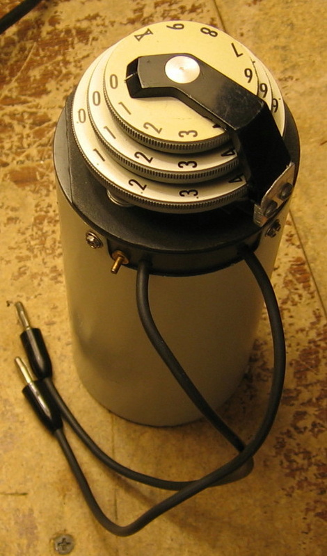
ESI CA1624: This is a "Dekastat" milli-ohm decade resistance box with a total resistance of 1.11 ohms. The three concentric dials go from 1) 0 to 1 ohms in 0.1 ohm increments, 2) 0 to 0.1 ohms in 0.01 ohm increments and 3) 0 to 0.01 ohms in 0.001 ohm increments. The residual resistance is about 0.04 ohms and must be nulled out on the ohmmeter under test. After I fixed the unit (see below), the two higher ranges were spot-on, but the lowest range was about 35% too low. In other words, the 0.001 ohm increments measured 0.0006 to 0.0007 ohms. This was verified on five different high precision DMMs as well as the HP 4328A milli-ohmmeter. Pretty perplexing because I would have thought if the switches were screwed up, the resistance would increase, not decrease. As is often the case, this page's technical adviser/editor offered the explanation: think temperature! Yup, stuck the thing in a 150 deg oven for 5 minutes and the 0.001 ohm increments measured 0.001 ohms. Then I had fun sitting on the bench aiming a heat gun at the thing. Bottom line: the thing is calibrated in my basement to 0.0006 ohms per 0.001 ohm setting until I figure out some sort of temperature control (water bath???). (---) Grade: C+
This was advertised by the seller as working, but noisy on the lowest range. He also claimed that the three wafers on the three switches were cracked. He was right, but some epoxy took care of that. I stripped off the labels, which were unreadable anyway, and gave the case a new paint job.
Postscript: The fact that all of the 0.001 ohm increments read about 0.0006 ohms has really been gnawing at me. So, what the hell, I cut open each of the ten wire resistor loops and added about 1/8" of hookup wire across the cut, fine tuning everything with the ESI SP5110 LCR meter set to R with 0.0001 ohms resolution. I did pretty well at the end of the surgery, achieving about 0.0105 ohms with the CA1624 set to the full range of 0.01 ohms on the 0.001 ohm scale (it was 0.006 ohms before). Now all my DMMs count up by 0.001 ohm as I turn the dial. Only the SP5110 and the HP 4328A milliohmmeter have enough resolution to see the discrepancy on any single resistor.
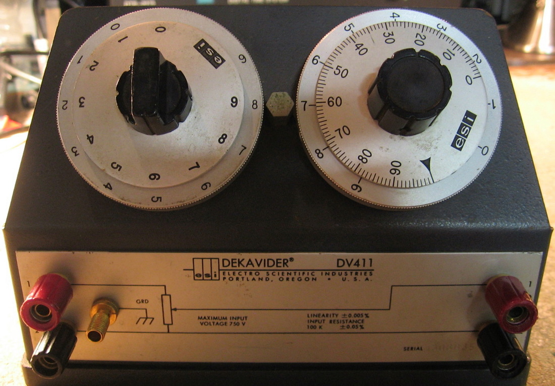
ESI DV411: 4-digit "Dekavider" Kelvin-Varley divider box. Unlike the ESI CA1624 "Dekastat," which is simply a calibrated resistor, the Dekaviders are voltage divider boxes with an input and an output. ESI made a bunch of these with progressively tighter specs (as the model number goes up). The DV411, despite an impressive linearity of 0.005%, is actually at the low end of the models. Generally, the dividers have either a 10K or a 100K input impedance. The higher input impedance models are good when you want to throw a few hundred volts at the input. But you have to be careful because the resulting heating of the resistors inside will change the resistance ratio (hence the output voltage) proportional to the unit's temperature coefficient. K-V dividers are used in conjunction with 1) a known very accurate reference voltage, 2) a stable adjustable DC source (usually a DC calibrator in its own right, but not as accurate as the reference), and 3) a null voltmeter. Doing so can transfer the accuracy of your reference to any voltage you want. Very handy for calibrating 6-1/2 digit DMMs. In fact, most calibration procedures for the various DMMs I have in my collection call for just such an arrangement. Without the Dekavider, I was simply using my Fluke 343A DC calibrator. Now, I can do it right. I've "tested' the DV411 by setting the divider ratio to 1.0, adjusting my 343A so that the DMM reads exactly 10.0 volts, and then trying the divider at ratios of 0.9, 0.8, 0.7, ..., 0.1. On my Advantest R6871E-DC 7-1/2 digit DMM, the errors I obtained for these nine output voltages were 2.2, 4.5, 7, 8.7, 7.4, 1.5, 4.7, 16, and 18.9 ppm respectively. The reason I put "tested" in quotes, is that my the Advantest DMM has probably about a 20 ppm uncertainty on top of the 50 ppm uncertainty of the DV411. But as far as I can tell, things look good. The unit is built like a tank and must weigh 10 lbs. (---) Grade: A

ESI RV622A: 6-digit "Dekavider" Kelvin-Varley divider box. This is the big brother of the ESI DV411 shown in the previous entry. Not only are there six digits instead of four, but the accuracy is outstanding: about 1-2 ppm. And they aren't kidding. You can, for instance, feed my Fluke 343A through the RV622A set to 1 (99999"ten" on the dials), adjust the 343A so that a 6-1/2 digit DMM (e.g., HP 3456A) reads 1.000000, and then start turning the RV622A knobs. Virtually every setting yields a DMM value that is within 1 microvolt of your settings. Couple this set-up with a very nice 10V reference I obtained from voltagestandard.com and my Fluke 887A as a null voltmeter, and I have an extremely accurate way to calibrate all of my DMMs (and my Fluke 343A). (---) Grade: A
My buddy and I split a purchase of 2 of these for a total of $250. He tested them both and gave me the less accurate one. But the problem turned out to be only in the 4th digit. I noticed that the 1st and 4th switches were a bit loose, so a little dissection enabled me to get to the mounting nuts and tighten them down. But the 4th digit was still acting flaky, giving me about 50 uV change just by shaking the knob. Various rinses with alcohol, contact cleaner and de-greaser was not curing the problem. I ended up isolating the few switch contacts that were giving me problems and very gently nudged them a little with a dental pick. Seems perfectly fine and stable now, and I'm getting the accuracy I deserve.
My buddy and I split a purchase of 2 of these for a total of $250. He tested them both and gave me the less accurate one. But the problem turned out to be only in the 4th digit. I noticed that the 1st and 4th switches were a bit loose, so a little dissection enabled me to get to the mounting nuts and tighten them down. But the 4th digit was still acting flaky, giving me about 50 uV change just by shaking the knob. Various rinses with alcohol, contact cleaner and de-greaser was not curing the problem. I ended up isolating the few switch contacts that were giving me problems and very gently nudged them a little with a dental pick. Seems perfectly fine and stable now, and I'm getting the accuracy I deserve.
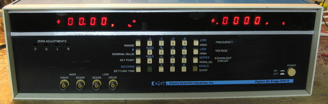
ESI SP5110: "A microprocessor controlled automatic LRC meter" says the manual for the ESI 296. Since I can find absolutely nothing about the SP5110, and it is virtually identical to the 296, we'll go with that. The left display provides reactance measurements (L and C), while the right display provides loss measurements (D, Q, S, ohms). They must be properly selected and interpreted, however. For instance, when measuring C on the left, the ohms on the right is ESR. If you want to measure a plain old resistor, you must put it into H, parallel-equivalent, and select ohms on the right display. Real intuitive, isn't it? Without the missing pull-out instruction card, figuring how to use this piece is nearly impossible. At first, I thought the unit was defective since it tops out at 200 uF. However, that seems correct since this piece has the optional 1 kHz and 10 kHz measuring frequencies, not the 120 Hz and 1 kHz standard frequencies of the 296. And it turns out that you can coerce it up to 2000 uF by entering a "special" mode from the front panel. Besides the high frequency option, mine also has the fast measuring option. This is accomplished by adding a second A/D card so the thing can do the left and right measurements in parallel. The connections to the DUT are through 4 BNC jacks, but the unit really is a 6-terminal measurement. In addition to the four center conductors that go to a Kelvin clip arrangement, the shield of the Hi Drive gets connected to the shield of the Lo Sense at the DUT - this provides a guard. There was no status description from the seller, but the thing seems to work just fine now that I know how to use it. The basic specs are 0.1% accuracy making this thing at the top of the LCR heap. And it ought to be that accurate since I counted about 70 Caddock 0.01%, 10 ppm/C precision resistors (worth about $1,000 total). I give the build quality a B+, but they didn't cut corners on parts selection. I give that an A+. (OM) Grade: A
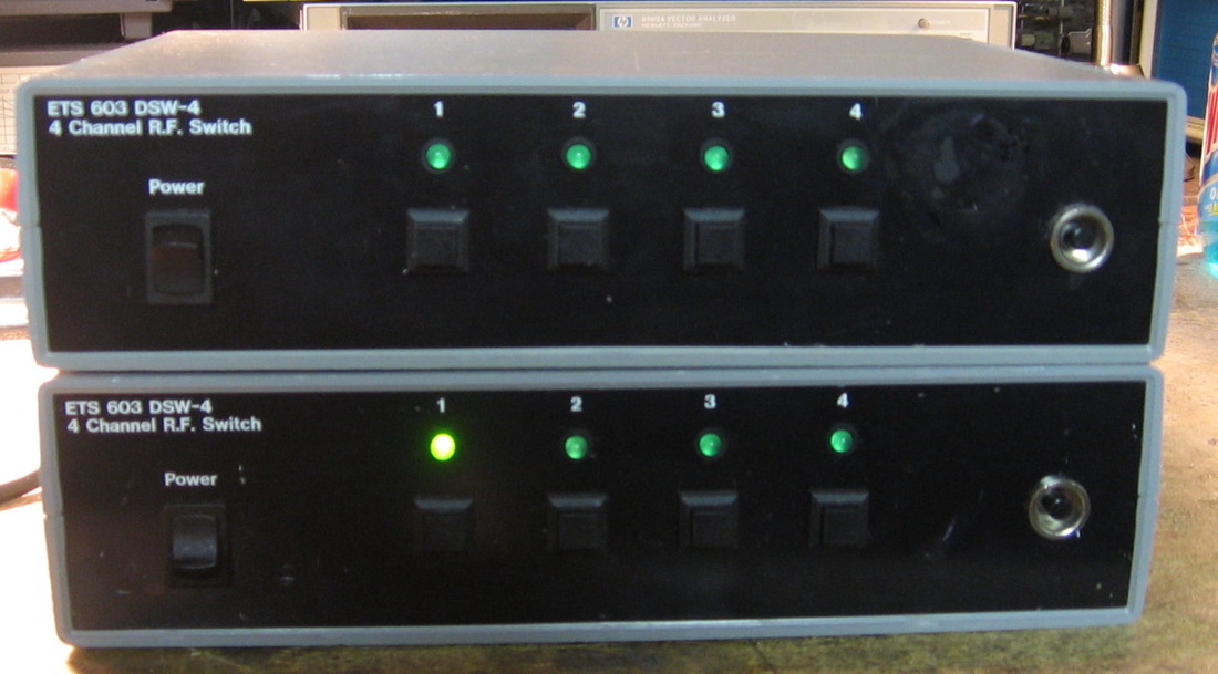
ETS-603 DSW-4: 4-channel RF switch. That's all I can find about these - namely, what it says on the front panel. I took a chance that they actually could switch a reasonably high frequency and paid $25 + shipping for a set of four of them. On the DSA-815 spectrum analyzer, they were flat to 1.5 GHz and had >90 dB isolation between the four ports. At face value, pressing one of the four buttons switches the common input (SMA) on the back panel among the four outputs (N). However, there is a pesky Ethernet jack on the back (and a MAC address label) which does me absolutely no good. Even worse is that it takes about 30 seconds from power-on for the thing to determine that there is no Ethernet signal and that it is OK to react to the front panel buttons. I proceeded to open one of the units up and found that they consist of the following: 1) a Meanwell +/-5V, 2.5A switch P/S, 2) a Rabbit RCM2100 controller board and 3) three Minicircuits ZASWA-2-50DR RF switches. Everything was hooked up with high quality semi-rigid coax and connectors. The Minicircuits data sheet confirmed that these units are good to 5 GHz. At this point, I stripped the parts out of two of the units and put all the parts up for sale on eBay. All I have to do is sell one of the Minicircuits switches to break even on my purchase! I don't know who or what ETS is, but these units look almost like a custom build for someone. The four S/Ns were 005, 007, 008 and 009. And when I was dissected them, there was still a price tag stuck to one of the terminal strips. (---) Grade: B
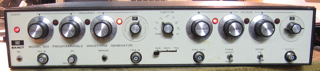
Exact 605: 1 MHz programmable waveform generator. Pretty standard stuff circa 1980. Not too sure about the "programmable," but it does have a 50-in Centronics connector on the back panel (according to the manual, applying voltages to the proper pins can control 38 of the parameters). Does the usual sine, triangle, square, ramp and pulse waveforms with three digit frequency resolution and three digit amplitude resolution. Has an invert shape function and a fixed DC offset (an arbitrary DC offset can also be supplied from an input BNC on the back panel). There are a variety of gate and trigger options and lots of auxiliary outputs on the back (more than the usual function generator). Covers 1 mHz to 1 MHz and 1 mV to 10 V with a basic accuracy of about 1%. The construction is first rate with the component values silk-screened on the boards. Exact also went the extra mile because most of the selections are made via reed relays rather than directly off the rotary switches on the front panel; there are about 60 reed relays in this thing! So, while noisy rotary switches might cause the relays to bounce, at least they don't alter the basic R-C values used throughout. Exact produced a bunch of function and sweep generators before eventually being bought by Racal-Dana and they stack up pretty well against non-HP generators of that era such as Wavetek. ($CD) Grade: B+
Advertised by the seller as "only the triangle function works." Most function generators like this charge/discharge timing capacitors to produce a triangle waveform. Then this triangle is used to produce square waves via a Schmitt trigger or sine waves via a bunch of shaping diodes. So my initial guess was that the switch routing the triangle to the subsequent circuitry was faulty. But alas, after I turned the thing on for a few minutes and exercised all the switches, everything worked fine. All the front panel switches were soaked in tuner cleaner for good measure. After a while, the unit intermittently would not select the proper waveforms (just like the seller intimated). This was traced to a fault in the massive wiring harness connecting the two main boards. I resoldered most of the connections; in particular, looking at the schematic revealed that solder point #992 was probably the likely culprit. Now, movement of the wiring harness has no ill effect. The captive line cord was also severely frayed, so that was replaced. I found the service manual for $20 and calibrated the unit. All seems in spec except that the harmonics for sinewaves >800 kHz are down only about 27 dB, not the 30 dB that is claimed. I might be able to relax the sinewave distortion adjustment at lower frequencies (which I have down to 0.23% against the 0.5% spec) and tweak the high frequency harmonics a bit. Maybe one of these days...
Advertised by the seller as "only the triangle function works." Most function generators like this charge/discharge timing capacitors to produce a triangle waveform. Then this triangle is used to produce square waves via a Schmitt trigger or sine waves via a bunch of shaping diodes. So my initial guess was that the switch routing the triangle to the subsequent circuitry was faulty. But alas, after I turned the thing on for a few minutes and exercised all the switches, everything worked fine. All the front panel switches were soaked in tuner cleaner for good measure. After a while, the unit intermittently would not select the proper waveforms (just like the seller intimated). This was traced to a fault in the massive wiring harness connecting the two main boards. I resoldered most of the connections; in particular, looking at the schematic revealed that solder point #992 was probably the likely culprit. Now, movement of the wiring harness has no ill effect. The captive line cord was also severely frayed, so that was replaced. I found the service manual for $20 and calibrated the unit. All seems in spec except that the harmonics for sinewaves >800 kHz are down only about 27 dB, not the 30 dB that is claimed. I might be able to relax the sinewave distortion adjustment at lower frequencies (which I have down to 0.23% against the 0.5% spec) and tweak the high frequency harmonics a bit. Maybe one of these days...
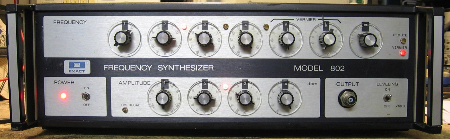
Exact 802: 20 MHz frequency synthesizer. I can't find anything online about the 802, let alone an operation and/or service manual. But I'll take a chance for $9.99. Who knows what the specs are, but it does generate sine waves. It is very similar to my HP 3320B. (---) Grade: B
Advertised as "doesn't power up despite numerous attempts." Well, how many attempts do you need? Out of the box, I noticed that the line fuse was blown. Rather than just replacing the fuse, I decided to open it up and take a look around. When I took off the covers, out plopped a one inch piece of orange/white hookup wire that looked like someone chewed it. Then I noticed that whatever rodent took residence in this piece long ago chewed through much of the insulation on the wiring from the AC receptacle to the fuse and power switch. So there was probably a short that popped the fuse. I replaced the wiring and was about to turn the piece on when I noticed that all the wiring was chewed up from the power supply to the motherboard. I unplugged the output connector from the P/S and fired the piece up - all the (open circuit) voltages were OK (luckily they were labeled). I redid all the wiring from the P/S connector and this time when I turned the piece on, the voltages were all folded back to near zero. A quick check with the ohmmeter showed a dead short on the -15V rail. By pulling boards, I isolated the short to a particular board and it was a simple matter to replace a bad tantalum cap. This time when I turned the piece on, the voltages were fine and I got some output. The output waveforms were kind of distorted but there were a couple of pots on the amplifier board that made it slightly better. Then I noticed that the amplitude controls weren't responding correctly. Like the HP 3320B, the 802 has four rotary dials for the XX.XX dBm amplitude. The tens place is done with a step-attenuator. The 1, 0.1 and 0.01 dB places are done electronically via the leveling board which develops a modulating voltage and uses a dual thermocouple to compare the rectified output against a reference. I spent a couple of days blindly adjusting pots and debugging to no avail. Finally, on the mixer/pre-amp board, I noticed that someone had paralleled a 120 ohm resistor on top of a 470 ohm resistor near the output of the board. I removed the 120 ohm resistor and put a resistor-substitution box in its place. At ~55 ohms, the unit seemed to suddenly behave. The amplitudes were (approximately) correct and I wasn't seeing any kind of waveform distortion like before. I pulled out the 470 ohm resistor and put a 200 ohm pot in its place. Given all the pots I blindly adjusted previously, it is amazing that this piece basically now works. The frequency is rock solid, the amplitudes are OK within 1/2 dB, and the waveforms look fine, with a little residual DC offset. Without a service manual, that's about as far as I can get in the way of adjustments, so we will call it a day on this vintage 1974 piece.
Advertised as "doesn't power up despite numerous attempts." Well, how many attempts do you need? Out of the box, I noticed that the line fuse was blown. Rather than just replacing the fuse, I decided to open it up and take a look around. When I took off the covers, out plopped a one inch piece of orange/white hookup wire that looked like someone chewed it. Then I noticed that whatever rodent took residence in this piece long ago chewed through much of the insulation on the wiring from the AC receptacle to the fuse and power switch. So there was probably a short that popped the fuse. I replaced the wiring and was about to turn the piece on when I noticed that all the wiring was chewed up from the power supply to the motherboard. I unplugged the output connector from the P/S and fired the piece up - all the (open circuit) voltages were OK (luckily they were labeled). I redid all the wiring from the P/S connector and this time when I turned the piece on, the voltages were all folded back to near zero. A quick check with the ohmmeter showed a dead short on the -15V rail. By pulling boards, I isolated the short to a particular board and it was a simple matter to replace a bad tantalum cap. This time when I turned the piece on, the voltages were fine and I got some output. The output waveforms were kind of distorted but there were a couple of pots on the amplifier board that made it slightly better. Then I noticed that the amplitude controls weren't responding correctly. Like the HP 3320B, the 802 has four rotary dials for the XX.XX dBm amplitude. The tens place is done with a step-attenuator. The 1, 0.1 and 0.01 dB places are done electronically via the leveling board which develops a modulating voltage and uses a dual thermocouple to compare the rectified output against a reference. I spent a couple of days blindly adjusting pots and debugging to no avail. Finally, on the mixer/pre-amp board, I noticed that someone had paralleled a 120 ohm resistor on top of a 470 ohm resistor near the output of the board. I removed the 120 ohm resistor and put a resistor-substitution box in its place. At ~55 ohms, the unit seemed to suddenly behave. The amplitudes were (approximately) correct and I wasn't seeing any kind of waveform distortion like before. I pulled out the 470 ohm resistor and put a 200 ohm pot in its place. Given all the pots I blindly adjusted previously, it is amazing that this piece basically now works. The frequency is rock solid, the amplitudes are OK within 1/2 dB, and the waveforms look fine, with a little residual DC offset. Without a service manual, that's about as far as I can get in the way of adjustments, so we will call it a day on this vintage 1974 piece.
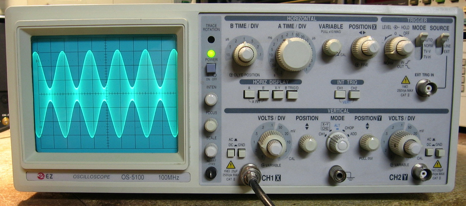
EZ OS-5100: Generic 100 MHz analog oscilloscope. EZ Digital was a Korean company which I think was bought by LG. This scope, or a close variant, is also sold under the Goldstar name and perhaps others. It is somewhat similar to my Tenma 72-3060 scope listed below (without the built-in function generator) and the boards look like they were designed/manufactured by the same company. The OS-5100 is a basic scope, suitable for the classroom and/or mild circuit analysis. It will do a dual trace (alt-chop) like most and does have a delayed time base. However, it will not show the main and delayed waveforms at the same time. You have to set it to "A Intensify" mode, dial in the intensified portion for the "B" trace, then set it to "B display" to see the delayed waveform. Kind of obnoxious. Now perhaps it is supposed to show both traces at the same time because there is a "picture" in the operations manual showing exactly that. But all my other scopes that have dual time bases and show both at once have a "trace separation" knob to control the placement on the screen. The OS-5100 has no such control, so I'm a little leery. If I had the service manual, I could take a look, but I don't. (---) Grade: B+
Advertised as not working, all I got when I turned it on was a small circular trace at the left edge of the screen. There were test point markings on the horizontal board for +5, +12 and -12 volts. The +5 was fine, but the +12 measured +15 and the -12 measured -17.5. According to the schematics I have for the closely related Tenma 72-3060, the +/-12 volt supplies are classic pass transistors controlled by op-amps. I traced the -12 volt line down to a chassis mounted pass transistor and found a C-B short. I replaced the transistor with a TIP41C and fired the unit back up. The +12 measured +12 and the -12 measured -12. And lo and behold, the scope worked perfectly. I am somewhat surprised that the unit was so messed up with the power supplies a bit out of whack. Perhaps there were some comparators in the trigger and/or horizontal circuits that relied upon a certain threshold set from these two supplies. When the supplies were wrong, the thresholds were wrong and could have prevented the thing from sweeping. We'll never know...
Postscript: The Time/Div rotary switch was a bit flaky despite several sprays of alcohol and contact cleaner. I finally disassembled the unit and pulled out the switch. I took a burnishing file and hit all of the little leaf contacts and after reassembly, the unit seems all better now.
F : Ferrograph, FLIR, Fluke, Frequency Devices, Futurekit

Ferrograph RTS-2: Multi-purpose tester for tape recorders. Has 1) sig gen, 2) AC voltmeter, 3) wow and flutter meter and 4) distortion meter. Surprisingly good given the small number of components. I bought this unit after I looked at the schematic and noticed that it had like 50 parts in it. Now I've got plenty of HP signal generators and various meters and there are hundreds of parts in each one. So how did Ferrograph manage to design such a simple circuit? Were they smart or was HP dumb? (PDF) Grade: B+
Found two faulty electrolytics and decided to replace them all.
Found two faulty electrolytics and decided to replace them all.
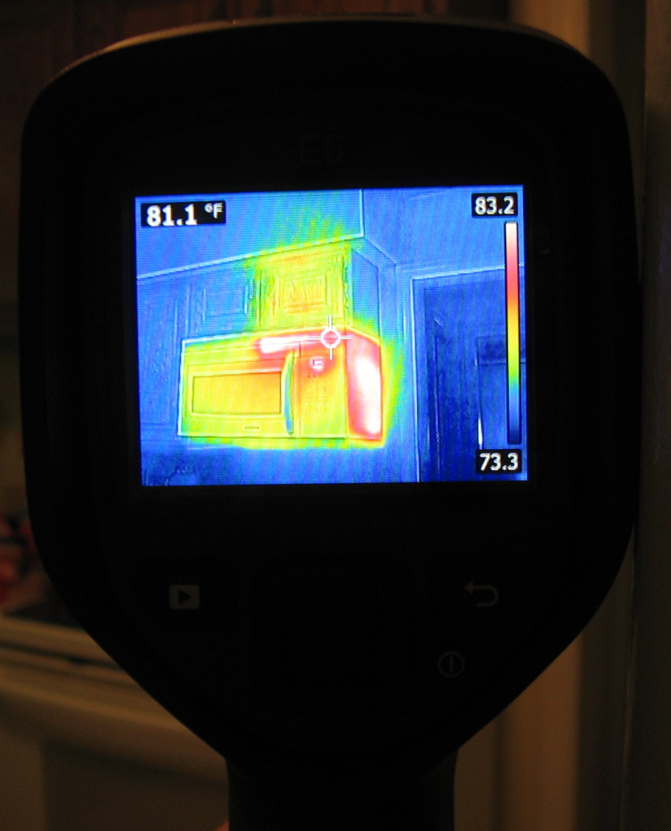
FLIR E6: Thermal imaging camera, 160x120 pixels. Came into a bit of cash so treated myself to this unit. I was going to buy the lesser E5, but I was at the right place at the right time when FLIR was having a special (unannounced in advance as far as I can tell) sale on the E6, namely $750 off. This made it only $50 more than the E5, so it was a no-brainer to get the more capable E6. Early tests with it seems to indicate it will be just fine for measuring the temps of components on a circuit board. Moreover, I can tell where all the heat/cool loss points in my house are. I know one used to be able to buy the lowest price E4 and then hack it up to the best E8 (since the hardware is basically the same). But this time, I decided not to be a low-life cheat (see the Rigol entries below) and bought the model I wanted. (PDF) Grade: A
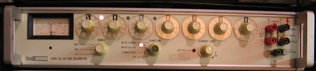
Fluke 343A: DC Voltage calibrator to >1000VDC. Courtesy of WA1MIK who supplied two non-working units. Fixed both, kept one, sold the other on eBay for over $200. A third parts unit was also sold on eBay to a buyer in Japan for about $25. I calibrated this against a newly purchased HP34401A DMM I borrowed from work. I guess that will have to do. I mean it's not like I'm running a cal lab in my basement. (PDF) Grade: A
The unit I kept had a faulty open power resistor in the high voltage feedback circuit. The second unit had several faulty electrolytic caps in the chopper amplifier circuitry. The third unit was way beyond repair.
Postscript: The main resistor string board is connected via about a dozen push-pins. These have been working loose over the years and causing some problems with the 343A, especially on the 10 setting in the left-most knob. So I dropped some solder on all the pins and the 343A seems much better. Of course, I'll never be able to remove any of the boards again.
Postscript^2: After many years, I noticed the 343A was slightly out of calibration. The cal procedure went OK except for the highest digit on the first knob. Most likely, one or more of the Fluke-made custom precision resistors in the sample string have drifted. It is not really of concern because it only effects the 10 digit and is easily worked around. For instance, if you want 10 volts, you have at least three choices: 1) 10 V range and 10 on the first knob, 2) 10 volt range and 9X on the first two knobs, or 100 volt range and 1 on the first knob. The latter two are fine; it is only the first choice that will read slightly out of spec high. So I padded one of the adjustment pots with a 100 ohm resistor. This made the distinction OK on the 10V range, i.e. 10 and 9X now read the same. Unfortunately, the discrepancy still exists on the 100V range. So I just have to be careful to use 9X when I want 100 volts, or use 1 on the first dial in the 1000V range, no big problem.
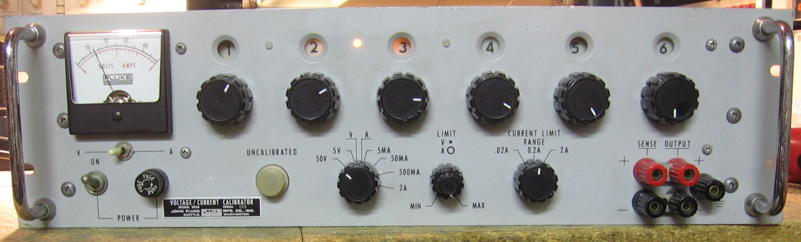
Fluke 382A: DC voltage and current calibrator: This is a relic from the past. About 1964 to be exact (although my unit was built about 1968). It will calibrate voltages up to 50 volts with 0.01% (or 100 uV, whichever is greater) accuracy and current up to 2 amps with 0.02% (or 0.002% of range, whichever is greater) accuracy. By modern standards, 0.01% voltage accuracy is pretty anemic and this unit could barely calibrate a 4-1/2 digit DMM with any certainty. Nonetheless, I'm sure it was a marvel in 1964 and cost a pretty penny, and it is nice to have a 2 amp current source (even though this beast draws about 200 watts to produce it!). My biggest complaint, however, is the output noise. With no load (or a modern DMM voltage input), the 382A produces a nice train of 3 msec, 5 mV, high frequency (>1 MHz) noise bursts at 120 Hz. Most DMMs won't be affected since the frequency is beyond their normal AC response, but it is quite discomforting to view the 382A output on a scope. The bursts aren't really that unexpected because the 382A acts somewhat like a switching power supply (and we know those things have noisy outputs). In order to keep the power dissipation on the main pass transistor low, they use an SCR to charge up a capacitor which keeps the C-E voltage to about 8 volts; this SCR fires at 120 Hz. Whether there is some fault in the unit that I haven't found (and I did try), or this thing is suppose to produce these pulses, I have no idea. It's difficult to assign a grade for this piece because it probably deserved an A in 1964, but is barely worth a C today. So I'll compromise. (PDF) Grade: B
Bought as condition unknown, the 382A fired right up and produced some output. But the numeric selection switches on the front panel were extremely intermittent and so were doused in alcohol. The thing then produced a fairly consistent and accurate output. But, as alluded in the paragraph above, when I looked at the output on a scope, I saw the noise bursts. While trying to find the source, I managed to come across a burnt diode, burnt resistor and open resistor. Those were all fixed, but did not affect the output noise. All in all, given its 50 year age, a lot more could have been wrong with this: the mechanical chopper, the electrolytics, the germanium transistors, etc.
Postscript: I knew that some sort of bypass capacitor would probably fix my high frequency noise bursts on the output. But I learned an important lesson, namely, it matters a whole lot exactly where you place such a thing. After a lot of trial-and-error, I managed to remove these bursts and now the output noise is 50 uV like it is supposed to be.

Fluke 540B: AC-DC thermal transfer standard. This is a specialty piece that was used by many labs to calibrate AC voltages. The idea is fairly simple. Take a DC standard, run it into the 540B (set to DC transfer) and null the galvanometer. Then, without touching anything, input your AC voltage (set to AC transfer) and adjust the input until the galvanometer nulls. What you have now done is "sync-ed" the internal thermocouple first to DC and then to AC. The AC accuracy that can be achieved is about 0.01% with the 540B. A similar technique to calibrate currents providing you have the proper current shunts (I don't). My unit has the earlier A54-1 thermocouple plug-in without the protection disable switch. Why it doesn't have the polarity switch (the hole on the front panel is simply plugged), I don't know. And the previous owner decided to put a neon light bulb in the front panel and then promptly didn't connect it up. The 540B has slightly better specs than my best AC voltmeter (Fluke 8506A), but, of course, is much trickier to use. (PDF) Grade: B+
Picked this piece up for twenty bucks. Pretty good deal until I realized it would cost me thirty bucks to replace all the defunct batteries. The 540B uses 20 NiCd Sub-C cells and a 1.35 V mercury cell. For the latter, I used the same technique as I did for the Keithley 602 - an LP2951 low-power, low-dropout adjustable regulator powered off of two AA-cells. It was throwing the protection relay upon turn-on, but it seems to have settled down to correct operation now. The protection circuit is extremely sensitive to leakage currents and the board was pretty corroded from the leaking batteries. It may require a more careful scrubbing than I've done already.
Postscript: The protection circuitry was sporadically malfunctioning and was cured by replacing the four 1N270 germanium diodes in the bridge leading up to the transistors firing the protection relays. In my opinion, Fluke did a pretty bad design job, because the entire protection circuitry rests upon how much voltage drop there is through the diodes when passing 10 uA of current through them. For instance, more modern silicon diodes will not function in this circuit (I know because I tried). Nor probably will most other diodes that aren't 1N270s.
Postscript^2: The protection circuitry still sporadically was malfunctioning and no matter how hard I tried, I could not get to the bottom of the problem. Apparently there is some leakage somewhere and I am beginning to think that it is coming directly from the board material itself. No matter, because I replaced the protection circuit with an op-amp acting as a comparator (I used positive feedback to make the protection circuit latch up like on the original). Seems to work great.
Postscript^3: The "seems to work great" ending of the previous Postscript was a bit optimistic because the 540B started throwing the protection relay when turned on with no input. I ripped out my comparator circuit and restored everything to original. Obviously, this did not fix the problem. I removed the board and noticed some very strange resistance measurements. For instance, with certain parts removed such that a particular trace was totally isolated, I got about 250K ohms resistance to an adjacent trace. This time, rather than the simple alcohol rub I gave the board when I first acquired the unit, I really went to town with a Brillo pad, muriatic acid and a toothbrush. This seems to (keep your fingers crossed) finally have fixed the protection circuit. I also bought the A54-2 plug-in thinking that maybe my A54-1 plug-in was the culprit. In retrospect, it wasn't, so now I have two plug-ins for the unit. The A54-2 required some switch cleaner to get that functioning properly.
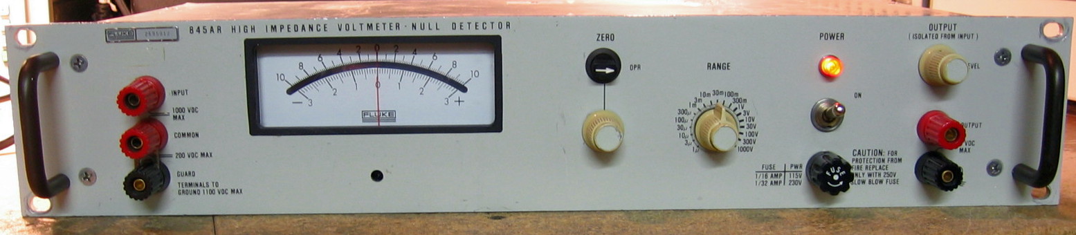
Fluke 845AR: DC null voltmeter. Measurements from 1 uV to 1100 V in 19 ranges. This is what you need if you want to calibrate a DC voltage to a standard. Hook both up differentially and tune for a null. If you look at virtually any calibration procedure from the 1970s and 1980s, you will see the 845 called out in the equipment list. Because unless you have an 8-1/2 digit DMM, this is the way everybody does it (and did it for decades). My unit is the rack-mount version which differs in form factor from the 845A and 845AB (the latter has batteries). Mine wanders a little (about 1/3 uV) but that's not bad given the age (late 1960s) and the amount of rework done to the piece. Could probably benefit from a thorough board cleaning. [Note added later: after a thorough scrubbing of the range resistors, the drift is substantially better]. (PDF) Grade: A-
Sold as dysfunctional, it certainly was when I got it. The meter was totally dead, unresponsive to any input on any range. I will compress about a week's worth of debug for you. The previous owner(s) had already replaced the two neons (used in the chopper AC amplifier) and several of the electrolytic capacitors. Thanks for that, but what took a while to realize is that he replaced almost all of the transistors. And what a replacement indeed! For not only did he not use what is called out in the parts list, but he also threw in a few PNPs where NPNs should go, and vice versa. There are several transformers in the unit used to chop the signal - these used (now unobtainable) germanium chopper transistors (chopper transistors have higher Vbeo specs). People on eevblog have recommended suitable silicon chopper transistor parts, so that is what I used. But even when I had all of the transistors correctly installed, the thing was way off on positive inputs and zero on negative inputs. The culprit seemed to be my observation that circuit ground was not propagated from the power supply throughout the rest of the circuit. I have absolutely no explanation for this. No wires seem to be missing and no traces were cut. You can follow the ground trace from the P/S and it abruptly dead-ends with the remaining circuit grounds isolated. Obviously there was some wire somewhere that got removed without leaving a trace. So I jumpered the two grounds together and now all is well.
Sold as dysfunctional, it certainly was when I got it. The meter was totally dead, unresponsive to any input on any range. I will compress about a week's worth of debug for you. The previous owner(s) had already replaced the two neons (used in the chopper AC amplifier) and several of the electrolytic capacitors. Thanks for that, but what took a while to realize is that he replaced almost all of the transistors. And what a replacement indeed! For not only did he not use what is called out in the parts list, but he also threw in a few PNPs where NPNs should go, and vice versa. There are several transformers in the unit used to chop the signal - these used (now unobtainable) germanium chopper transistors (chopper transistors have higher Vbeo specs). People on eevblog have recommended suitable silicon chopper transistor parts, so that is what I used. But even when I had all of the transistors correctly installed, the thing was way off on positive inputs and zero on negative inputs. The culprit seemed to be my observation that circuit ground was not propagated from the power supply throughout the rest of the circuit. I have absolutely no explanation for this. No wires seem to be missing and no traces were cut. You can follow the ground trace from the P/S and it abruptly dead-ends with the remaining circuit grounds isolated. Obviously there was some wire somewhere that got removed without leaving a trace. So I jumpered the two grounds together and now all is well.
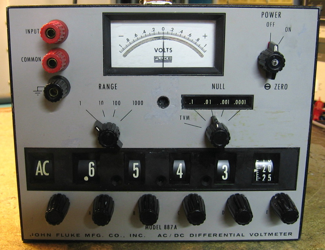
Fluke 887A: AC/DC differential voltmeter, 0 to 1100V, accuracy of 0.005% (DC) and 0.05% (AC), AC response 5 - 100 kHz. Fifty years ago, before the advent of modern six or seven digit digital voltmeters, this was how you made precision voltage measurements. The circuit conceptually is very simple. Put an ammeter between your input and the internally generated reference and adjust the reference, through a Kelvin-Varley divider, until the meter is zero. No input current is drawn when the input equals the reference, which is really the only "advantage" of a differential voltmeter: at null, the input impedance is infinite. But I have several modern DVMs with input impedances of 10 Gohms, so I guess when I measure the 9V battery in my smoke detector, I will have to settle for a reading of 8.9999999991 volts. (PDF) Grade: B+
This piece was a real mess when I received it. But like many others, all it really needed was a thorough cleaning, lubrication and calibration. When I went to calibrate it, I noticed that things weren't matching the manual. Turns out that this unit, which with a S/N of 112 may have been a pre-production model, was retrofitted at a later date by an op-amp based detector board, replacing the mechanical chopper amplifier. Lucky for me that the op-amp, an OPA111BM, was good because they sell now for about fifty bucks. I "interpreted" the manual's calibration procedure and everything went smoothly. I'm easily beating the 0.005% DC spec at this particular moment (subject to change). The front panel of this piece was particularly bad with some sticker residue unlike any I have ever dealt with. And thanks, Fluke, for painting numbers on the dials with paint that flakes off if you so much as look at it.
This piece was a real mess when I received it. But like many others, all it really needed was a thorough cleaning, lubrication and calibration. When I went to calibrate it, I noticed that things weren't matching the manual. Turns out that this unit, which with a S/N of 112 may have been a pre-production model, was retrofitted at a later date by an op-amp based detector board, replacing the mechanical chopper amplifier. Lucky for me that the op-amp, an OPA111BM, was good because they sell now for about fifty bucks. I "interpreted" the manual's calibration procedure and everything went smoothly. I'm easily beating the 0.005% DC spec at this particular moment (subject to change). The front panel of this piece was particularly bad with some sticker residue unlike any I have ever dealt with. And thanks, Fluke, for painting numbers on the dials with paint that flakes off if you so much as look at it.
Fluke Old-Time Bonus Rant: So now I have "experienced" the Fluke 343A, 382A, 540B, 845AR and 887A. These were probably marvels back in the 1960s and it is pretty impressive that they all still "work" some 50 years later. But I have found them particularly problematic to work on. Fluke probably did the best they could with the available technology, but this meant some non-standard designs that are difficult to understand. And when components do drift, as they would be expected to after 50 years, good luck trying to find the resultant subtle problems. Not to mention various parts that are now unavailable - and it is questionable whether a modern substitution will even work or simply uncover a skeleton that Fluke buried in the closet 50 years ago. It's somewhat of a shame, because some of these pieces are still very useful today.
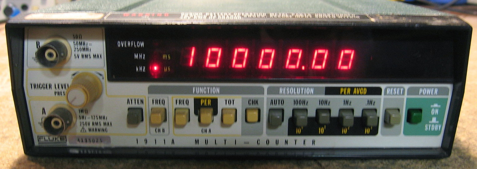
Fluke 1911A: Basic 7-digit 250 MHz counter. The 1910A (125 MHz), 1911A (250 MHz) and 1912A (520 MHz) are Fluke's entry level counters. Anyone who has any experience with frequency counters will quickly find these pieces quite lacking. Does frequency, period and totalize with 0.01, 0.1, 1.0 and 10.0 second gates. That's about it. The basic counter will do 125 MHz, but my 1911A (and the 1912A) have pre-scalers which extend the frequency range. Sensitivity is OK at about 15 mVrms. The only advantage of my 1911A is that it has rechargeable batteries, so the counter can be easily transported to where you need it and run for ~4 hours on battery (according to the manual). The build quality can be summed up in one word: cheap! For instance the front panel 7-digit LEDs are mounted on a flex board; Fluke was too cheap to even use a real printed circuit board. The fuse for the battery charger circuit is a piece of #42 wire soldered across two pads on the bottom of the board. And my unit has their best timebase oscillator option which isn't even ovenized (it's just a TXCO). Amazing that Fluke had the audacity to charge $1,380 for the 1911A in 1990. (PDF) Grade: C+
Two of these in unknown condition were bought for $20 total. The four NiCd D-cells (manufactured date 1986) in each were obviously dead, so I removed the batteries and hooked up the two pieces to an external P/S. Unit #1 worked fine once the front panel switches and the back panel internal/external oscillator switch were cleaned. Unit #2 was pretty much locked up and the fault was isolated to the custom Fluke IC controller chip. Putting the controller from Unit #1 into Unit #2 made Unit #2 functional, so that confirmed the fault. Unit #2 was therefore deemed non-repairable and instantly became a parts unit. Four of the eight NiCd batteries looked like they would accept a charge, so they were installed into Unit #1. We will see how long they hold a charge. I don't particularly want to purchase four new batteries, but batteries need to be in the unit because they serve as the 5 volt regulator.
Postscript: One day the 1911A wouldn't count except on the totalize function. This usually means the main controller, U6, is fried. But the 1 MHz clock going into U6 was absent, and the 10 MHz clock that drives the 10:1 divider supplying this clock also looked anemic. After an hour or two of pointless debug, I squirted some cleaner into the back panel oscillator int/ext switch. All seems perfectly fine now.
Postscript^2: The contact cleaner in the back panel oscillator int/ext switch was only a temporary cure because some many months later, the same problem occurred. This time, I unsoldered the switch and took it apart. It had essentially corroded into dust. I threw the switch away and because I didn't have a suitable replacement, I just permanently wired the circuit board for internal oscillator operation.
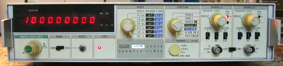
Fluke 1953A: Basic, no frills 125 MHz counter. There about a dozen options that can fit inside. Mine has none of them. However, it counts like a counter should and is worth about the $20 I paid for it. (PDF) Grade: C
The seller advertised this piece as "powers up, non-responsive to input," and that's exactly how I found it. The counter is based on an LSI counter chip and if that is toast, fugetta bout it. Probing with the scope showed pulses going into the chip but all output lines at zero. But then I discovered that the update and reset lines going to the chip were not toggling. After grounding them and seeing output on the display, that proved the LSI chip wasn't the problem. Tracing back through the circuit, Fluke used a 5-bit shift register to propagate various timing signals to the counter chip. Seeing TTL levels at 2V coming out of that shift register wasn't a good sign, so the 74LS96 chip was replaced and the counter now works fine. Well it did for a couple of weeks until the sixth digit's LED went dark. That was caused by a faulty driver transistor.
Postscript: Several years later and the 1953A is not counting. Tracing through the signal flow led me to a 74LS02 that was acting strangely. The chip was one of only a few that were socketed and the problem was cured by reseating the chip. I'm not sure whether the socket was original equipment (probably not) or added by the previous owner. But it is a very cheap socket and I probably should have removed it and soldered the 74LS02 to the board. Maybe next time.
Postscript^2: Went looking for something to fix, so I powered up the 1953A. Although the self-test ran fine, all the displayed frequencies of any input signal were about 13% low. I checked the 10 MHz clock and it was 13% high, so no wonder. Turns out that the 10 MHz TXCO was only receiving about 1V, not the expected 12V. I'm surprised it even oscillated at all. Anyway, years ago I replaced the int/ext clock switch on the rear panel with a junkbox switch which now failed. So I removed the switch and permanently wired the thing for internal clock only.

Fluke 5200A: AC calibrator, 120 Vrms, 1.2 MHz. A real beast. It is my AC "standard" despite the fact that I have nothing that can calibrate it. Fluke offered a matching amplifier for higher voltages if you like vacuum tubes. (PDF) Grade: A
The unit would not properly start up when received. This was traced to a faulty 2N3906A in the interrupt circuit. It also had a distortion problem that abruptly started at frequencies > 800 kHz. A 10 pF snubber capacitor was cleverly added on the oscillator board to squelch that. I also had to rebuild a couple of the wafer switches since the cardboard-like material had warped pretty badly.
Postscript: When I last tried to use the 5200A to calibrate a Solartron 7050 DMM, I noticed a burnt resistor odor emanating from the unit. And, of course, the unit had no output. Smelled like a P/S problem to me. The 5200A has 9 independent sub-supplies and it was fairly easily to spot the shorted tantalum capacitor on the -15V output of one of the dual +/-15V sub-supplies. Replaced the tantalum (actually I replaced both the -15V and the +15V tantalums) and the burnt current limiting resistor in series with the -15V pass transistor. Good as new.
Postscript^2: Fast forward a year or so and I noticed that the 5200A was no longer accurate or stable. Dial in 1 VAC and you would get something like 0.9xxxxx, where the last five digits were gyrating rapidly. The 5200A is one giant loop: oscillator --> amplifier --> attenuator --> AC voltmeter A/D --> oscillator control --> oscillator --> etc. Something wasn't stable and no matter where I measured, I saw the instability. Not surprising given that I am measuring within a loop. So I "broke" the loop apart and measured things with various external stimuli. The instability seemed to be coming from the AC voltmeter A/D board. This circuit is the usual charge/discharge an integrating capacitor. I've seen those caps go bad and create similar havoc, even though the caps test OK on a component analyzer. So I replaced the cap. While doing that, I temporarily removed and reinstalled a plug-in daughterboard. Bottom line is that the 5200A now works perfectly. Whether it was the cap or simply dirty contacts to the daughterboard, who knows. Incidentally, while I was testing the fix, I noticed that the 5200A was stable across one hour (at 1 VAC, 1 kHz) with a standard deviation of about 1 uV. The 1 ppm stability rivals that of the three-oven Fluke 5440B DC calibrator and is almost too good to be true, but it seems so.
Postscript^3: Another day, another shorted tantalum. This one was on the optional GPIB board and dragged the 5V line to zero. I also replaced the tantalum on the P/S regulator board for the 5V supply since that one was discolored and not long for this world.

Fluke 5440B: DC voltage calibrator. While my other calibrators (Fluke 343A and EDC 501) offer 20 to 30 ppm accuracy and are considered fine for the home user, the Fluke 5440B is about an order of magnitude better and is intended for calibration labs or equipment manufacturers. It will do up to 1,100 volts and 25 ma (later models will do 65 ma) and includes a way to set up a sequence of output states and a non-volatile memory pack to save them. For lower voltages (<2.2 V), one can switch the unit into a "divided" mode - this, supposedly, offers a little better stability. However, other users report that the divider doesn't stay in calibration nearly as long as the normal mode. And speaking of calibration, the 5440B has an internal cal function that aligns things with its internal reference. External cal is required if one wants to set the reference, however. The unit itself is massive (65 lbs) and the insides are fairly well built. The outside is typical Fluke - a flimsy case and minimal supporting structure. Functionally, this thing is essentially a voltage standard feeding a PWM D/A converter feeding a summation op-amp. But seeing as there are 3 separate ovens, 20 boards, ~25 relays, 37 fuses, 2 separate microprocessors, elaborate self-test capability, etc, etc., etc., I think there is a little more to it. One thing I don't like is the clunking of relays. Every time I hear them, I count one more towards their eventual end-of-life. Nor do I particularly like the settling time - for instance, changing voltages (within the 0-22V ranges) guarantees 7 ppm accuracy after 3 seconds, 2 ppm after 5 seconds and 0.5 ppm after 10 seconds. So you need to give the 5440B plenty of time which can be a bit annoying if you are stepping through a long DMM calibration sequence for example. Warm-up time is pretty good, however. From a cold start, my unit is about 37 ppm low (at 10V) and reaches a stable output in a little more than 30 minutes. (PDF) Grade: A-
This piece was offered at $1,000, but I got it for $500. Still, an enormous sum for my liking. The photo showed it powered-up and throwing the error, "Board Ack Fault: Check Preamp Board." There is a simple circuit on each board that decodes a specific address and pulls an ack line down. So I figured it must be something simple. But when I received it, it wasn't throwing any errors and passed the digital self-tests. So I punched in 1.0 volts and let her rip. The output was a very nice and stable -16.7 volts. And it remained at -16.7 volts regardless of the voltage setting on the front panel. When I started pulling out boards to take a look, I noticed two empty relay sockets on the A9 D/A board. D'oh. While I was contemplating how much money it was going to cost me to replace two 6PDT relays, I figured I could at least jump them in the normally open mode (which would be fine as long as I didn't enter a negative voltage). But that had no effect on my -16.7 volt problem. And when I went to put the board back, I saw the two relays wedged beneath the adjacent board. So they had simply fallen out of their sockets because the previous repairman forgot to install the hold-down clips. Anyway, I traced the -16.7 volt problem to a faulty OP07 op-amp on the D/A board. With that fixed, I started to get reasonable outputs. But when I ran the analog self-test, it failed with a message to check the current limiting circuitry on the A4 output board. I could find nothing overtly wrong, so I tried a simple experiment. Set the thing to current limit at 10 ma and cranked up the voltage on a 150 ohm load until the 5440B tripped - which was at 16 ma, not 10 ma. Bottom line: there are two versions of the output board - one will do about 50 ma (with a 25 ma limit on the front panel) and one will do 80 ma (with a 65 ma limit on the front panel). Mine had the later board, but the firmware must have been earlier. So its self-test was getting a number off by a factor of 1.6. I simply replaced the 50 ohm current limiting resistors on A4 with 80 ohms and the thing happily passed the self-tests. Finally, only two out of the three ovens were working. It is a very simple circuit with some op-amps measuring thermistors and supplying voltage to a Darlington pair to drive the resistive heater. Except none of the voltages made any sense. The final MJE3055 drive transistor also didn't make any sense since it seemed to hooked up in reverse according to the data sheets. After I made an inquiry to eevblog, I got my answer. They made the MJE3055 in a TO-220 and a TO-127 case. The former has pinout B-C-E and the latter has pinout E-C-B. The previous repairman put in a TO-220 where he should have put in a TO-127. He also did this on a MJE2955 nearby. An easy mistake, and I probably would have done the same, but it really screwed things up. Flipping the transistors got the third oven fired up.
Postscript: It is clear to me that either this piece has had extensive repair/rework over its lifetime, or has been pieced together from multiple spare units. In particular, one of the A9 relays that fell out was not a 6PDT, but rather a 4PDT. Moreover, the 4PDT does not have the standard Form C pinout I would have expected. Yet the socket is wired so that either this 4PDT relay or the correct 6PDT will work. These relays are used to switch the 13V reference polarity into the D/A - a simple DPDT relay would have sufficed. But Fluke actually used a total 10 relay poles to make the switching redundant and low resistance. So my unit only uses 8 poles rather than 10. Close enough.
Postscript^2: Haven't used this piece for about six months, so when I finally did turn it on, it rewarded me by slowly climbing through 1 volt to about 1.001 volts for a 1 volt setting. Well, the resultant 1000 ppm error is only about 1000 times what it should be, so I guess something is amiss! It slowly got better after several internal cal runs were made, but it still was about 400 ppm off at 1 volt. Moreover, when set to 0 volts,
the output was about 0.5 mV. I spent half of a day puttering around with various test points, but it finally dawned on me that the relays were more likely the culprit, especially as it seemed to be getting better the more I exercised the thing. Finally, I removed all 25 relays and tested them (both NO and NC). Quite a task seeing as most are 6PDT relays. I found a half dozen contacts with resistance >10 ohms and a couple that were actually infinite. After multiple burnishings, all the relays tested fine and the unit now seems to be operating properly. Note that Fluke doubled, tripled and quadrupled up most relay contacts, so an occasional bad contact shouldn't really matter. I didn't take careful note of the bad contacts, but perhaps I got unlikely and an actual circuit was truly compromised. Anyway, I think the moral to the story is to use this piece once a week.
Postscript^3: After my relay burnishing, the 5440B was still misbehaving quite a bit. There was a substantial amount of drift and the thing would not return to the same voltage after exercising a lot of the relays with different settings. There are 25 relays (four 2PDT, five 4PDT and sixteen 6PDT). I decided to replace them all. Of course, the correct relays would set me back somewhere in the vicinity of $1,000, so that was out of the question. Instead, I purchased 62 DS2E-S-5VDC DPDT relays (4x1 + 5x2 + 16x3 = 62) for $72. These are the relays used in the subsequent Fluke 5700-series calibrators and if they were good enough for Fluke, they're good enough for me. All of the 25 relays and their sockets were removed and the 62 relays turned upside down and individually wired to the boards. These relays consume 1/4 the power of the old ones, hence run a lot cooler. Moreover, they make hardly any noise. See below for a picture of one of the boards! As an added bonus, I decided to preserve the VFD since the majority of the time, the 5440B is just turned on either at a particular voltage or to simply warm up. A small toggle switch was mounted to the front panel and the switch wired to interrupt the 29V and 5V lines coming from the control board to the display board (via a ribbon cable). Now I can run the unit all day long without feeling guilty that I am slowly killing the fluorescent display. So far, the repairs have much improved the unit. However, there may still be something wrong that I have not discovered, since I can do the internal cal procedure one day and the next day the unit will be 20 ppm off (at 1 V). Fluke recommends daily internal cals, so I think the right way to use this piece is 1) turn it on, 2) wait about 4 hours, 3) run the internal cal, and 4) use it shortly thereafter. I might take another look at the three ovens, however. Perhaps the temperature is not being correctly maintained. Stay tuned...
Postscript^4: Things have settled down now and the 5440B will reliably start-up and reach very close to the same voltage after the warm-up period. But you really do have to wait several hours for everything (including the Keithley 2015 that I am measuring the voltage with) to stabilize.
Postscript^5: One of these days, this thing will actually work correctly! The latest symptom is that even after a 4 hour warmup and an internal calibration, the unit will then drift 20 uV over the next hour or so. I thought that was bad enough until one day, after sitting at 1.0 volts for a while, it suddenly (and I mean in a few milliseconds), jumped to about 0.95 volts. Resetting the unit brought it back to 1.0 volts again, but only for a short amount of time (a minute or so), and then back down it would drop. I hooked up four 6-1/2 digit DMMs to the 1) reference, 2) DAC, 3) pre-amp and 4) output circuitry. When the voltage dropped, there was no change to either the reference or the DAC. So that means the most likely culprit is the pre-amp board (or possibly the output board). Moreover, rapping on the oven of the pre-amp board caused it to change from 0.95 back to 1.0 and back to 0.95 with repeatability. I dissected the oven and re-soldered the six wire connection to the little auxiliary differential amplifier board inside, and cleaned the connector on the other side. No more voltage change when hitting the oven, and after a 90 minute warmup and an internal calibration, the 5440B only drifted a few microvolts in the subsequent 90 minutes. We will keep an eye on it for sure.
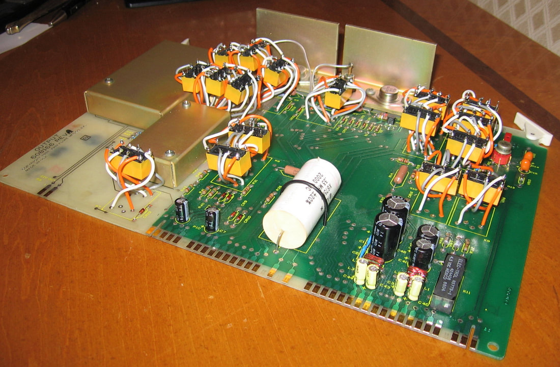

Fluke 6060B: RF signal generator to 1050 MHz. This generator is very similar to the HP 8656/7 series, although the HP ones have slightly better specs. Like HP, Fluke made a variety of models. Or should I say Gigatronics? The 6060B is also sold as the Gigatronics 6061A and although the printed circuit boards say Fluke on them, the warranty stickers on the various internal cover plates say Gigatronics. The piece will do 10 kHz to 1050 MHz (in 10 Hz increments) at 13 to -127 dBm power levels and has the usual AM and FM modulation. A nice feature is that the display can be turned off. I wish all pieces with vacuum fluorescent displays had this life-preserving feature. The buttonology is similar to HP's, so it all boils down to whether you like green or red numbers (HP) or blue numbers (Fluke) on your display! (PDF) Grade: A-
There was a nice red tag on this unit saying "fails amplitude modulation, harmonics and level accuracy." When I first turned it on, I set it to 100 MHz, 0 dBm, and everything looked perfectly fine. It wasn't until I reached 245 MHz that I realized what the red tag was referring to. The 2nd harmonic was, for instance, a mere -3 dBc. The amplitude did not follow the front panel settings and the AM-modulated spectrum looked like it was being overdriven. But first, a digital problem. While I was working on this piece, the display suddenly lost one digit, all the horizontal segments in the remaining digits, and the front panel was totally locked up. Fixing that was fairly easy - a faulty 74LS245 transceiver on the controller board. Now, back to analog. I started to march through the signal flow until the sinewave suddenly looked distorted. This occurred in the 2nd stage of a 3-stage 20 dB amplifier. It looked as though the stage wasn't amplifying, and since this 20 dB amplifier was after the ALC of the unit, my guess (which turned out to be correct) was that the ALC was trying to compensate and overdriving the hell out of the signal - hence the harmonics. To make a long story short, the 150 ohm collector resistor of the 2nd stage's transistor had decided to change to a 750 ohm resistor. This starved the amplifier and whatever was left went class C, which of course only added to the distortion. So a single faulty resistor ended up bringing this piece to its knees. Now the 150 ohm resistor has to dissipate about 1/3-watt and they used a 1/2-watt resistor which gets pretty hot. My guess is that it basically cooked itself. I got some 2-watt jobs and I put them in (they are used both in the 1st and 2nd stages). Finally, I should remark about the guts of this unit. When I first took off the top cover, I thought half of the unit was missing. All you see is one enormous metal cover plate (with about 40 screws) and this plate is half-way down to the bottom. The construction uses essentially two massive boards, each winding their way through a bunch of metal bulkheads, with a single cover plate. The boards are back-to-back, so there is one facing the top and one facing the bottom. The whole sandwich is only a few inches tall. So that leaves enough space inside the chassis to fit an entire second signal generator. The boards themselves are easy to work on from the top. Which is fortunate, because pulling a board looks like a real chore. The bottom board, which is the one that had the fault, is particularly nice since the various components in their little compartments are organized just like the block diagram.
There was a nice red tag on this unit saying "fails amplitude modulation, harmonics and level accuracy." When I first turned it on, I set it to 100 MHz, 0 dBm, and everything looked perfectly fine. It wasn't until I reached 245 MHz that I realized what the red tag was referring to. The 2nd harmonic was, for instance, a mere -3 dBc. The amplitude did not follow the front panel settings and the AM-modulated spectrum looked like it was being overdriven. But first, a digital problem. While I was working on this piece, the display suddenly lost one digit, all the horizontal segments in the remaining digits, and the front panel was totally locked up. Fixing that was fairly easy - a faulty 74LS245 transceiver on the controller board. Now, back to analog. I started to march through the signal flow until the sinewave suddenly looked distorted. This occurred in the 2nd stage of a 3-stage 20 dB amplifier. It looked as though the stage wasn't amplifying, and since this 20 dB amplifier was after the ALC of the unit, my guess (which turned out to be correct) was that the ALC was trying to compensate and overdriving the hell out of the signal - hence the harmonics. To make a long story short, the 150 ohm collector resistor of the 2nd stage's transistor had decided to change to a 750 ohm resistor. This starved the amplifier and whatever was left went class C, which of course only added to the distortion. So a single faulty resistor ended up bringing this piece to its knees. Now the 150 ohm resistor has to dissipate about 1/3-watt and they used a 1/2-watt resistor which gets pretty hot. My guess is that it basically cooked itself. I got some 2-watt jobs and I put them in (they are used both in the 1st and 2nd stages). Finally, I should remark about the guts of this unit. When I first took off the top cover, I thought half of the unit was missing. All you see is one enormous metal cover plate (with about 40 screws) and this plate is half-way down to the bottom. The construction uses essentially two massive boards, each winding their way through a bunch of metal bulkheads, with a single cover plate. The boards are back-to-back, so there is one facing the top and one facing the bottom. The whole sandwich is only a few inches tall. So that leaves enough space inside the chassis to fit an entire second signal generator. The boards themselves are easy to work on from the top. Which is fortunate, because pulling a board looks like a real chore. The bottom board, which is the one that had the fault, is particularly nice since the various components in their little compartments are organized just like the block diagram.
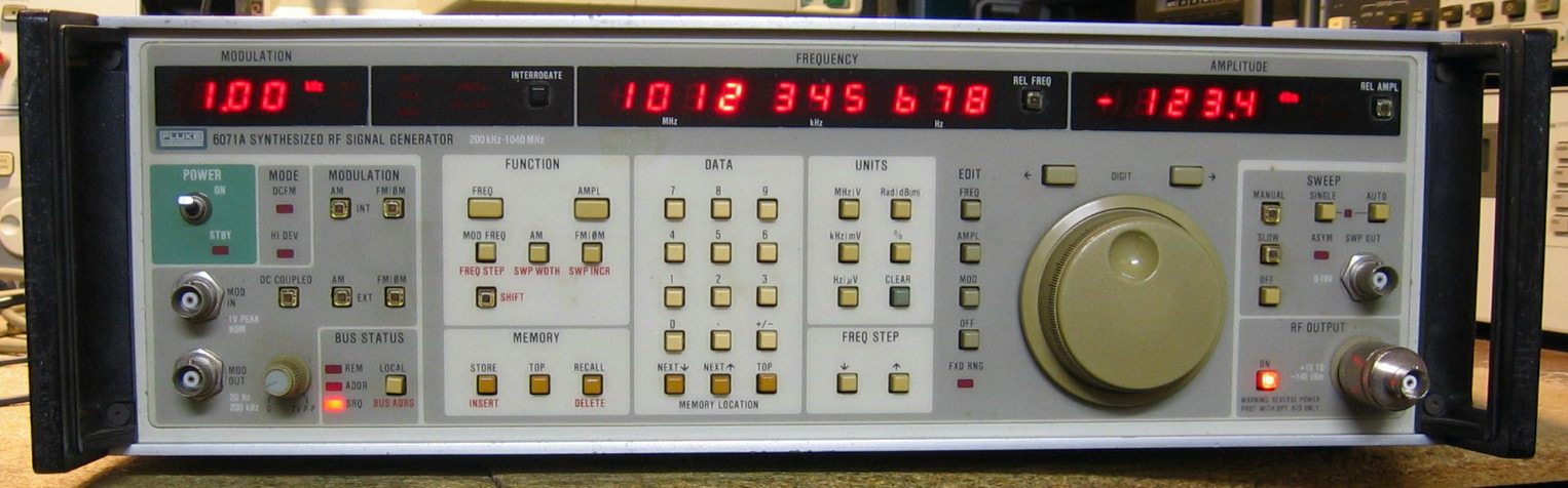
Fluke 6071A: High fidelity RF signal generator to 1040 MHz, amplitudes from -140 dBm to +19 dBm (<520 MHz) or +13 dBm (>520 MHz). Mine has the OCXO option, the non-volatile storage option, the auxiliary rear output option and the reverse power protection option. This puppy, as configured, would have set you back more than $20,000 back in 1988. Does the usual AM/FM/phase modulation. This piece was received as a gift, so I haven't really done too much research on it, but I expect it to be on par with a medium HP signal generator like my HP 8657A I do know that it uses a lot of very sensitive circuitry for low spurious emissions and phase noise; the service manual is full of disclaimers saying that the unit must be returned to Fluke for any adjustments, as they have a bunch of programmed calibration constants stored in ROMs throughout. My guess is that the specifications are somewhere between the Fluke 6060B and Fluke 6080A, which I also have. Makes sense, since the model number is between those two!!! It has an earlier look than the 6060B and 6080A, which I believe were made by Gigatronics anyway. One of these days, I will take the covers off and inspect the 6071A. But for now, it is a working 65 pound beast of a signal generator. The 6071A probably deserves a grade of A-, especially if you were to grade it in the mid 1980's when it was built, but the inability to repair and recalibrate as well as the somewhat funky front panel knobology deserves a slight demerit. (PDF) Grade: B+
There is nothing wrong with this unit as far as I can tell. However, it always powers up to the default setting of 300 MHz, -10 dBm. The back panel has a check mark next to the non-volatile storage option label, so I figured it must be the 3V Lithium battery that was dead. After reading the very confusing (and incorrect) disassembly procedure in the service manual, I pulled the front panel unit apart since that is where the uP and non-volatile storage boards live. However, the non-volatile storage board was nowhere to be found. Guess I don't need to buy a new battery after all. Note: In retrospect, I probably did not need to disassemble the unit since the service manual indicates it would have thrown an error upon start-up if there was something wrong with the optional non-volatile storage board.
Postscript: Turned it on one day and it powered itself down after a few seconds. Then pretty much nothing upon successive power cycles. I took off the covers and was staring at it trying to figure out how I was going to dissect the (sealed) P/S. I then switched the power on and it sounded like the switching power supply was trying to start, but shutting down on an overload due to a short somewhere. After about one minute, it powered up successfully and threw a lot of smoke out near the side by the front panel. Dissecting the front panel, I found a burnt tantalum, C10 (22 uF, 16V) on the controller board. Replaced the cap, but there are dozens on that board and probably hundreds scattered around the rest of the unit, so I think similar faults are likely to occur in the future.
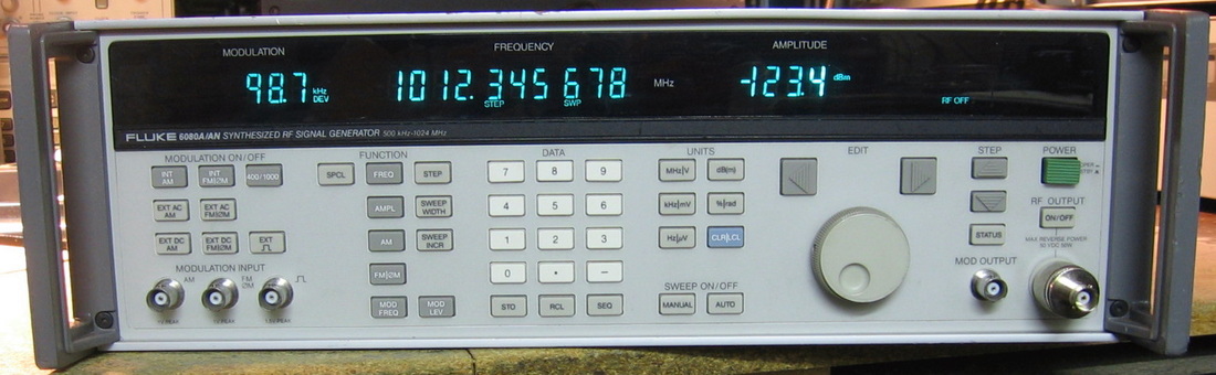
Fluke 6080A: High fidelity RF signal generator to 1050 MHz. Fluke built their 6060/2 models to compete with the HP 8656/7 series. They then built their 6080/2 models to compete with the HP 8642A/B. The 6080A is akin to the 8642A (frequency to 1 GHz, without the 2 GHz doubler) and is almost identical in every respect. The HP 8642A has slightly better 20 kHz phase noise (-148 dBc) than the Fluke 6080A (-145 dBc), but both specs are state-of-the-art. For some reason, the Fluke's residual FM spec is better than the 8642A. Again, hard to tell since all I measure on my HP 8901A modulation analyzer for residual FM on both units is 0.000 kHz (lesser quality generators like the Fluke 6060B will show tens of Hz on the 8901A). Niceties include 1 Hz resolution, internal AM, FM, and pulse modulations, sweep mode and an actual tuning knob. But the real fun comes when you start playing with the over 100 special functions. Who knew, for instance, that you can set the internal modulation oscillator to triangles and square waves, not just the usual sine wave? It also boots up in about 1/10-th the time of my HP 8642B. The build quality is outstanding and the serviceability is among the finest I've ever seen - everything disassembles perfectly logically without a lot of work. My 1990-built unit reports that it has had 3109 hours of use (bought in 2016). I hope that means the vacuum fluorescent display will last a long time. All in all, a wonderful piece. (PDF) Grade: A
Picked this up for a very good price ($100 + shipping) in condition unknown. It was pretty beat up on the outside and was missing the tuning knob (which I replaced from the junkbox collection). Upon power-up, everything seemed to work fine except that the cal and comp indicator lights on the front panel were flashing. The manual states that this means the unit is in calibration mode. Except that the rear-panel cal switch was properly set to off. So I flicked the cal switch to on and the machine immediately locked up. The switch buzzed out OK, the ribbon cable from the small rear-panel board holding the switch to the main control board buzzed out OK, but the signal arriving at the 74LS373 latch on the control board was being held low regardless of the cal switch position. Bottom line: the last "repairman" pulled the back panel off (possibly to work on the P/S) and when he put the ribbon cable back on, he shifted it one position over on the plug. So not only was the cal switch setting not being properly interpreted, but when the switch was thrown, it pulled some GPIB line down erroneously and locked the machine up. Oh, and when he put the back panel on, he forgot to hook up two BNC cables and left out a bunch of screws. Everything has now been restored and the only other thing I did was a preemptive replacement of the 26 year old DS1225 NVRAM (which backs up the cal data held in EEPROM).
Postscript: Turned the 6080A on one day and no display - everything appeared dead except for the fan. The 37, 30, 5, 15, -5, -15 and 5 volt reference supplies were not functioning, so no surprise that the thing was dead. A couple of hours of debug turned up a 4.7 uF tantalum across the adjust terminal of the LM317 37V regulator which had decided to become a 300 ohm resistor. This adjusted the 37V regulator down to about 4V. Since this supplies the input of the 30V regulator, that was only about 2.5V. And since that supplies the voltage for the 5V reference circuit, the reference was about 2V. And since the reference is used by the 5, -5, 15 and -15 supplies, they were way low. A new cap fixed all.
Postscript^2: Another year, another shorted tantalum capacitor. This time it was on the adjust terminal of the 24 volt regulator, shorting it to ground and causing the 24 volts to drop to 1.25 volts. A few comparators on the board use this 24 volt line and when it is below threshold, the 5.1 volt reference is set to -1.3 volts. This has the effect of turning off several of the other power supplies. Once again, a new cap fixed all.

Fluke 6160B: Frequency synthesizer generating 1-160 MHz in two bands: 1-12 MHz with 0.1 Hz resolution and 10-160 MHz with 1 Hz resolution. The amplitude range is only 3 to 13 dBm, meaning you need an external attenuator if you are going to use this piece for any serious RF work. At the time, the 6160B was one of the lowest phase noise VHF signal generators and I have no reason to doubt this given the circuit complexity. At least my unit has the ovenized oscillator option. Read my "Old-Time Fluke Bonus Rant" right below the description of the Fluke 887A. The 6160B is a prime example of circuitry that is designed right on the hairy edge. Everything is based on a bunch of hand-selected, matched varactors with dozens of variable inductors in the numerous oscillator circuits. It probably took Fluke a lot of manufacturing time to dial in every unit. And I'm going to give this piece a fairly low grade to the horrendous serviceability. (PDF) Grade: B-
This piece took quite a bit of effort. When received, the unit only output a single frequency regardless of the dial settings. A bit of signal tracing led to the discovery that the previous owner had swapped the cables from the master oscillator to the rest of the circuit with the cable outputting the reference frequency on the back panel. Thus the digital circuitry was not being clocked and the frequency dials were not being read. After that was corrected, the unit mostly worked, but there were occasional frequencies where it was not being locked correctly. For instance, you could dial in 1.00 MHz, it would be correct, dial in 1.01 MHz and it would be wrong, switch rapidly to 1.02 MHz and then back to 1.01 MHz and it would be correct. So this led me to try and align the piece since it looked like the PLLs were operating right on the edge of their capture range.
The 6160B consists of about a dozen modules, each in a sealed aluminum box. You have to remove a module, take the box apart to get to the board inside, and then figure out how to connect the board back to the unit. Not too bad if you have a bunch of SMB cables and jumper wires. But most often, you can't get everything to reach and the board ends up being upside down. Anyway, I thought I isolated the module that was suspect and while turning the slug in a multi-tap inductor, the entire slug decomposed into dust. With absolutely no chance of even identifying the proper part, let alone actually getting another, I was about to relegate this piece to the "It's Dead, Jim" pile.
But then I saw another 6160B on eBay for $20, so I picked that unit up. My intent was simply to pull out the module with the inductor that I needed and swap this "B"-unit's module into my "A"-unit. But when I did this, it not only didn't fix the problem, it made everything worse. So I put the B-module back into the B-unit and turned it on. Nothing worked right. So now I have two units that don't work. At this point, I decided to start putting A-modules into the B-unit and see what happens. Through trial and error, I was able to get the B-unit to work correctly. I also swapped in the ovenized oscillator and changed the B-unit from rear output to front output.
Now, I'm probably making this sound easier than it was. The modules are a pain in the ass to get in and out. And for some unknown (to me) reason, several modules are interconnected with 34-conductor ribbon cables whose connectors are soldered to the board. These cables only pass digital control data; there are no signal integrity problems, so WHY aren't these connectors socketed? Ask Fluke.
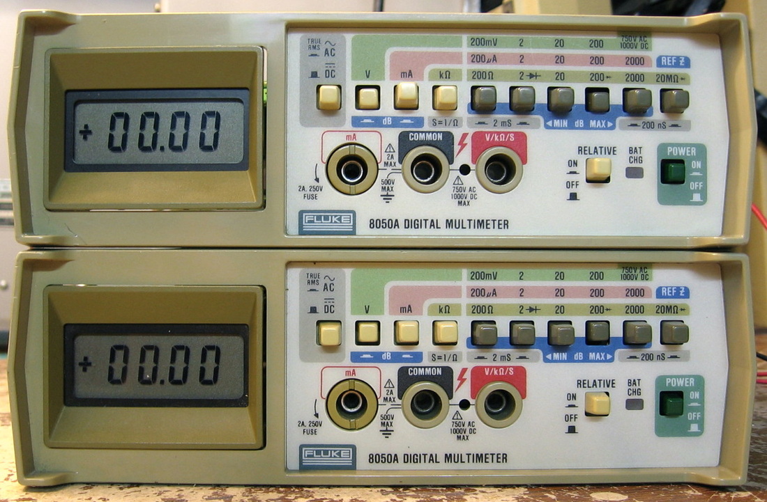
Fluke 8050A: Basic 4-1/2 digit DMM with a couple of extras, such as dB display and relative display. These units have the NiCd battery option. LCD display means I can't use it in the dark. (PDF) Grade: B-
Both of these were purchased in one buy. The 4 NiCd batteries in each were bad and these batteries are integral to the power supply (one of the regulators floats over the battery voltage). While waiting for batteries to arrive, an external P/S allowed me to verify and calibrate both units. But that's not until a lot of cleaner was sprayed into all of the pushbutton switches. The designers of DMMs like to route the input signal through multiple switches at all times - the switches all have to work flawlessly or the unit will be erratic.
Postscript: Fast forward a few years and the unit became erratic. I was convinced that there was a problem with the electronics, but it ended up being the switches, which seem to be nearing their end of life. With a lot of repeated cleaning, the unit seems OK now.
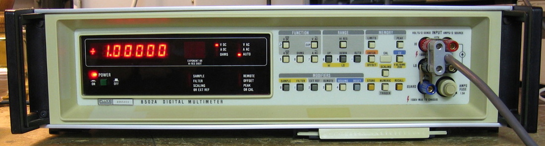
Fluke 8502A: 6-1/2 digit DMM. It really is a 5-1/2 digit unit unless one selects the high resolution mode which then adds another digit. However, the accuracy specs are not improved in high resolution mode, so what's the point? In what must have been dictated by the Fluke accountants, they decided to offer the base model with DCV only. Want ACV? That's an option. Want resistance? Option. Want current measurements? Option. Want to store calibration constants? Option. And on and on. There is a list of options printed on the back panel with an annotation for each that is installed. The eBay seller was so confused that he offered the piece as having ALL of the options, but I, of course, knew better. Having said all of this, the 8502A is very well done, has a bright clean front panel and is very accurate (0.001% best case spec). Rather than the usual dual slope integration technique used by HP and just about everyone else, Fluke has a "remainder" algorithm that acts as a successively finer recursive A/D converter. I don't know if Fluke eventually abandoned this design, but I would put the performance on par with the HP 3455A. Fully loaded, the 8502A is probably a great buy if you can get one for less than $100. Deserves an "A" grade, but I'm knocking a full point off for Fluke's ridiculous option arrangement. (PDF) Grade: B (see below for update)
OK, my unit did have an option: GPIB. However, seeing as the unit hung with no display on turn on and was totally cured by removing the GPIB board, my unit now has no options (I might eventually fix the GPIB board if I can make an extender some day). However, the cure was short lived, since the unit was unresponsive to any input voltage. The input banana jacks go to a pair of relays on the conditioner board and one of these relays was totally frozen. Drew current, but the armature didn't move. So I removed both relays, dissected and cleaned them thoroughly, and reinstalled. Works great now.
Postscript: The 8502A would command a permanent place on my stack if only it had at least the ACV and Ohms functions. There were several eBay listings for these two modules at about $50 each. But instead, I managed to buy for <$50 another whole 8502A that had these two modules. The unit was advertised as "powers up but doesn't work right." When I received the new unit, I pulled the ACV and Ohms boards out and transferred them into my existing 8502A. I also noticed that the DC input board was a newer design with latching relays, and since I was having problems with the original DC input board relays, I transferred that board into my existing 8502A also. Everything works great and I can up the grade from B to A.
Postscript^2: As a result of the Postscript above, I was left with another dysfunctional DC-only Fluke 8502A. And dysfunctional it was, giving me very strange readings and responses to the keyboard. Quite puzzling was the fact that I didn't get the usual "Error 9" message (no option installed) when I pressed the AC, Ohms or Current functions - just a lot of relay clicking and random readings. Looking through the manual, I noticed a sentence claiming that if the Calibration Enable switch was set to on, the unit disabled all error messages and gave random readings. The calibration switch is accessed through a hole in the front panel and there was a paper "Do Not Remove" sticker over the hole. Hmm, could the previous owner have been that stupid? Yup.
Postscript^3: Recently picked up the current shunt card for $40 and installed it into the first 8502A. Now I have a complete unit that does DCV, ACV, DCI, ACI and ohms. Fine and dandy.
Postscript^4: For about a year or so, the 8502A would occasionally have a blank display on startup or would delay the display until well after the initial welcoming alphanumerics. However, the display always eventually came back. The problem was traced to the U18 circuit on the display board, whose time constant is set by a 10M resistor and 1200pF cap. Replaced the chip, resistor and cap and all seems well. The resistor had morphed into 12M which I suppose didn't help things. Added note: several weeks have now passed and the 8502A has started flawlessly every time, so I'll claim victory.
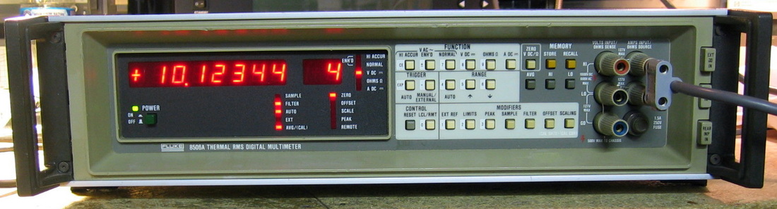
Fluke 8506A: 7-1/2 digit DMM (really 6-1/2 digits with 7-1/2 enabled in some ranges) as configured to measure DCV, ACV and ohms. From what I can ascertain, Fluke came out with a slightly better version of my 8502A, nomenclatured the 8505A. How they managed to improve the specs, while the schematics appear virtually identical, is still a mystery to me. Then Fluke came out with a whizz-bang thermal RMS converter module and replaced the AC module in the 8505A with the thermal one - they called the result the 8506A. The AC specs on the 8506A are pretty good achieving best-case accuracies of 0.012%. Similarly, the best-case (24 hour) base specs on DCV and ohms are an outstanding 0.0006% and 0.002%. But, those numbers are highly misleading, as they have to be de-rated for temperature and time since calibration, plus the usual "number of counts" slop added on. Operation of the 8506A is a not at all intuitive since there are three ACV modes plus a very annoying and confusing "zero" button on DCV and ohms. While the manual explains some of this, the real confusion comes when you try to calibrate it. One can calibrate the 8506A by turning pots or one can calibrate it through software (via stored calibration constants). What Fluke really doesn't explain is that one probably needs to do it both ways. First, the hardware calibration is what will ultimately set the linearity of the device. The software calibration can then set the overall accuracy. So, for instance, after doing the software cal at 0.19 and 1.9 volt set-points, the 8506A read 15 ppm high at 1.0 volt. Not bad, but probably can be improved. On the other hand, the ACV seemed extremely accurate at intermediate points. Finally, I've never seen a mutli-meter take so much time to do an ACV measurement. Using the enhanced-accuracy mode, it takes about 5 seconds to get a reading. Even in the normal ACV mode, it takes five or six seconds just to auto-range. Not quite sure why Fluke did this, since I have several other thermal RMS meters (including Fluke's own 8921A) that are almost instantaneous. I guess one pays for improved accuracy. All in all, a very nice meter, but it would drive me nuts to use it as a general purpose DMM. I think the 8506A will only get turned on when I need to do a "specialty" measurement. Probably deserves an A- grade, but I'm deducting points because the double-slot ACV board precludes the ability to install both the ohms and current option boards at the same time. What, you couldn't have made the chassis 2" deeper and added another slot? (PDF) Grade: B+
Postscript: I remarked in my description of the Fluke 8520A below that the meter seemed very linear throughout a DC range. And I would also expect similar behavior with the 8502A and 8506A. Initial tests with the latter two meters proved a bit disappointing, but once they were properly calibrated, things looked fine. Unlike the HP 3456A for instance, which calibrates voltages at the range boundaries, the Fluke DMMs require a lot more fiddling in order to get their recirculating-remainder A/D converter linear. All very doable, but a pain in the neck.
Advertised by the seller as 1) fully working and 2) maintained under calibration control, he was almost right, except for the fact that 1) it didn't fully work and 2) the calibration was way off. Actually, DCV and ACV fired right up, but ohms was completely whacked out giving me "Error H" on low ranges. On higher ranges, everything seemed about 1.6x too high. I did a quick check of the output voltage in ohms mode, and it was about 1.6x high (what a surprise!). The "Error H" came about because it was tripping the internal protection. Studying the schematic for a while pointed to only one possible cause - a faulty LM301 op-amp in the ohms module. Popped it out, put in an LM318 from the junkbox, and ohms was fixed. That left me with the calibration which took me several tries and several hours. I also don't like the fact that it seems like you can only calibrate it in 4-wire ohms, which I rarely use, even at low scales. I tricked it by running shorting bars between the input and sense terminals and then essentially calibrating it as a 2-wire connection. The only other annoyance is that the power transformer hums a little. I pulled out the P/S module in order to see if something could be tightened down. But I saw a whole lot of replacement electrolytics, fried traces, jumper wires, etc., that the previous owner installed. I took one look at the mess and decided not to fool around with it.
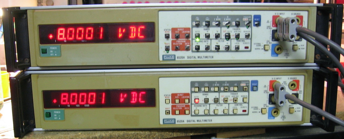
Fluke 8520A: 5-1/2 digit DMM measuring DCV, ACV, Ohms (2-wire and 4-wire) and Conductance (used as a reciprocal measurement for resistances > 10 Mohms). Basic DCV accuracy (24 hr) is about 0.003% which puts it in the class of some of HP's DMMs, notably the HP 3455A. Mine has Option 10 which adds several math functions to the standard list. Noteworthy is one of these functions which directs the 8520A to run in a burst mode which then mathematically can calculate the ACV of sine waves with frequencies as low as 0.5 Hz. Certainly one of Fluke's better efforts, after calibrating it at the endpoint of the ranges, it was extremely accurate throughout the range. Several of the non-HP DMMs I have seem to be non-linear throughout the range. I would have graded this piece higher, but the front panel mechanics aren't very good. (PDF) Grade: B+
Postscript: A second unit was procured recently and both are shown in the photo. See below for repair notes on the second unit.
This one just about killed me. No functional description from the seller other than a power-on picture, but when received, the P/S supplying the digital side of the unit was at 0 V. This was traced to a small daughterboard in an edge connector which had slipped laterally a bit. Rather than key the connector, Fluke simply strapped a tie-wrap around it and hoped that it aligned with the board slot. The tie-wrap slipped and so did the board. Dumb. But that was the least of my problems. The thing fired up but was missing some segments of the last four 14-character alphanumeric LEDs. Moreover, the front panel keys were in very poor shape with some cracked, some dysfunctional, some loose, etc. Fluke's keys are hollow and several have a clear cap so that a tiny LED can be jammed in there. Good luck finding those. I did find the dual 14 segment LEDs from someone in Poland and a bunch of tactile switches from England. The tactile switches were vanilla, so I decided to drill small cutouts for LEDs underneath where the switches would pop through. While I was waiting for delivery, various supposedly unlit segments of the numerical displays started to light dimly. And then all the button LEDs lit dimly. I must have spent 10 hours trying to track down the problem and never got to the bottom of it. Finally, as I was trying various pulldown resistors, I guess I shorted something because the display turned off, the unit groaned, and smoke poured out the back of the display board (all the components are on the front side!). It turns out I had only destroyed a Zener and a 1N4148, so I got the thing back to where it had dimly lit segments and LEDs. At the suggestion of this web page's technical adviser I installed small current shunting resistors across the front panel LEDs to at least turn those off. There wasn't much I could do with the numeric LEDs because the displays are highly multiplexed and shunting current from one numeric LED segment would just cause another to turn on. So the bottom line is that all the tactile switches were installed and the 8520A works very nicely. If you turn off the surrounding lights and look carefully, you can see some dimly lit segments that are supposed to be dark. Whether this current leakage is from the numeric LEDs themselves or some problem I was never able to track down, remains a mystery.
Postscript: When last we left our heroes, the decimal point and "C" segment of all the numeric digits were dimly lit, as were all six of the front panel LEDs. Putting small current shunting resistors across the six panel LEDs at least turned those off. On a hunch that the numeric LEDs were at the root of the problem, I found two 2-digit and one 1-1/2 digit seven segment common cathode numeric LEDs on eBay. The 1-1/2 digit LED was the first to arrive and was exchanged with the one in the 8520A. Upon power up, the decimal point and "C" segments were dark and I was almost ready to claim success, but noticed now that the "1" in the overflow digit was dimly lit. I unsoldered two of the six current shunts on the front panel LEDs and now only the lower half of the "1" was lit. So I took all the shunts out and now there are no dimly lit numeric segments or front panel LEDs. Finally. I suppose when the two 2-digit LEDs come, I'll put them in because the new ones are red and the old ones are orange. I did do a post-mortem on the numeric LED I pulled out. Sure enough, the decimal point and "C" segments showed 2-3 ma of reverse leakage. But I cannot quite explain the connection to the six front panel LEDs which are tied to six of the segments, not just those two. I guess the moral to the story is: those pesky electrons will always find a way to get from one place to another.
Postscript (2nd unit): While my original front panel fix was adequate, it was far from desirable since the replacement tactile switches tended to push in beneath the front panel. The proper solution would have been to buy another 8520A and use its front panel. And so I was fortunate enough to find two broken 8520As listed on eBay with perfectly good front panels. My buddy and I split the purchase - a whopping $20 for both! Upon receipt, I switched front panels with my good unit. But then I still had a broken 8520A remaining and I can't have that, can I? The tag on this 2nd piece said "unit will not zero on any range or function." Well, I suppose that was true if you could actually power the thing on without blowing the main fuse. Bottom line: one electrolytic, two tantalums, a 74LS03 and four discrete transistors were blown. Took me a few hours to track everything down, but at least it's fixed.
Postscript^2 (2nd unit): To make matters even more confusing, I picked up a new front panel board for ten bucks which replaced the one I had reworked for the first unit and then transferred to the second unit. Now I have two pristine 8520As that can sit on the shelf unused.
Postscript^3: I don't remember which of my units is which, but one of them recently had a short on the 15V rail which was easily traced to a shorted tantalum in the AC measurement circuitry. If I recall, the other unit had the same defect at one point.
Postscript^4: Many months later, I found yet another shorted tantalum on one of my 8520As. There are two tantalums on the +/-15V rails in the AC measuring circuitry. These 10 uF, 20 V caps are pretty much guaranteed to fail eventually if my experience is correct. Preemptively replace them if you have a working 8520A.
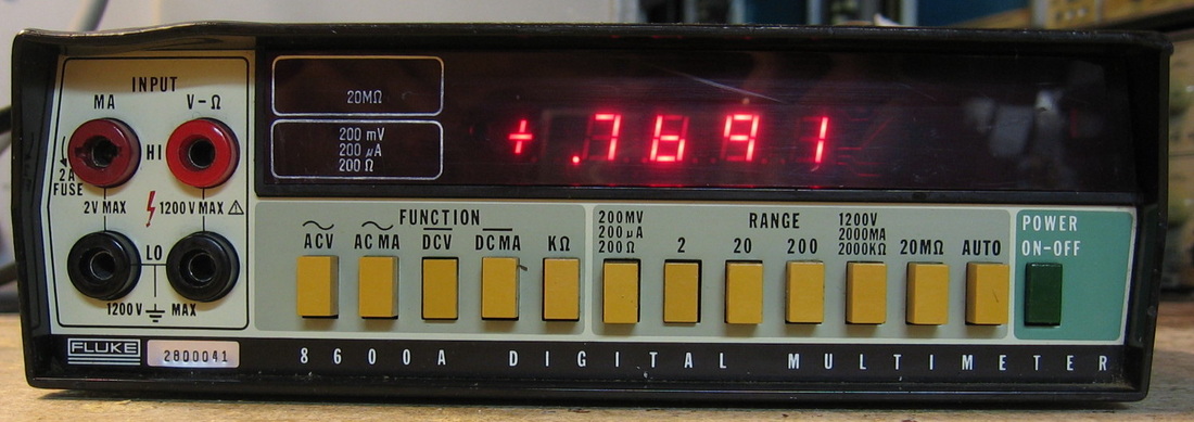
Fluke 8600A: 4-1/2 digit DMM. At least this model does volts, current and ohms and has auto-ranging. It would be a pretty good offering from Fluke if only it had decent accuracy. The specs are laughable: 0.01% for DCV and 0.1% (or worse) for all other measurements. The lack of fidelity is also apparent when you go to the calibrate the unit. There are only a few adjustments and you just know that the thing can't be fine tuned very much. A very low end model that was hardly worthy of the $10 I spent for it. (PDF) Grade: C
This was advertised as "erratic on ACV" and it certainly was. After a lot of substituting parts, the problem was traced to a current limiting diode on the ACV board. I thought I tested it right at the start, but I guess I was fooled by my in-circuit test and should have pulled the part. The diode is supposed to source 5 ma. Since these things are essentially a JFET with the gate tied to the source, I pulled a JFET out of my junkbox and managed to get about 1.5 ma out of it. So I installed that and the thing gave accurate ACV readings. However, it wouldn't auto-range to the next higher range because the current wasn't enough. So I installed a second JFET in parallel with the first. Nice of Fluke to even give me a spare set of holes on the board right next to the original part. Everything works now to "spec," if you can call it that.
This was advertised as "erratic on ACV" and it certainly was. After a lot of substituting parts, the problem was traced to a current limiting diode on the ACV board. I thought I tested it right at the start, but I guess I was fooled by my in-circuit test and should have pulled the part. The diode is supposed to source 5 ma. Since these things are essentially a JFET with the gate tied to the source, I pulled a JFET out of my junkbox and managed to get about 1.5 ma out of it. So I installed that and the thing gave accurate ACV readings. However, it wouldn't auto-range to the next higher range because the current wasn't enough. So I installed a second JFET in parallel with the first. Nice of Fluke to even give me a spare set of holes on the board right next to the original part. Everything works now to "spec," if you can call it that.
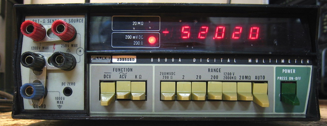
Fluke 8800A: Over the years, Fluke has made dozens and dozens and dozens of DMM models. This one happens to be a 5-1/2 digit version with no amps capability, but with 4-wire resistance measurements. Oh, wait - Fluke just came out with another model. (PDF) Grade: B-
Unlike the Fluke 8050As, this one really had a power supply problem; none of the three intertwined supply voltages were correct. The supplies have heat-sinked transistors and all but one of them was nice and warm. The other one was ice cold. Put in a new one and that's the end of that problem. No need for a schematic, no need for a voltmeter, no need for anything except my finger. Now that's how you fix test equipment. The meter also suffered from dirty switches and needed a spritz or two of tuner cleaner.
Postscript: The unit developed a strange fault where it would not auto-range from the 20 to the 200 VDC range if the voltage was increased rapidly (it would auto-range otherwise). It also wouldn't indicate an over-range on the 20 volt manual scale if initially presented with a voltage > 21V. Moreover, everything worked fine when negative voltages were input. After about 8 hours of banging my head against the wall, I found the problem. The input signal goes through some op-amps whose supply rails obviously have to be outside the range of the input. The op-amps are supplied by two transistor current sources from +/-35V feeding two zeners. The positive current source PNP transistor developed a defect in which the collector voltage dropped down below the op-amp supply voltage constraint. Hence a 21V signal would only produce this lower voltage out of the op-amp and would never be detected by the unit as over-ranged. My solid state physicist colleagues at work say that the emitter punches through some of the base region. the transistor then conducts virtually all of its current from E-B rather than E-C, and the collector voltage drops too far. But what do they know? I bet they wouldn't know a logic probe if I poked it in their ass.
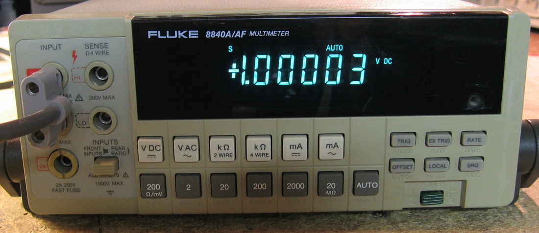
Fluke 8840A: 5-1/2 digit DMM with VDC, VAC, ohms and current. This model is a little more accurate than the usual Fluke benchtop models and enjoys a fairly respectable reputation. Best case (24 hour) accuracies are 0.002% (DC), 0.07% (AC), 0.0028% (ohms) and 0.04% (current). The auto-ranging is particularly quick on this model. The features are minimal, but there is the convenient reading-rate selection and an offset null. (PDF) Grade: A-
For forty bucks, I got two of these: an 8840A and an 8840A/AF. The AF model has DC ratio and some extra filtering on the AC line. But whoever had these last attempted to mix and match boards, so I'm not even sure which is which anymore. Nonetheless, both were offered as non-working. The first one powered up fine, but the display was intermittent and the ACV readings were incorrect. The intermittent display was traced to cold solder joints on the main transformer (a common problem according to the Fluke newsgroups). The ACV problem was traced to a faulty NE5532 op-amp on the AC board. The second unit rattled when shaken, and that was being caused by loose wires that the previous owner had simply thrown back in the unit after he unsoldered them from the AC input socket. Moreover, all the wires to the front panel were disconnected. So it was clear that attempts were made to substitute major components in the second unit. After I hooked everything back up, the second unit powered up, relays clicked, and the display was dead. After I wasted an hour on digital/display debug, I pulled off the plastic display cover only to see the very nice Vacuum Fluorescent Display had two enormous cracks in it. So much for the vacuum, so much for the display, and so much for the unit. Oh well, at least I have some spares for the working unit.
Postscript: I re-mixed and re-matched the boards and put the working unit to the full "AF" version. It has slightly better specs.
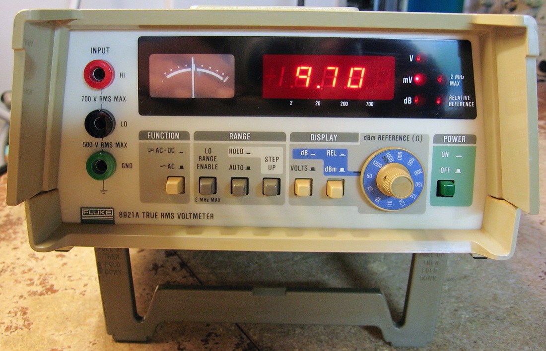
Fluke 8921A: AC RMS Voltmeter, 10 Hz to 20 MHz, 180 uV to 700 V. 3-1/2 digits in volts mode, 4-1/2 digits in dBm mode (with selectable reference impedance). Has an "uncalibrated" analog meter for use when peaking a signal. The accuracy is specified as a function of frequency and voltage and runs from 0.5% to 5%. Simple and easy to use. (PDF) Grade: A-
This was advertised by the seller as "powers on but malfunctions." No further explanation or details. So I took a chance that it was fixable. The 8921A uses a thermal sensor made up of a pair of transistors forming a differential amplifier and two resistors that heat up. It is in a sealed package and is unobtainable. The calculations and display are done by a Fluke custom IC. Other than that, it should be fixable. But, alas, when I received the unit, I couldn't find anything malfunctioning. Plus, it calibrated nicely which usually proves everything works. My only complaint was that the analog meter was a bit low. It only went up about 3/4 of the way for a full-scale input. So I simply paralleled a resistor across the meter circuit to boost the current to the meter a bit.
This was advertised by the seller as "powers on but malfunctions." No further explanation or details. So I took a chance that it was fixable. The 8921A uses a thermal sensor made up of a pair of transistors forming a differential amplifier and two resistors that heat up. It is in a sealed package and is unobtainable. The calculations and display are done by a Fluke custom IC. Other than that, it should be fixable. But, alas, when I received the unit, I couldn't find anything malfunctioning. Plus, it calibrated nicely which usually proves everything works. My only complaint was that the analog meter was a bit low. It only went up about 3/4 of the way for a full-scale input. So I simply paralleled a resistor across the meter circuit to boost the current to the meter a bit.
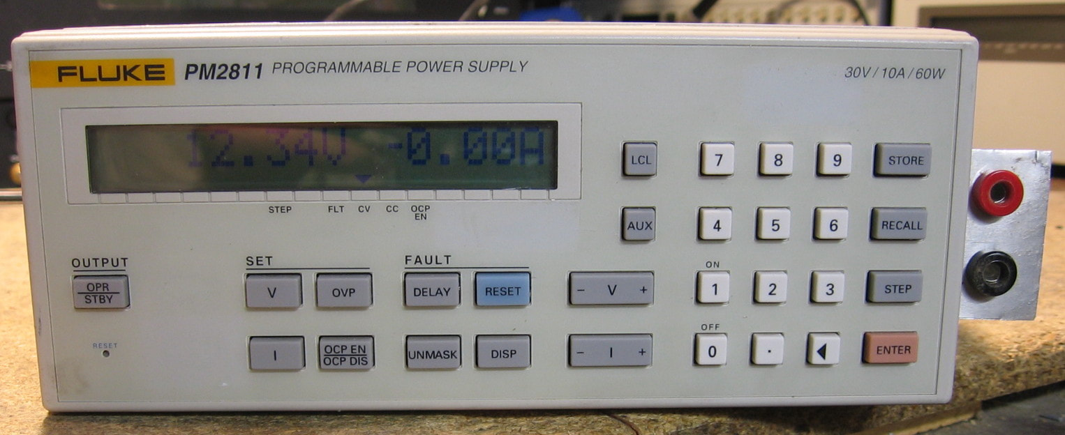
Fluke/Phillips PM2811: 60 watt switching power supply. Phillips also made a 2812, 2813, 2831 and 2832 having different ratings and/or multiple outputs. Mine will do up to 30 volts and 10 amps in whatever combination keeps V*A<60. The accuracy and stability specs are as good as any modern power supply, but being a switcher, the output noise is a pretty hefty 3 mVRMS. Phillips really engineered these power supplies very well; the build quality is first rate and there are some extra goodies lurking around like the ability to store a bunch of settings in memory and then step through them with one button press. I wish their service manual was complete, however. It only describes the uP and associated digital circuitry; the actual power module is not described (they say to send it back for service). And once again, why did they put the power switch on the back panel? Probably because it is integral to the Schaffner line filter (which will most likely blow up soon enough!). (PDF) Grade: A-
The seller said that the unit displayed a "FAILED" message on the screen. But his pictures showed the sense lines were not connected. A simple fix for anybody who knows anything. But after I bought it, while I was waiting for delivery, I perused the service manual where it said that if the sense lines were not connected externally, there were internal resistors that made the connection. So much for my theory then. But it turned out that as soon as I did connect the sense lines, the faults disappeared and the unit performed perfectly. Finally, I mounted a small piece of metal with two banana jacks to the side panel and ran wires back to the output terminal on the rear panel.
The seller said that the unit displayed a "FAILED" message on the screen. But his pictures showed the sense lines were not connected. A simple fix for anybody who knows anything. But after I bought it, while I was waiting for delivery, I perused the service manual where it said that if the sense lines were not connected externally, there were internal resistors that made the connection. So much for my theory then. But it turned out that as soon as I did connect the sense lines, the faults disappeared and the unit performed perfectly. Finally, I mounted a small piece of metal with two banana jacks to the side panel and ran wires back to the output terminal on the rear panel.
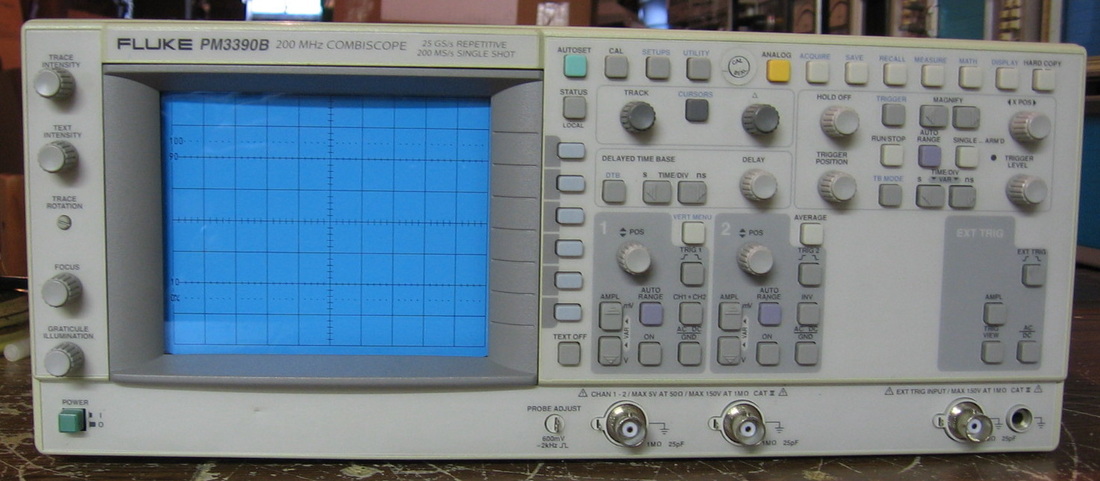
Fluke/Phillips PM3390B: 200 MHz Combiscope operates as both an analog scope and as a digital storage scope with a push of a button. In the digital mode, will do all kinds of measurements. Have one of the matching Phillips 10:1 probes. The only thing wrong when I received it was a banged-up case. Good thing it didn't really need repair, because it is all VLSI gate arrays. This is a wonderful scope - probably the best overall scope I have. There are times you need analog and times you need digital capability, plain and simple. (PDF) Grade: A
The repair of the case was more than simply straightening it out. I had to pop all the rivets out of the case just to get the case free of the scope. It was great fun banging on it with a hammer while the scope was inside! After I freed the case, I banged it into shape, repainted it and then put machine screws where the rivets were in order to close the case back up. The scope slid back into the case with a little persuasion. I hope I never have to get it out again.
Postscript: Haven't had too much desire to use this scope given some of my other ones, but recently I fired it up and it seemed a bit off in the calibration. I checked the two AA memory-backup batteries (in a little compartment on the back panel) and was greeted with gobs of dried up battery acid. Cleaned it all up, installed fresh batteries, ran through the calibration, and all is well.
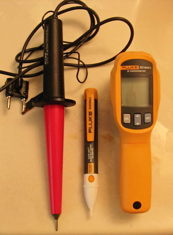
Fluke Grab-bag: Here are a few miscellaneous Fluke objects. Some were gifts, some were freebies with other purchases and some were bought. You can try and figure out which. Shown are 1) Fluke 80K-6 high voltage (6000 V) probe, 2) Fluke 2AC "VoltAlert" AC voltage probe and 3) Fluke 62MAX IR thermometer. All of them work exactly as they should and have their uses. But I miss the patented Fluke yellow color on the HV probe! (OM/PDF) Grade: A

Frequency Devices 902LPF1: Basic 8-pole Bessel low pass filter to 30 kHz. Has the ability to subtract two channels and to add 10 or 20 dB amplification. Also has a DC offset adjustment. Six nice sealed black boxes inside, surrounded by a few op-amps, a ton of resistors in the feedback network and 16 wafer's worth of switching. Not much more to say. (---) Grade: A-
Pretty well shot when I received it, but it just needed a thorough soaking in tuner cleaner. Not a single pot to adjust inside (boo).
Postscript: The soaking in tuner cleaner didn't last. What a surprise. Each front panel knob controls four wafers which are each sealed in plastic. I meticulously desoldered each wafer (12 pins per wafer) and removed them. Fortunately, they were made for disassembly and simply snap open. My tuner cleaner mixed with the old grease (or whatever was originally in them) and turned the whole inside to a gooey mess. I used my favorite solvent, carb/choke cleaner, and cleaned everything up. Reinstalled all the wafers and it is much better now.
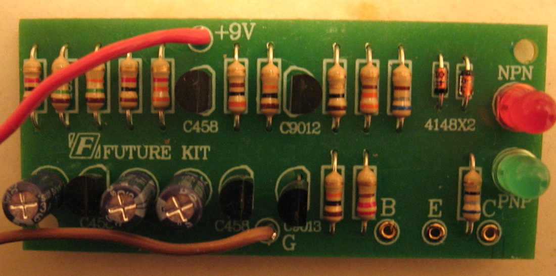
Futurekit FK-907: Super duper transistor checker. Just awkwardly bend your transistor leads, which nowadays are almost always E-B-C, into a B-E-C configuration and put them in the holes. Attach a 9V supply and watch the NPN or PNP LED blink. The Chinese should get the Nobel prize for this design. Basically a square wave is generated at some fixed slow frequency which alternately blinks the two LEDs. The test transistor, if good, shorts out one of the two LEDs leaving the correct one still blinking. (PDF) Grade: D
Many of the pieces of test equipment I've bought have had some defective parts. Occasionally, a part or two might be actually missing. But on this piece, the previous owner removed every single part from the board, carefully extended all the component leads to full length and neatly packaged them in a plastic bag. He even desoldered the PC board for me. I managed to restore the piece to its original condition.
Many of the pieces of test equipment I've bought have had some defective parts. Occasionally, a part or two might be actually missing. But on this piece, the previous owner removed every single part from the board, carefully extended all the component leads to full length and neatly packaged them in a plastic bag. He even desoldered the PC board for me. I managed to restore the piece to its original condition.
G : General Electric, Genrad, Gigatronics, Global Specialties, Guildline
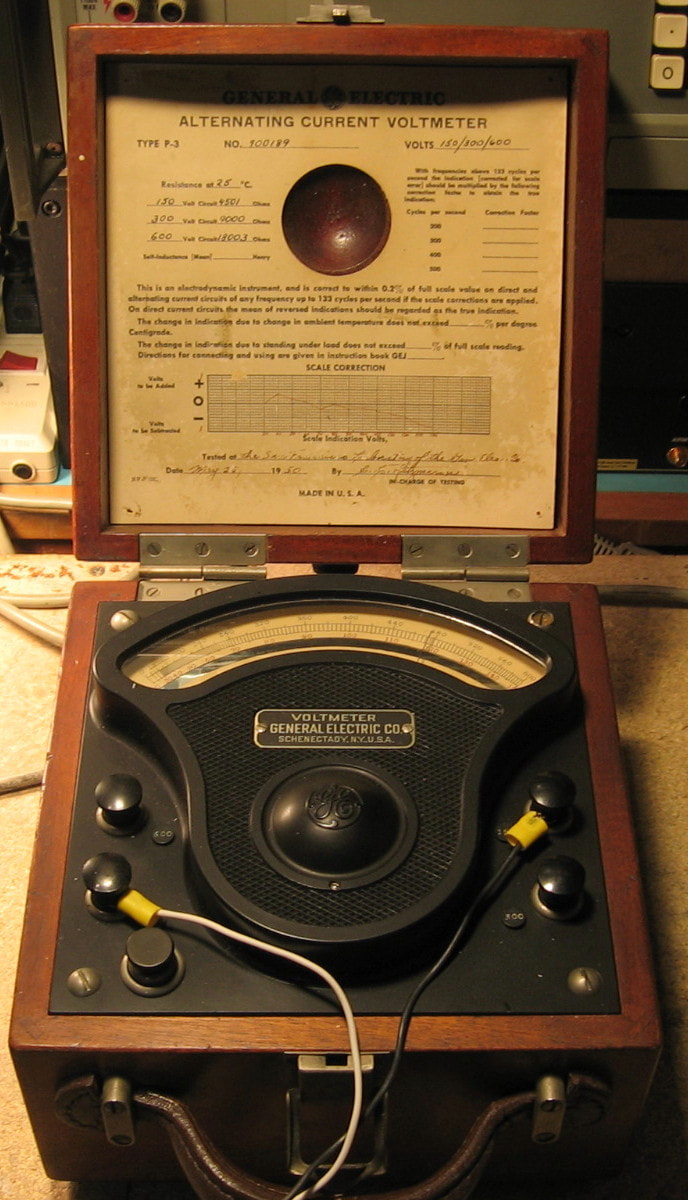
General Electric P-3: Sent to me by an anonymous donor, this is a vintage AC voltmeter built in 1950 (most likely in the West Lynn, MA plant). It has three full-scale ranges, 150, 300 and 600 VAC and is responsive from DC to 133 Hz (a DC measurement is possible by taking the mean of the two readings with the leads reversed). GE made a number of meters under the P-3 nomenclature, including voltmeters, ammeters, wattmeters, power factor meters, and probably a whole lot of custom versions; they were made at least from the early 1910s through the 1950s. The AC voltmeter is an iron-vane type which directly measures RMS (without the customary rectifier found in VOMs) and the accuracy is outstanding: 0.2% of full-scale. That accuracy is achieved courtesy of a calibration correction chart affixed to the wooden lid. You would be hard pressed to find any modern piece of test equipment with an analog meter that advertises a 0.2% spec. About the best I've seen is 1.0% and most are >2.0%. The insides consist of 1) the massive meter movement, 2) a simple shorting bar acting as an on/off switch, and 3) a set of 10 wirewound resistors (each about 5" long) that make up the three range resistors. The wooden box has ventilation holes on the back for these resistors, because they will warm up at full-scale voltages. The P-3 is the oldest piece in my collection (by far), even older than I am, and represents an era where things were built to last. How can I give it any grade except an A. (---) Grade: A
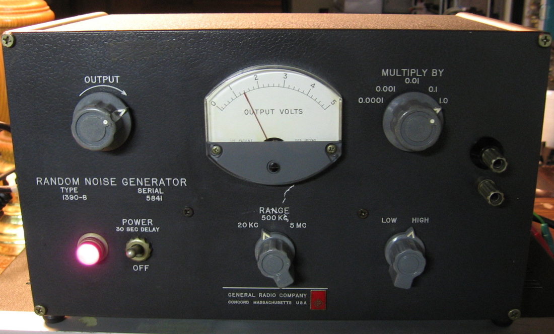
Genrad 1390B: The Genrad 1390B is a white Gaussian noise generator with adjustable amplitude and selectable noise bandwidths to 5 MHz. It uses a 6D4 tube in a magnet for noise generation and a couple of vacuum tube amplifiers. It is not particularly white or Gaussian except on the 20 kHz range. Tried several different 6D4s to no avail. I guess this is what they used in the sixties. A good noise diode would run rings around this. (PDF) Grade: C+
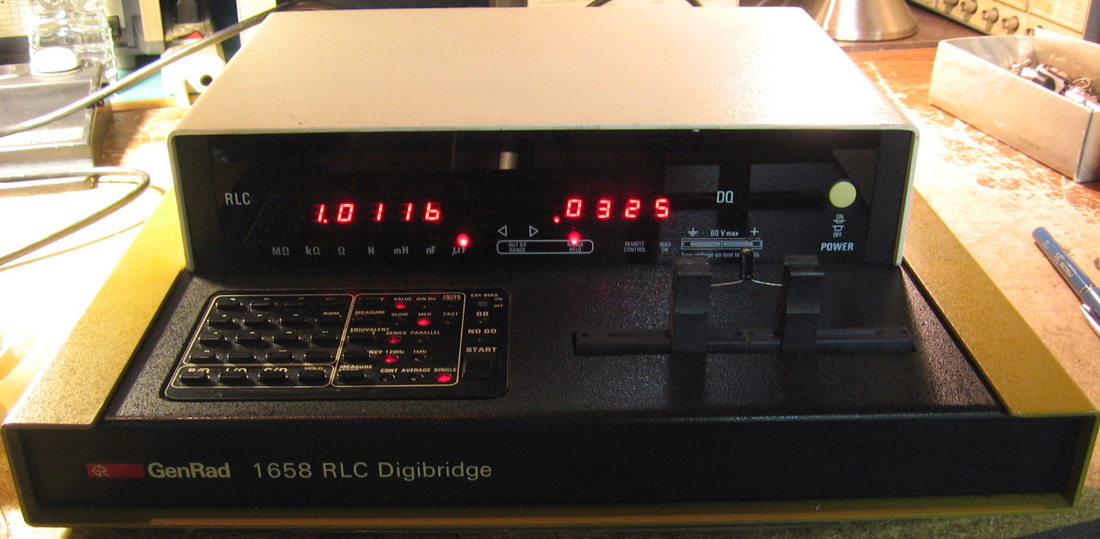
Genrad 1658: LCR meter, one of the "Digibridge" series that is in some form still being made today by IET Labs. A curious circuit using a complex voltage ratio measurement through the DUT and one of three precision internal resistors (depending upon range). This technique requires a precision frequency and phase sources and so Genrad generates things digitally through a ROM look-up table. Because of this scheme, there are absolutely NO internal adjustments. Not even the power supply has a pot. What comes from the factory is calibrated for life. Genrad claims a basic accuracy of 0.1%, which beats my HP 4262A and is on par with my ESI SPS5110 unit. In fact, it is a good complement to the ESI unit which has only 1 kHz and 10 kHz measurement frequencies; the Genrad 1658 has 120 Hz and 1 kHz. But unlike the 1658's three precision resistors, the SPS5110 uses 70 of them! The 1658 was clearly geared towards incoming inspection, since it allows the user to set up 10 range "bins" and will tell you which bin the part belongs in. Among my HP 4262A, ESI SPS5110, Genrad 1685 and Genrad 1658, the 1658 is both the easiest to use and the one with the least amount of features - I guess that goes hand-in-hand. Build quality is OK, certainly not as good as HP. (PDF) Grade: B+
Postscript: Gee, maybe I should have read the op-manual! It sort of bothered me that the GR1658 won't measure the ESR of a capacitor like my HP 4262A. The 1658 has three main measurement buttons: R/Q, L/Q and C/D. Insert a capacitor, press the C/D button and get a readout of capacitance and dissipation. I thought it ended there. But no, press the R/Q button with the capacitor in place and you get ESR and Q=1/D. D'oh. Anyway, I'm bumping the grade up to an A since the 1658 is now as versatile as the HP 4262A, more accurate and was about half the original MSRP.
For fifty bucks, I was willing to take a chance on a "powers up but no display" piece. That's pretty much how it arrived, but in addition to no display, the unit was completely locked up and unresponsive to any keypad presses. I've seen behavior like that, particularly with my HP 3455A DMM where the problem was that the analog measurement never successfully finishes and so the processor simply sits there in a loop waiting for it and only it. After the usual P/S checks, I started probing around. Many hours later I had isolated things to the control surrounding the integrator-based measurement circuit. Basically, the 6502 uP issues commands through an MC6820 Peripheral Interface Adaptor which then goes through six buffers comprised of two 74C907 hex-buffers (why they used two hex chips instead of one, who knows) which controls four analog switches (CD4016). These switches control the integration, zeroing, switching in of reference voltages, etc. So it's difficult to determine whether the integrator, the processor or the buffers/switches aren't working when the whole thing simply locks up. Anyway, because all of the ICs were socketed, I was able to switch the two 74C907s and suddenly the thing sprang to life - for about one minute, then locked up. I put the two chips on a breadboard and did a quick analysis. Buffer #3 on one of the chips was faulty and since these things are FET-based, I think the reason the unit worked for a minute had more to do with residual capacitance than heat. Since I didn't have a spare 74C907, I simply lifted the input and output pins for buffer #3 and jumpered the IC socket pins over to one of the three remaining buffers that wasn't being used (nice of Genrad not to use a single hex chip to do all six buffers, wasn't it?). Perfecto. I suppose I should order a replacement chip and do it right, though.
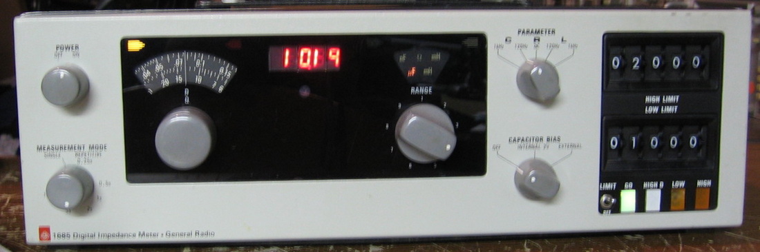
Genrad 1685: General Radio digital impedance bridge. R-L-C at 120 and 1000 Hz. This one also has the limit switches and automatic pass/fail functions. Don't have enough standards to properly align the thing, but it generally is very close to the HP 4262A. The 1685 is a semi-automatic bridge. You put a component into the Kelvin test fixture and the digital readout tells you the value - provided that you've set the range switch correctly (it tells you which way to turn it if not). You then turn the dial to measure the D or Q. (OM) Grade: A-
This one was giving erroneous readings on the digital display. At first I thought it was a problem on the digital board. But many pointless hours later, I discovered two faulty LM201 op-amps on the analog measurement board.
This one was giving erroneous readings on the digital display. At first I thought it was a problem on the digital board. But many pointless hours later, I discovered two faulty LM201 op-amps on the analog measurement board.
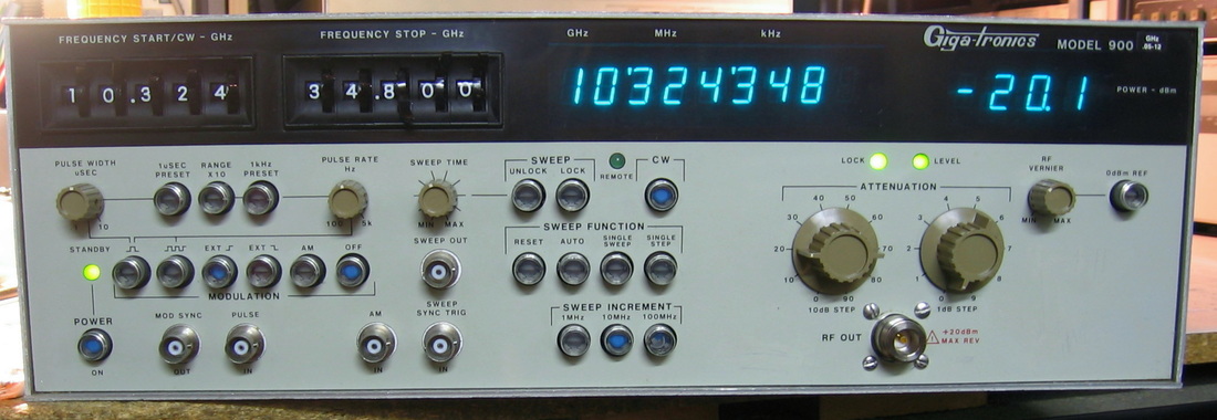
Gigatronics 900: The 900 series microwave signal generators cover a variety of frequency ranges to 26 GHz. Mine covers 50 MHz to 12 GHz and also has the 1 kHz frequency resolution option. The amplitude spec is +5 to -99 dBm, with +/-1 dB accuracy (although mine falls a bit short of the max power as described in the repair notes). It can function as a CW generator or as a sweeper, with various rates and frequency steps. The 900 also has a built-in pulse modulator and will do AM with an external input signal. The pulse modulator is very convenient because the <25 nsec rise times coupled with pulse repetition frequencies from about 100 Hz to 50 kHz means that I can take out an entire HF ham band if I hook this puppy up to my outside antenna (just kidding!). This signal generator uses what Gigatronics calls a two-step indirect frequency synthesis. There are 3 YIGs in the unit: 1) 2 to 8 GHZ reference, 2) 2 to 8 GHz output and 3) 8 to 12 GHz output. The reference YIG is locked to the 100 MHz master oscillator (depending upon user selected frequency) and then the proper output YIG is locked to that. The phase noise of the 100 MHz oscillator is multiplied only up to the reference YIG frequency; it does not propagate through the output YIGs. The way they get less than 2 GHz is by mixing and downconverting the 2 - 8 and 8 - 12 GHz YIGs. All very clever and, as you would imagine, a nightmare of complexity. Besides the two dozen circuit boards inside, there are over a dozen "black boxes", some made by well-known vendors such as Mini-Circuits, and some homespun by Gigatronics. And, of course, semi-rigid coax all over the place. One thing nice about a YIG-based generator is that the harmonics (and spurs) are -60 dBc. Most of my synthesizer-type signals generators can't get anywhere near that (typically -40 to -50 dBc). And hook it up to the HP 53310A modulation analyzer and you will get a nice Gaussian histogram of the frequency variation about the carrier. With a synthesizer, the histogram shape is slightly skewed. All in all, a very nice piece. My only gripe is the CHEAP front panel which Gigatronics made out of plastic (feels more like vinyl) which easily pulls away from its thin metal backing. Really? For a piece that had to cost at least ten grand when new, you couldn't have given us a proper painted metal front panel? Grade: A- (OM)
I spent $200 (a lot) on eBay from a seller who said the level light does not come on below 8 GHz. The level light indicates that the desired amplitude can adequately be supplied by the circuitry. Upon receipt, when set to 0 dBm power, the spectrum analyzer read -36 dBm for signals below 2 GHz and less than -60 dBm for signals between 2 and 8 GHz. I don't have a spectrum analyzer that can see the 8 - 12 GHz band, but my EIP microwave counter seemed to indicate adequate power was being generated. Tracing the various microwave paths, I determined that the 2 - 8 GHz "coupler/modulator" was faulty. This was one of the parts built by Gigatronics, and I was lucky to find one from a Chinese seller for $25. After installation, the unit sprang to life and high level signals were now seen from 50 MHz upwards. However, from about 2 GHz to 6 GHz, the unit can only make about -2 dBm on average (anywhere from about -6 to +4 dBm through the range). Outside of this frequency range, the maximum levels are from about 1 dBm to 12 dBm. I checked the output of the 2 - 8 GHz YIG and it was only about 5 dBm, so there was never going to be any way to achieve the 5 dBm output spec anyway due to the various losses through the microwave couplers, splitters, etc. Whether the YIG was damaged by feeding it into a faulty coupler/modulator before I got it, who knows. I guess I will have to live with it and I suppose I could always add a cheap Mini-Circuits broadband amplifier on the output if I really needed some oomph. At least I don't have to live with a rear-panel output SMA jack - I installed an N-connector on the front panel and re-routed the internal piping.
Postscript: I simply couldn't live with the 2 - 8 GHz band not meeting the amplitude spec. Plus, when cold, the output sometimes only got to about -14 dBm in the lower regions of the band. So I bought a replacement Avantek YIG from a seller in Australia and installed it. It had a 22 ohm resistor to the FM- coil unlike the YIG that was in there. But the schematic shows the resistor, so I left it in. Now I'm getting > 5 dBm across the 2 - 8 GHz band like I'm supposed to. In fact, across 100 MHz to 12 GHz, the average power is 10.0 dBm, the max power is 13.8 dBm at 700 MHz, and the min power is 5.7 dBm at 6.8 GHz.
Postscript^2: One day, the leveling circuit malfunctioned and I was getting >10 dBm output regardless of how I set the fine attenuator (1 dB) switch, the amplitude vernier knob, or the AM modulation. The leveling circuit is one enormous feedback loop where these settings and the detector output are all summed at the (negative) input of an op-amp. Signals are switched around using an IC5010 CMOS switch and I was convinced that it was the culprit. However, a new one not only did not fix the problem, all my outputs were know down at <-50 dBm. Careful checking showed an open connection at one of the solder points of a socket I put in for the new IC5010, and once that was fixed, I was back where I started from - namely >10 dBm output and no response from the controls. To make about a six hour story short, the detector that monitors the output goes through an amplifier board and a log-amplifier board before going back to the main summing junction. An ordinary 25K resistor in the feedback path of one of the op-amps on the log-amplifier board opened up. The result was that the log-amplifier output dominated the main summation junction and rendered all the other summands useless. Once the resistor was replaced, all was good.
Postscript^3: The unit is misbehaving slightly now. Everything seems to be fine below 8 GHz. But above 8 GHz, the amplitude leveling does not work quite right. I spent a morning trying to figure it out, but got nowhere fast, especially since all the circuitry is pretty much the same whether one is below or above 8 GHz. It isn't that you can't adjust the amplitude to whatever you want. It is that over 8 GHz, you have to turn on the vernier control and manually adjust that and the 1 dB step dial on the front panel - you can't use the "0 dB" reference button. So the unit is perfectly usable, just annoying. I'll keep working on it some day...
Postscript^4: In retrospect, the amplitude levelling might not be fixable I can adjust things correctly in the 2-8 GHz band, but then the 8-12 GHz band is wacky and vice versa. The service manual states that there is a ROM that has correction values stored for the amplitude levels and not to exchange or replace the ROM. Now since I have replaced some of the microwave components in early repairs, it may be that these stored amplitude values are incorrect for the new hardware. In that case, there is nothing further that can be done. It's not like I am going to send the unit back to Gigatronics for repair. My guess is that even if I did, they wouldn't know what to do with such an old piece of gear.
Postscript^5: I put a 7 dB attenuator inline with the 8-12 GHz signal generation to try and coerce the unit to level the amplitude. Seems to be a lot better, although I obviously can't get 10 dBm out of it anymore. Still, there are occasional amplitude settings on the 1 dB/div knob that it doesn't like. It is frequency dependent and my guess is that there is probably some degradation in either the power detector or the amplitude/modulator units. I will have to live with it.
Postscript^6: Forget Postscript^3, Postscript^4 and Postscript^5. I spent two weeks going through every inch of the digital circuitry and finally came to the conclusion that the microwave attenuator/modulator block was faulty. The schematic shows this part as M163, but my unit's module is marked M184. Luckily, I found a seller on eBay that had both of them for about $20 each, so I bought both. When I installed the M184, the Gigatronics 900 worked perfectly and the amplitude leveling problems are now gone.
Postscript^7: Well, fast forward a year or so and the unit is behaving just like it did when I first got it, namely amplitudes at frequencies lower then 8 GHz were way low (30 to 60 dB). So it looks like my replacement M162 module died (again). I obtained one from an eBay seller, spent two hours tearing the signal generator apart, and when I installed the new module, same thing - no good. I'm done trying to maintain this beast, so what I did was take tee off of one of the outputs of the M162 that was still OK (the one going to the mixer switch) and run that to the output switch (where the usual M162 output would have gone). That seems to give me good amplitudes and doesn't seem to destroy the frequency PLL circuitry. It does cost me fine amplitude control (I can only use the 10 dB step attenuator) and modulation capability. I can live with that and besides, at frequencies greater than 8 GHz, the piece works fine.
Gigatronics Bonus Rant: I'm sure Gigatronics made some nice stuff, but I'm getting pretty fed up with the 900 microwave signal generator. First, the M162 2-8 GHz coupler/modulator died. Then the 2-8 GHz YIG oscillator died. Then the M163 8-12 GHz coupler died. Then the replacement M162 2-8 GHz coupler/modulator also died. Then the replacement for the replacement M162 was dead on arrival. That's five defective microwave assemblies that have died. Maybe I am just unlucky, but that is absolutely unforgivable.
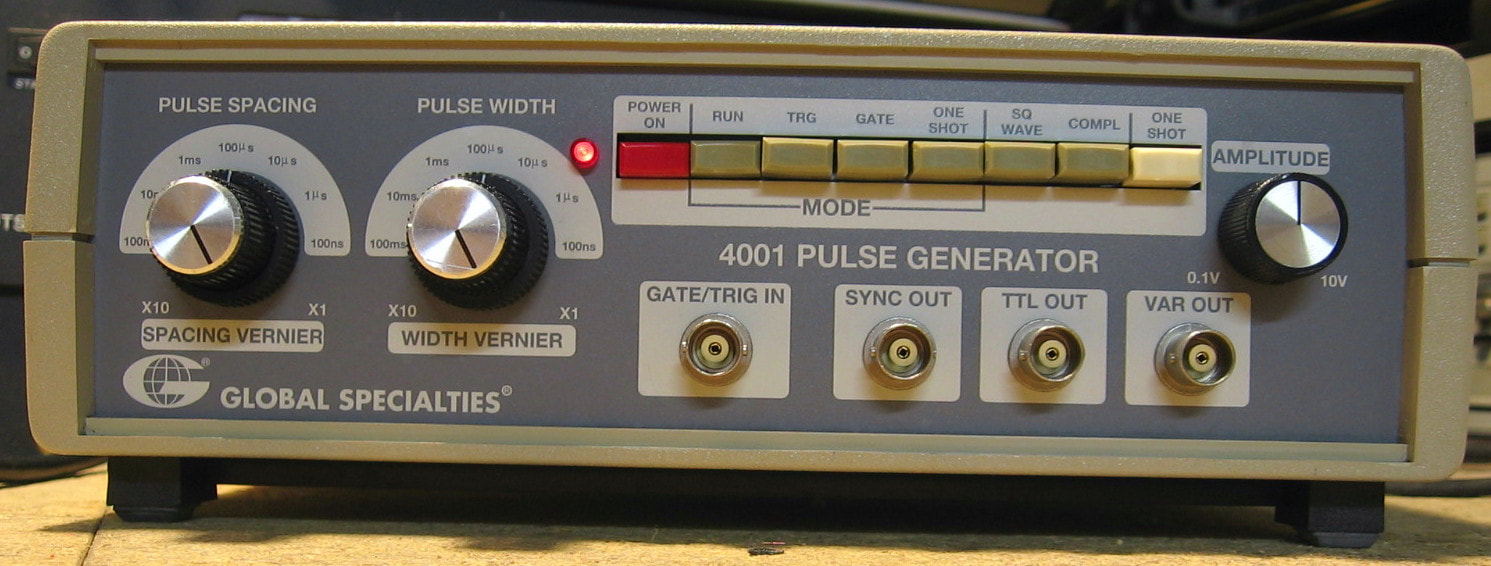
Global Specialties 4001: 5 MHz pulse generator. The 4001 is a basic pulse generator covering 0.5 Hz to 5 MHz with continuously variable pulse widths and spacings from 100 nsec to 1 sec. Has the usual trigger, gate and one-shot functions and has an open circuit amplitude of up to 10 V and rise times of about 20 nsec. Global Specialties is known for producing instruments and accessories primarily directed at the educational market, so one doesn't expect the 4001 to be laboratory-grade. I bought this for $20 (condition unknown) primarily because there was a "Made in the USA" sticker on the back, not "Made in China," and I was curious to see the build quality - it worked fine right out of the box. The build quality is actually fine and the parts selection is first rate. But the entire thing is done with six ICs and six transistors, so it is pretty minimal. In fact, although there is a split power supply producing +18 and -18 VDC, the 4001 uses a single output transistor and can only output positive voltages. For another dollar, they could have had a push-pull output stage and included a DC offset function. My biggest complaint is the cheap plastic pulse spacing and pulse width outer knobs. They have small plastic tabs that meet slots in the metal shaft. The tabs have already worn a bit so there is a tremendous amount of slop in the knobs. And it is only going to get worse since the two rotary switches are extremely tight. They aren't long for this world I'm afraid. (PDF) Grade: B
Had an hour or two to waste one day, so I desoldered the two rotary switches, dissected them, bent the spring pawls to loosen the tension and reinstalled. Now it doesn't take excessive force to turn them.
Had an hour or two to waste one day, so I desoldered the two rotary switches, dissected them, bent the spring pawls to loosen the tension and reinstalled. Now it doesn't take excessive force to turn them.
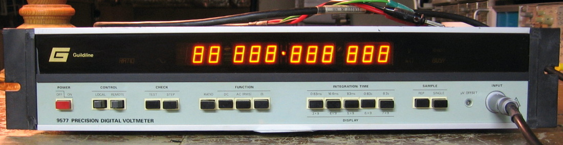
Guildline 9577: 7-1/2 digit DVM. Has plenty of digits as the photo (LED test mode) shows. Too bad it can't use all of them at once (fixed decimal point in the middle). Guildline (and Solartron) made a big, big deal about how their design, which is counter based, is soooo much better than the dual slope integration design that HP and most everyone else used at the time. They claim specs that exceeded HP's. But in my experience, it is simply not true. For instance, the linearity is simply horrid. Adjust the 1V and 10V calibration pots to be spot on and then watch the thing be off 1/4 mV at 3V. The only spec that is exceeded is the low frequency AC response. Finally, this is one of the hardest pieces to service because the two analog boards are placed one on top of the other with a myriad number of connector cables wrapping around the outside edges. It is virtually impossible to access the bottom board with the rest of the unit intact. Shame on whoever designed this piece. (PDF) Grade: B
Had a bunch of problems when it arrived (like disconnected wires), the most troubling of which was a tendency to drift wildly after a few hours. Despite replacing a bunch of ICs, the best solution was simply to add a small muffin fan to keep it cool.
Postscript: Was playing around with unit recently and noticed that on ohms, an open circuit would read about 5 Mohms and then slowly ramp up to the overflow value of 14 Mohms. Took about 10 seconds. At first I thought the ohms current generator circuitry was faulty, but a few measurements showed the current was rock solid at the correct value. So I suspected something wrong with the input circuitry. Moreover, putting 30V through a 10 Mohm resistor into the 9577 should produce a reading of 15V since at that range, the input impedance is also 10 Mohms. And it did, after about 30 seconds, ramp down from 30V to 15V. It felt as though a capacitor was somehow connected to the input circuitry. And that was exactly the case, because a faulty 7406 relay driver chip had failed and permanently switched in the relay to the ACV circuitry, regardless of whether I was in DCV, ohms or ACV. The schematic was not exactly correct, and I'm not sure whether it was the input relay going to the ACV circuit or the output relay coming back from the ACV. Doesn't matter, because both sides have big capacitors hanging off them. A new 74LS06 restored the unit back to correct functionality.
H : HDW, Heathkit, Hitachi, HLCS, HP, Huntron
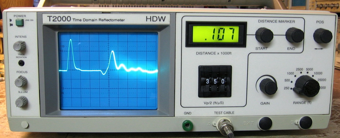
HDW T2000: Time Domain Reflectometer (TDR) circa 1993. Basically a TDR is just like a radar. It sends out a pulse along a cable under test; any fault in the cable causes an impedance change which produces a pulse reflection. This unit has a moderately low bandwidth so the reflections are not very sharp. One must also enter in the velocity factor of the cable in order to accurately convert time to distance. The TDR2000 is very easy to use: 1) set the max distance range, 2) adjust the level control to see the reflections and 3) position the end marker to highlight the reflection peak. Read out the distance on the LCD. (---) Grade: B+
This unit was advertised as "doesn't power up." I suspected it had a switching P/S and would be difficult to fix without the unobtainable service manual. But for $25, I was willing to take a chance. However, upon receipt it powered up just fine. All I did before I plugged it in was to check and reseat the fuse. Could this have been the problem? Probably not. But the end marker pot was extremely noisy, so at least I can claim a "repair" on this one since I replaced it.
This unit was advertised as "doesn't power up." I suspected it had a switching P/S and would be difficult to fix without the unobtainable service manual. But for $25, I was willing to take a chance. However, upon receipt it powered up just fine. All I did before I plugged it in was to check and reseat the fuse. Could this have been the problem? Probably not. But the end marker pot was extremely noisy, so at least I can claim a "repair" on this one since I replaced it.
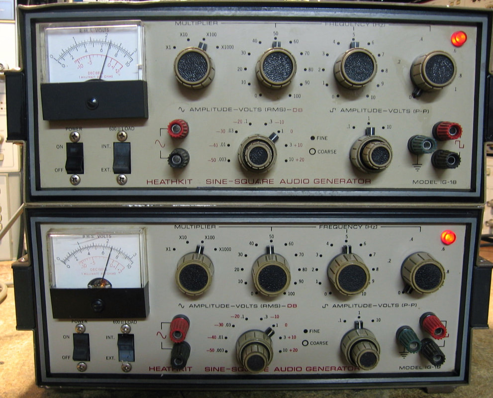
Heathkit IG-18: Sine and square wave generator to 100 kHz. After collecting (and mostly repairing) over 360 pieces, I noticed that I didn't have anything from Heathkit. Not that this is a big disadvantage, since one expects any piece of "test equipment" from Heathkit to be pretty abysmal. And so it is. The IG-18 uses a well known oscillator circuit with a lamp in the feedback. The sine waves are squared up with a Schmitt trigger. The distortion is rated to -60 dBc and it will put out about 10 volts open circuit. These things have somewhat of a cult following since many people have proposed mods to improve the circuitry. For instance, the meter loads down the oscillator and will increase the distortion, so there is a meter buffer mod. Many of these mods are offered on-line as kits including the printed circuit boards. As expected, the untouched IG-18s are laughable compared to a good professional sine/square generator (such as HP). But I do like the big knobs! (PDF) Grade: B-
The eBay buy consisted of two of the IG-18s for $42, not too bad. The seller had a description which almost begged a potential buyer not to buy these due to the extremely rough condition. But I needed something to do for a couple of hours. Mechanically, they were filthy and many of the control shafts were frozen. Some WD-40 cured that. Electrically, one of the units had a cold solder joint on the output attenuator. The biggest problem is the adjustment procedure. There is the "feedback" pot which has to be set just right. And I mean just right. If it is off one way, the thing won't oscillate. If it is off the other way, the distortion goes way up. I managed to get both of them in spec, but there may still be some fiddling around I can do. However, given the efficacy, is it really worth it? I think not.
Postscript: OK, I fiddled around some more. One of these units barely passed the -60 dBc distortion spec. I changed out the light bulb in the oscillator circuit with a 10V bulb from the junkbox. Now this unit is even better than the other one.
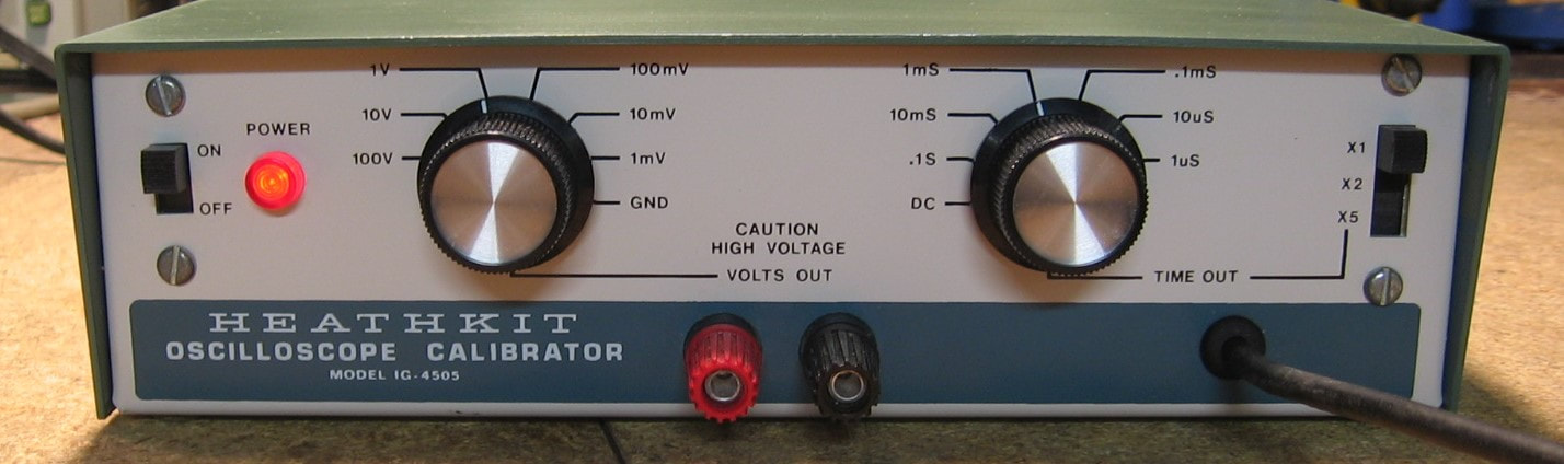
Heathkit IG-4505: Oscilloscope calibrator with a "time" output (square wave with 0.5s to 1us period in a 1-2-5 sequence; 0.2V, 4ns rise time, 0.01% accuracy) and a "voltage" output (1mv to 100V, square wave or DC, 2% DC accuracy). The time output goes through a cable to a 50 ohm terminated female BNC connector and the voltage output is via the front panel banana jacks. The circuit is very straightforward: 1) time output uses a crystal controlled 4 MHz oscillator and some 7474 and 7490 chips to divide the clock down; 2) voltage output is basically a 110V Zener followed by a step attenuator. Obviously, if I really wanted to calibrate an oscilloscope, which typically has about a 1% accuracy in both V/div and time base, I could use my Fluke 5440B DC calibrator (<10 ppm) and HP 5359A Time Synthesizer (<1 nsec) - but where's the fun in that? But it is nice to have one piece that does it all, albeit just as obviously, the IG-4505 is only good for oscilloscopes circa 1980 or earlier But does exactly what it is supposed to do and the build quality is pretty good, especially for a Heathkit. (PDF) Grade: A-
The eBay seller said he turned the unit on, smelled something burning and immediately turned it off. Upon receipt, there was a faint odor, but the thermal imager showed nothing getting overtly hot. While the voltage output was fine, the time output only lasted about 1/4 second before shutting off. This was traced to the first 7474 chip that divides the 4 MHz clock down to 2 MHz. A 74LS74 was installed and all is well. The top cover was badly stained so I repainted it.
The eBay seller said he turned the unit on, smelled something burning and immediately turned it off. Upon receipt, there was a faint odor, but the thermal imager showed nothing getting overtly hot. While the voltage output was fine, the time output only lasted about 1/4 second before shutting off. This was traced to the first 7474 chip that divides the 4 MHz clock down to 2 MHz. A 74LS74 was installed and all is well. The top cover was badly stained so I repainted it.
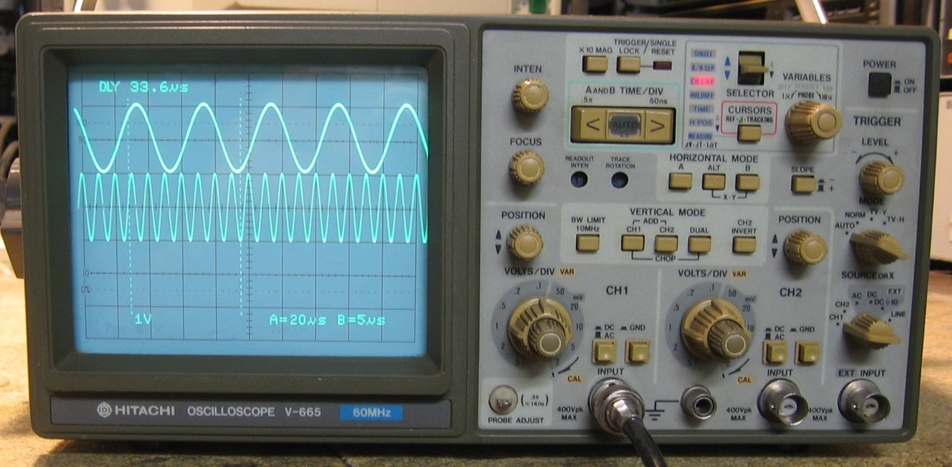
Hitachi V-665: Dual channel 60 MHz analog oscilloscope. It is an analog scope, but has a microprocessor in it for things like cursor readout. This scope is quite a nice piece and has all the features one would want, e.g., dual channel, dual timebase, holdoff, etc., as well as an automatic timebase that tracks the input signal. Hitachi also included a "trigger lock" function. Suppose you are using the holdoff function to get a stable display of a complex waveform. If you change the sweep time, you will usually have to tweak the holdoff. With the trigger lock, the waveform will remain stable through a change of sweep time. Although rated only to 60 MHz, mine will easily trigger up to about 135 MHz. In fact, the schematics seem to indicate that replacing a couple of transistors and capacitors in the input section would raise the bandwidth specification to that of the V-1065, namely 100 MHz (maybe I'll do that one day). The CRT uses 10 kV, not the usual 15 kV, but it seems plenty bright and crisp. The power supply is a switch-mode type and I can hear the high-pitched whine especially when servicing the unit with the covers off (other owners have observed the same thing according to the test equipment forums). The build quality is mostly surface mount componentry and the usual consumer-grade plethora of interconnecting cables between boards. The only things I don't like are the lack of graticule illumination, the fact that the scope defaults to the x10 probe settings for the V/div readout when powered on and the lack of automatic switching of the trigger when changing the input across channels. But on the whole, the V-665 is a fine example of Japanese engineering and design and somewhat better than the other generic Korean analog scopes I have. However, disassembly for service looks like a major chore. (PDF) Grade: A-
I paid $75 shipped for this, including two Hitachi 1x/10x probes, which isn't too bad. The eBay photo showed the unit displaying only the text annotations at the top and bottom, not any trace. At first, I thought this was likely due to the trigger switch being selected to "norm," instead of "auto." But upon receipt, I didn't see any trace when I switched it to "auto" either. Then I turned up the intensity knob and voila. D'oh. The intensity knob controls only the brightness of the waveform; there is a separate control for the brightness of the text. I was fooled into thinking that if I saw text, then the CRT brightness was set correctly for everything. Silly me. Everything seemed to work OK, but I ran through the calibration procedure just in case. And I did notice that someone must have been inside before, because several screws holding down circuit boards were missing. These Hitachi scopes are notorious for dirty/broken switches/pots, but everything seemed to be OK except for the variable V/div knobs on both channels, cured with a spray of contact cleaner.
Postscript: Recently came across an eevBlog forum entry describing a hack to enable the frequency counter option on a Hitachi V-1065 scope. The V-665 board looks identical, so I applied the hack to my scope (move a jumper to an adjacent set of pads). Sure enough, I now have a frequency counter as the fourth option in the cursor readout selection. But as the eevBlog discussion also said, the frequencies displayed are not particularly accurate, possibly due to the clock being a resonator, not a crystal. My frequency readout is consistently 0.55% low. Close enough. If I need precise frequency measurements, I won't be using a scope anyway.
Postscript^2: I took the scope back apart and indeed there was a 12 MHz ceramic resonator, not a crystal, supplying the microprocessor. A quick touch with my oscilloscope (which adds some capacitance to ground) raised a 994.5 Hz frequency display for a 1 kHz input signal up to 996.5 Hz. So clearly adding some capacitance will improve things. I soldered in a 65 pF capacitor and now my V-665 frequency readout is spot-on (+/- one least significant digit).
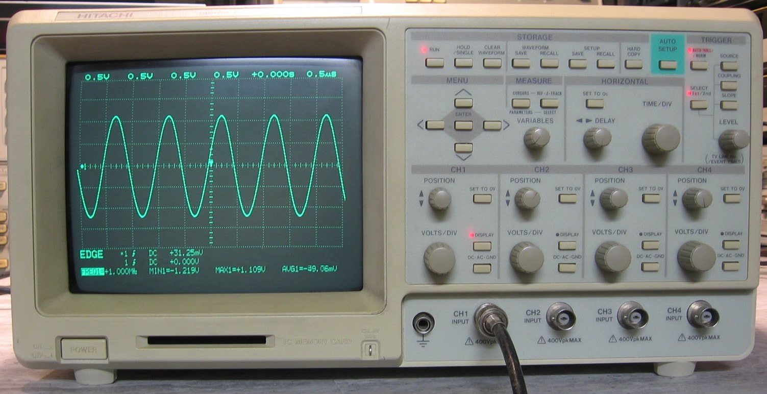
Hitachi VC-7104: 150 MHz, four channel digital oscilloscope. I had bought an old HItachi V-665 analog scope a few months earlier and was very impressed with it, so I thought I would try out Hitachi's digital foray. Boy was I disappointed. This oscilloscope is an absolute dog and it is no wonder why I can find virtually no information about it on the web. Hitachi probably made a few then aborted the whole idea. The scope runs very slowly (e.g., turn a vertical position knob and watch all the traces disappear for a second while it redraws everything) and the man-machine-interface/menu system is horrendous. The scope has four AD9002 150 MHz A/D chips, but only samples at 100 MHz. It goes into equivalent sampling mode at about 0.2 usec time division. There are functions included that shouldn't be, like go/no-go decisions, and functions not included that should be, like trigger holdoff, variable V/div and time/div, split-screen zoom, and on and on. It is almost like whoever designed this only had a rudimentary understanding of how people typically use oscilloscopes. I originally thought that the VC-7104 would be almost a direct copy of my Iwatsu DS-9122 since both are examples of Japanese digital oscilloscopes from the early 1990's. However, the DS-9122 is a much better version. On the other hand, both have thermal printers which are quite handy. The build quality and parts selection of the VC-7104 is excellent and everything disassembles without too much fuss. But try working on this scope when you need it powered up with all of the boards installed. Virtually impossible. (---) Grade: B-
The eBay listing photos showed the scope's built-in calibration results: Interpolator = Pass, 2nd Atten Bal = Fail, Vertical Position1 = Fail, Vertical Gain = Fail, Vertical Position2 = Fail, Trigger Gain and Level = Fail. Hey, one out of six ain't bad! Moreover, one of the photos of a displayed waveform showed pieces of a waveform with gaps in between and not aligned in time properly - this was only seen at fast timebases when the unit dropped into equivalent sampling mode. When I received the scope, the power supply was erratic and nothing good was on the CRT. It was clear that there were major problems and the one and only one forum entry I found on the web suggested to replace all the SMT electrolytic caps and inductors on the vertical pre-amp and digitizer boards. 131 component replacements later (about half of the caps and a couple of inductors that I pulled were faulty) I now had two of the four channels with huge DC offsets and a clipped waveform could only be seen at the bottom of the screen at certain V/div settings. Moreover, those channels had no high frequency response. Along the way when one of the digitizer boards failed, I also discovered an open resistor on that board. Meanwhile, the Lambda LVQ-130 power supply still didn't work properly and was drawing random amounts of power from the AC line and exhibiting momentary dropouts of the 5V output (which reset the scope's uP). Despite about a week's worth of trying, I never did get the LVQ-130 to be stable. Finally I gave up and purchased two Meanwell power supplies (RS25-5 and RT-125C) and mounted them where the old power supply was. To get the two faulty vertical channels to work, I compared voltages between a working vertical pre-amp and non-working vertical pre-amp board. I found a section of the faulty board where the voltages differed. This was ultimately caused by the lack of a 12V power rail to that portion of the board. Evidently these are multi-layered boards because there are many through-holes that are not connected to visible traces on both sides of the boards. And evidently all the electrolyte that leaked over the years damaged the internal layer connections. Both faulty vertical pre-amp boards had exactly the same problem and both were fixed by simply running a wire from a good 12V power rail to the damaged section. And still, two of the four input channels only measure about 500k input impedance, not the desired 1M, and slowly increase in resistance as seen by an ohmmeter. So I suspect there is still some damage to these boards. With all of these repairs, all four channels work, but there still is a big problem with the self-calibration. The scope now passes five out of six calibration steps (fails the Vertical Gain). There are several pots/caps that can be adjusted on the vertical boards, but it is extremely difficult to pull a board out and make adjustments, especially because after a tweak, you have to wait a few minutes to see if the calibration procedure will successfully complete. And without a schematic or a service manual, it is kind of hard to tell what all the adjustments do. Moreover, unlike the Iwatsu DS-9122 which will tell you exactly what channel and what V/div setting failed the gain calibration, the VC-7104 provides no information. So you don't even know which channel to try and adjust. I assume that none of the computed calibration constants are stored when the VC-7104 fails calibration. I'm hoping in a perfect world that if I ever get things to pass, maybe the gaps I am seeing in equivalent time sampling mode will be corrected as part of the scope's interpolation calibration. We'll see, but I think I am pretty much done with this piece.
Postscript: A few weeks later, I tried one last time to get this thing to pass all of the calibration steps. While doing so, I noticed that the 5 mV/div setting on channel #3 was faulty. Since I heard relays clicking on every single mV/div setting, the likely culprit was a faulty relay. I pulled the vertical pre-amp board out and did some relay testing with an external 12V power supply. I did find one relay that was not making contact in the normally closed position. While I was checking the other relays, I inadvertently fed the coil with reverse polarity and destroyed the inductive kickback protection diode across the coil. I replaced the faulty relay and the diode and that fixed the missing 5 mV/div problem. However, as mentioned before, channels #2 and #3 still have input impedance problems and thus gain problems, and this forces the calibration procedure to fail. I am about as far as I can get with the VC-7104 until a service manual becomes available. The gaps in the displayed waveforms are down to about 1-2 nsec and I'm guessing will be gone if the thing were ever to pass calibration. Meanwhile, the scope is perfectly usable, and perfectly accurate on channels #1 and #4, and might be useful once in a while in my lab because of the very convenient thermal printer.
Postscript^2: Six months later and I thought I would give it one more try. I took out all four preamp/atten modules and all four digitizer boards, then put one pair in the rightmost slot so I could adjust it while the scope was powered up. By trial and error with a square wave input at various frequencies and amplitudes, I managed to adjust the preamp/atten board fairly well. Then I repeated the exercise with the other three pairs. I put everything back together and ran the calibration. This time, everything passed! Moreover, since the calibration passed, the cal parameters got stored and as I suspected, the 1-2 nsec gaps in the displayed waveforms were finally gone. Moreover, the impedance problems on channels #2 and #3 (at V/div settings > 20 mV/div) also disappeared. I don't have any explanation for why a successful calibration would correct the flakey input impedance. Perhaps the leaking electrolyte finally dried up.
HLCS HS1010: This is a 0-200,000 Lux meter with auto-ranging and measurement storage, with a claimed +/-5% basic accuracy. Sure, go ahead and drop $1K on a professional model; this one was <$13 delivered to my door, batteries included. So inexpensive that the Chinese must have farmed it out to Bangladesh. I'm including it on this test equipment web page because theoretically I could use it to adjust the front panel lamps of all my equipment to the same brightness. Now, if I only had a lux meter calibrator ... (OM) Grade: B+
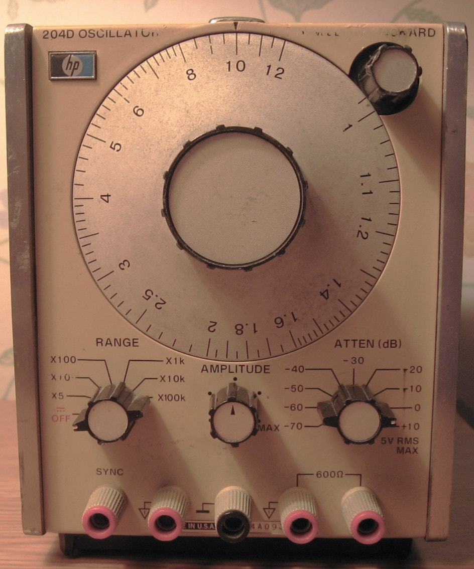
HP 204D: Audio oscillator, 5 Hz to 1.2 MHz, 600 ohm output impedance, 5 Vrms open circuit. Although I certainly have better oscillators and/or function generators, I bought this piece mainly because of its historical significance. HP introduced the 204B in 1961 as the first transistorized and battery-powered audio oscillator. They followed it up with the 204C in 1968 which had better specs. I have the 204D which is essentially a 204C with an output attenuator. Fortunately, mine doesn't have the battery option since we all know that the batteries will either leak eventually or need (expensive) replacement. The frequency dial isn't particularly accurate, there is no "calibrated" amplitude, the distortion is OK at <-60 dBc, but otherwise does what it is supposed to do. Only needed some cleaner squirted into the switches to get it working properly. (PDF) Grade: B+
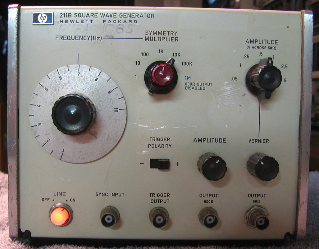
HP 211B: 10 MHz square wave generator, controllable duty cycle, high voltage output (60V open circuit from 600 ohms jack). A simple utilitarian HP offering. Sold for very little cash in its day. (OM) Grade: C+
Had several faulty electrolytic capacitors. Replaced them.
Had several faulty electrolytic capacitors. Replaced them.
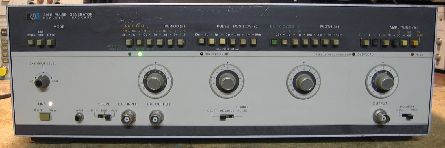
HP 214B: High Power Pulse Generator to 10 MHz with 100 volt output (maximum repetition rate in the 30-100 volt range is 4 MHz) and pulse widths down to 25 ns. I can't imagine why any home lab would need such a beast, but HP's catalog says it is good for laser diode pulsing or transient simulations. I suppose I could hook it up to my outside ham radio antenna and wipe out most of the HF band for miles and miles. Uses two E130L power pentodes and does the usual external triggering and gate functions. The four main controls, frequency, delay, width and amplitude all have vernier potentiometers. However, I find the controls somewhat confusing at best, especially concerning the constant duty cycle capability which allows the unit to control the pulse width based on duty cycle, independent of pulse rate. As complicated as this beast could have been, HP-Germany designed the unit to be among the most easily serviceable - almost everything is easy to get to. (PDF) Grade: B+
I was expecting the worst, namely missing and/or broken output tubes, but they were intact and the piece generally electrically was fine. Mechanically it was missing three of the pushbutton caps, but these were sourced from my junkbox courtesy of a defunct Fluke 8502A front panel. The frequency, width and delay 10K vernier pots were all shot and were replaced. Alignment was non-eventful.
I was expecting the worst, namely missing and/or broken output tubes, but they were intact and the piece generally electrically was fine. Mechanically it was missing three of the pushbutton caps, but these were sourced from my junkbox courtesy of a defunct Fluke 8502A front panel. The frequency, width and delay 10K vernier pots were all shot and were replaced. Alignment was non-eventful.
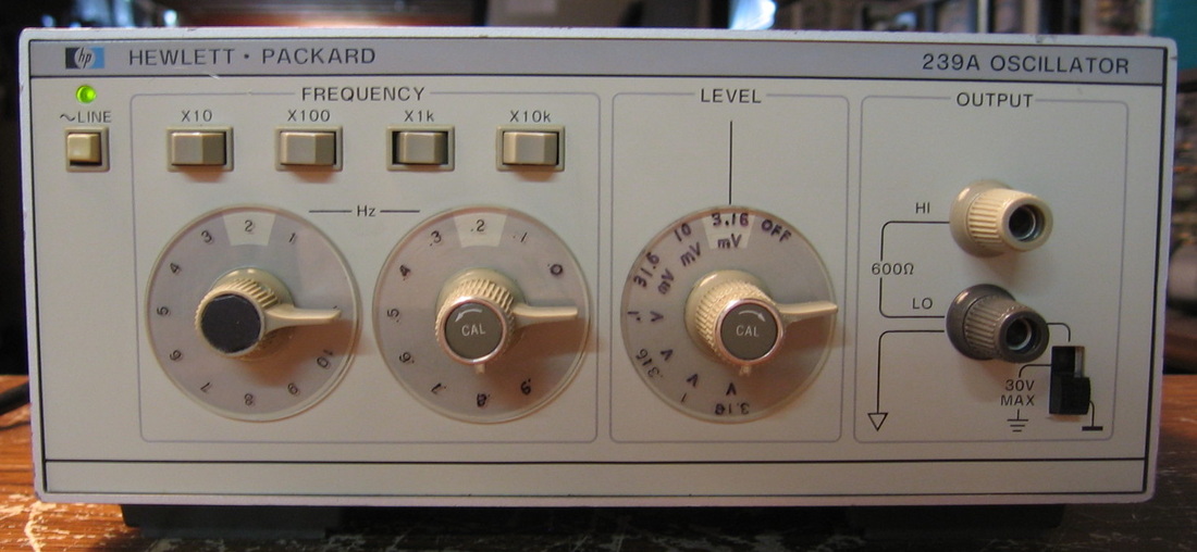
HP 239A: Low distortion oscillator, 10 Hz to 110 kHz, +10 dBv to <-50 dBv. Distortion measures less than -98 dBc at 1 kHz full scale output. The last true analog (Wien) oscillator HP produced (~1979). This is one of the lowest distortion oscillators HP ever produced. I guess their last was their best. A close variant is also used in the HP 339A distortion meter. I bought it to test the HP 8903A audio analyzer which can measure down to -100 dBc as the only other signal generator I had produced about -70 dBc best case (HP 3326A). ($CD) Grade: A
Pretty easy fix. It had a loose cable from the amplitude vernier pot to the main board. Also repaired the knobs.
Pretty easy fix. It had a loose cable from the amplitude vernier pot to the main board. Also repaired the knobs.

HP 241A: 1 MHz pushbutton oscillator. A mid-era entry in the extremely successful and long-lived HP 200 series, which started with the HP 200AB, based upon Hewlett's 1938 resistance-tuned design, continued with the HP 200CD in 1952, which was listed in the HP catalog for an astonishing 33 years, and ended in the 1980s with the HP 239A which achieved a -95 dBc distortion specification. The HP 241A, introduced in 1963, uses a Wien bridge oscillator which normally produces very low distortion, yet the specification is only 1% (my unit measures 0.5%). The output ranges from -30 to +10 dBm (re 600 ohm output impedance). The frequency accuracy is +/-1%, but the repeatability is at least an order of magnitude better. And that was the whole point of the 241A - the HP engineers wanted to give the user repeatability one could not achieve with the usual tuning dial. Instead of continuous tuning, you get 4500 discrete frequencies (with three digit selection). As far as accuracy and repeatability, my unit seems to be consistently about 0.5% low in frequency. Given that adjustments are made by padding capacitors, I shall leave it that way. However, it is very repeatable. I can set it to 1 kHz, read 994 Hz on the counter, play with the unit for 30 minutes, and it will go right back to 994 Hz (within 0.03 Hz). My favorite spec, however, is the AC power: one measly watt! (PDF) Grade: B+
For a unit that is 49 years old, I was expecting far worse than I got. The piece was missing the fuse/holder and the previous owner had rigged up some strange fuse arrangement. So I put the right holder in. The neon power lamp was burned out and so was replaced. The amplitude and vernier knobs got a squirt of cleaner which improved them to about 95% noise-free. The banana jacks were pretty worn and abused and I had the exact same one sitting in my junk drawer from an old defunct HP 410C, so in that went. Somewhere during its life, the "x1 kc" button was lost and was replaced by a "x10 kc" button. Great, now I have two of those. I would have liked to paint over the 0, but I couldn't get a satisfactory look, so I simply added a small red decimal point between the 1 and 0. Electrically, there was a brief period where the amplitude gyrated wildly by merely tilting the unit. It went away eventually, but maybe it was all the whiskers in the caps and/or transistors that finally burned away. It seems fine now and passes the performance specs.
For a unit that is 49 years old, I was expecting far worse than I got. The piece was missing the fuse/holder and the previous owner had rigged up some strange fuse arrangement. So I put the right holder in. The neon power lamp was burned out and so was replaced. The amplitude and vernier knobs got a squirt of cleaner which improved them to about 95% noise-free. The banana jacks were pretty worn and abused and I had the exact same one sitting in my junk drawer from an old defunct HP 410C, so in that went. Somewhere during its life, the "x1 kc" button was lost and was replaced by a "x10 kc" button. Great, now I have two of those. I would have liked to paint over the 0, but I couldn't get a satisfactory look, so I simply added a small red decimal point between the 1 and 0. Electrically, there was a brief period where the amplitude gyrated wildly by merely tilting the unit. It went away eventually, but maybe it was all the whiskers in the caps and/or transistors that finally burned away. It seems fine now and passes the performance specs.
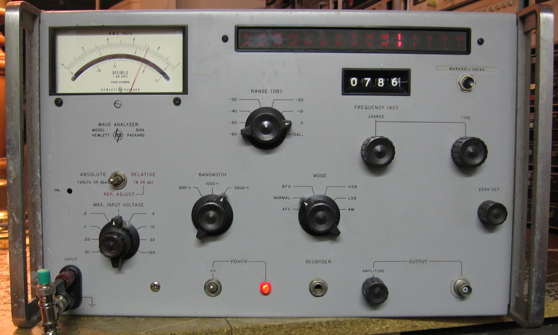
HP 310A: Wave analyzer to 1.5 MHz. A wave analyzer is nothing more than a fancy receiver with an accurate voltmeter. In later years, HP called these things selective voltmeters, since one can also view them as a voltmeter with a very good preselection filter in front of it. See the descriptions for the HP 3586B, HP 3581C, Cushman CE-24A and Wandel & Golterman SP-19. One of the nice things about the HP 310A is that is has an AM demodulator, something the other units do not have. Bandwidths are 200 Hz, 1000 Hz and 3000 Hz and amplitude ranges from 10 uV to 100 V full scale. Has the 100 kHz crystal calibrator option which must have been quite a novelty in the mid-60s. (PDF) Grade: B-
Being built in 1968, I expected a few problems upon receipt and I wasn't disappointed. The meter scale had begun to flake and was catching the needle. I dissected the meter and repaired the damage. There was no response to any input signal I tuned to until I noticed that the frequency readout was about 140 kHz too low. To remove the complete tuner unit and roll the turns counter to the correct frequency took about 3 hours. All the gears were frozen to their shafts so I really have no idea how it could have moved 140 kHz. The AFC did not lock properly and the problem was traced to a faulty electrolytic capacitor. I disabled the AFC cutout relay that was preventing a proper adjustment. There are still probably some marginal semiconductors in the AFC circuit, but many are HP-selected germanium transistors and I'm not about to spend $25 a pop for those. The thing is a bit noisy and suffers from microphonics if you bang on it. The switches and pots are about what I would expected for something >40 years old. Summary: basically fixed, but I'll keep plugging away at my leisure.
Postscript: Replaced all 23 2N2189 germanium transistors with 2N3702 silicon transistors as per an HP service bulletin I found online. Everything now adjusts properly including the AFC circuitry.

HP 312B: Wave analyzer, selective level receiver, call it whatever you like. The (ten year) follow-up to the HP 310A without all the germanium transistors. Frequency range to 18 MHz. Will comfortably measure signals down to about -115 dBm. This shares the basic design with the 310A including a pesky notch right at dead center of the tuning frequency (presumably their active filters couldn't handle DC) and a somewhat flaky Automatic Frequency Control (AFC). Unlike the 310A which uses a very precise variable capacitor and a mechanical turns counter for the frequency readout, the 312B gets by with a more modest variable capacitor and a digital counter to figure out what the frequency is. (PDF) Grade: A-
There was nothing really wrong electrically with this unit except for a faulty output amplitude pot, which was suitably replaced. Cosmetically it was in very rough shape with broken plastic windows, broken knobs and mountains of sticker residue. Some glue, new knobs, cleaning solvent, and what you see is what I got.
Postscript: Many years later, turned this unit on and after about one minute, the display froze and the controls were unresponsive. Checked the +20 and -15 volt supplies and the +20 was reading about 0.6 volts. It was an easy fix - A1C4, a 15 uF, 20V Sprague solid tantalum capacitor that had shorted. Being a Sprague capacitor is bad enough, but why did HP spec a 20 WVDC cap on a 20 V line?.
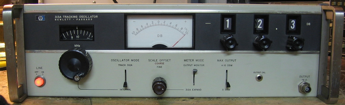
HP 313A: Tracking generator specifically mated to HP 312B selective level receiver. The HP 313A is basically just a sine wave generator, covering 10 kHz to 22 MHz, with levels from 10dBm to -99.9 dBm (75 ohms) in 0.1 dB increments. It can run as an independent signal generator or as a tracking generator with three cables to the HP 312B. With the tracking generator function, one has the (early) beginnings of a scalar network analyzer. As a somewhat curious bonus, the HP 312A meter can expand 2 dB of the HP 312B's meter with 0.02 dB ticks. This meter expansion was later included all by itself within the HP 312 "D" model. Typical early 1970's overbuilt HP design. I guess this concludes my network analyzer collection as I now have the paired HP 312A/312B, the HP 3336B/3586B, the HP 3330B/3570A and the Wandel & Goltermann PS-19/SPM-19. (PDF) Grade: B
Everything worked fine when received. One of the electrolytics in the P/S had leaked a lot of electrolyte and was therefore replaced.
Everything worked fine when received. One of the electrolytics in the P/S had leaked a lot of electrolyte and was therefore replaced.

HP 332A: Manual distortion meter. This piece is virtually identical to the HP 334A (see below) except that it is absent the automatic notch tuning feature. Everybody should be forced to do distortion measurements at least once manually before having the luxury of automatic tuning - it builds character! Mine has the label Option H01, which usually means it was built for the telephone company or some Government agency. What is strange, however, are the markings surrounding the meter range switch. On all the other HP distortion analyzers (331A, 332A, 333A and 334A), the dB markings follow the percentage markings. In other words, a distortion of 1% is -40 dB. But if you look at my piece, you will see 1% corresponds to -50 dB, clearly wrong as are all of the other dB values. I scratched my head for a while until I realized that the scale is dBm, not dB, on my unit. Why HP marked it this way might have something to do with the Option H01, but I really don't know. (PDF) Grade: B
One of the electrolytic caps in the metering circuit was shorted, hence replaced. Being full of Sprague caps, they all eventually will need replacement. The unit probably needs alignment since the photo shows a reading of 11% distortion for a 1 kHz triangle wave - it ideally should be 12%. Maybe I'll get around to the adjustments, maybe not.
One of the electrolytic caps in the metering circuit was shorted, hence replaced. Being full of Sprague caps, they all eventually will need replacement. The unit probably needs alignment since the photo shows a reading of 11% distortion for a 1 kHz triangle wave - it ideally should be 12%. Maybe I'll get around to the adjustments, maybe not.

HP 334A: Automatic distortion meter, fundamental to 600 kHz. All of these distortion meters basically work the same way. They remove the fundamental with a narrow notch filter and the surviving energy (harmonics plus noise) is measured by the meter. HP uses a feedback loop to tune the notch, although you can do it manually if you have steady hands (and a steady input signal). (PDF) Grade: B
Found shorted cap in the feedback circuit, shorted cap in the P/S. Replaced all the electrolytics in the unit.
Found shorted cap in the feedback circuit, shorted cap in the P/S. Replaced all the electrolytics in the unit.
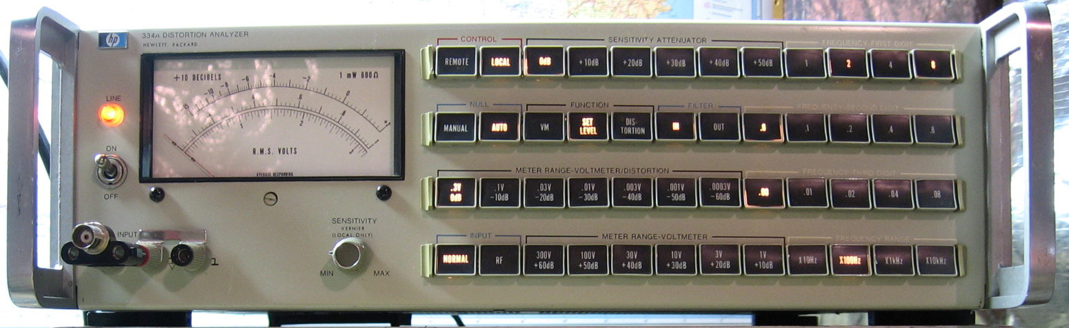
HP 334A (special telco version): Automatic distortion meter, fundamental to 150 kHz. This is a curious piece that I can find no information on. Presumably it was built for the telco industry. They removed all the manual controls from the stock HP 334A and made everything pushbuttons. The real reason to do this is so they could parallel a port on the back panel for computer control. Why they reduced the frequency response from 600 kHz to 150 kHz is beyond me. This unit is packed to the brim with boards, much more than the stock 334A. (OM) Grade: B+
This piece continues to be a maintenance nightmare. I have already fixed some loose push-on connectors and replaced the faulty bulbs in the bridge circuit. But one day, the distortion function didn't work at all. I traced it to two reed relays that were showing near infinite when closed. One of them was cured by banging on it. The other one was cured by hooking up a 1 pulse per second square wave and letting the relay cycle for 30 minutes. But there about 75 reed relays in this thing and I'm betting I'm not done yet.
Postscript: Yup, ain't done yet. Every time I turn this piece on, which is about once per year, I have to take it apart and bang on all the reed relays and/or reseat the boards. Would benefit from replacing all the relays which has less of a chance in my lifetime than us having a permanently manned base on Mars.
Postscript^2: Well, I'm not going to replace all the relays, but I did remove all of the boards and test all 91 relays on the bench with a 5 volt
power supply and a continuity tester. I found three faulty relays (two open, one that stuck closed for a while) and these were suitably replaced. I had several hours of terror when the 334A would then sometimes completely work fine and sometimes completely not work fine. Moreover, a brief tug on the chassis would sometimes change this condition. Sounded like a ground was missing and indeed that's what I ultimately think the problem was. Rather than run ground traces all over a particular board, HP decided to run portions of the ground trace to where the mounting screws to the metal chassis were, relying on the chassis for continuity across the board. One of the captive nuts for a screw worked loose and I didn't tighten it enough to make a solid contact. Hence part of the board's ground was missing. Twisting on the chassis a little moved the nut microscopically and the unit would sometimes work. Anyway, all fixed now. I also ran through the calibration procedure since I don't remember ever doing it when I first got the piece. It was way off, so I guess I remembered correctly.
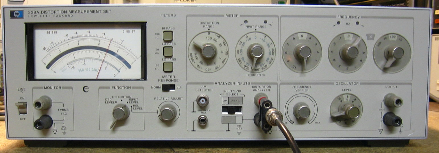
HP 339A: Automatic distortion meter, fundamental to 110 kHz. The 339A was the culmination of the HP 33X series of analog distortion analyzers until HP came out with the 8903 (digital) model. Unlike my 334A the 339A also contains a very low distortion Wien oscillator, essentially a replica of the HP 239A oscillator (see entry for the 239A above), capable of approaching -100 dBc distortion. The 339A itself can measure distortion below -80 dBc and also has an AC voltmeter and AM detector. Operation is pretty simple. Hook up your input signal, dial in the approximate fundamental frequency until the high/low LEDs are off, dial in the voltage range until the high/low LEDs are off, and then select the distortion function. Keep down ranging the distortion dB knob until the meter is in range. The fine amplitude and frequency are adjusted automatically for you. My unit seems to work wonderfully. Hook up the internal oscillator to the distortion input and watch the thing read -98 dBc at 1 kHz. (PDF) Grade: A
The only thing really wrong with this when received was a loose meter. Indeed, the mounting clips had worked loose. But fixing that required pulling the front panel, which was a one hour chore. And I inadvertently shook a few cables loose, so I had to track those down after I reassembled the front panel and the unit didn't work. But it's all fixed now. One of the banana jacks had also cracked loose, but was easily epoxied back together.
The only thing really wrong with this when received was a loose meter. Indeed, the mounting clips had worked loose. But fixing that required pulling the front panel, which was a one hour chore. And I inadvertently shook a few cables loose, so I had to track those down after I reassembled the front panel and the unit didn't work. But it's all fixed now. One of the banana jacks had also cracked loose, but was easily epoxied back together.
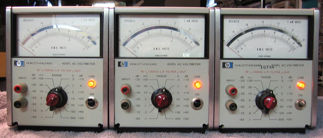
HP 400FL: AC voltmeter, 20 Hz to 4 MHz, 100 uV to 300 V full scale. Even though these are average responding, not true RMS, they have their uses. The only annoyance is the non-overlapping of the ranges. (OM) Grade: B+
Five of these came in one package. The usual mix of faulty electrolytics and bad mechanical parts. Fixed four, gave two away, kept the fifth for spare parts.
Five of these came in one package. The usual mix of faulty electrolytics and bad mechanical parts. Fixed four, gave two away, kept the fifth for spare parts.

HP 403B: AC voltmeter (average responding) similar to the HP 400FL, 5 Hz to 2 MHz, 1 mV to 300 V full scale. Designed to run off of (mandatory) batteries, but has a built-in AC battery charger. (PDF) Grade: B-
I thought I was in for a disaster since the internal batteries should have leaked all over the insides. However, I was pleasantly surprised to see that the previous owner had cleaned it all up and installed new batteries. But there were some loose binding posts and a disconnected wire that I still had to remedy. I also replaced all of the electrolytics for good measure. The only annoyance with this unit is that it takes about 30 seconds to warm up. During that time, the meter bounces up to full scale a few times. I calibrated the meter and it meets all the specs, so I'm not going to worry about the initial fluctuation too much.
I thought I was in for a disaster since the internal batteries should have leaked all over the insides. However, I was pleasantly surprised to see that the previous owner had cleaned it all up and installed new batteries. But there were some loose binding posts and a disconnected wire that I still had to remedy. I also replaced all of the electrolytics for good measure. The only annoyance with this unit is that it takes about 30 seconds to warm up. During that time, the meter bounces up to full scale a few times. I calibrated the meter and it meets all the specs, so I'm not going to worry about the initial fluctuation too much.
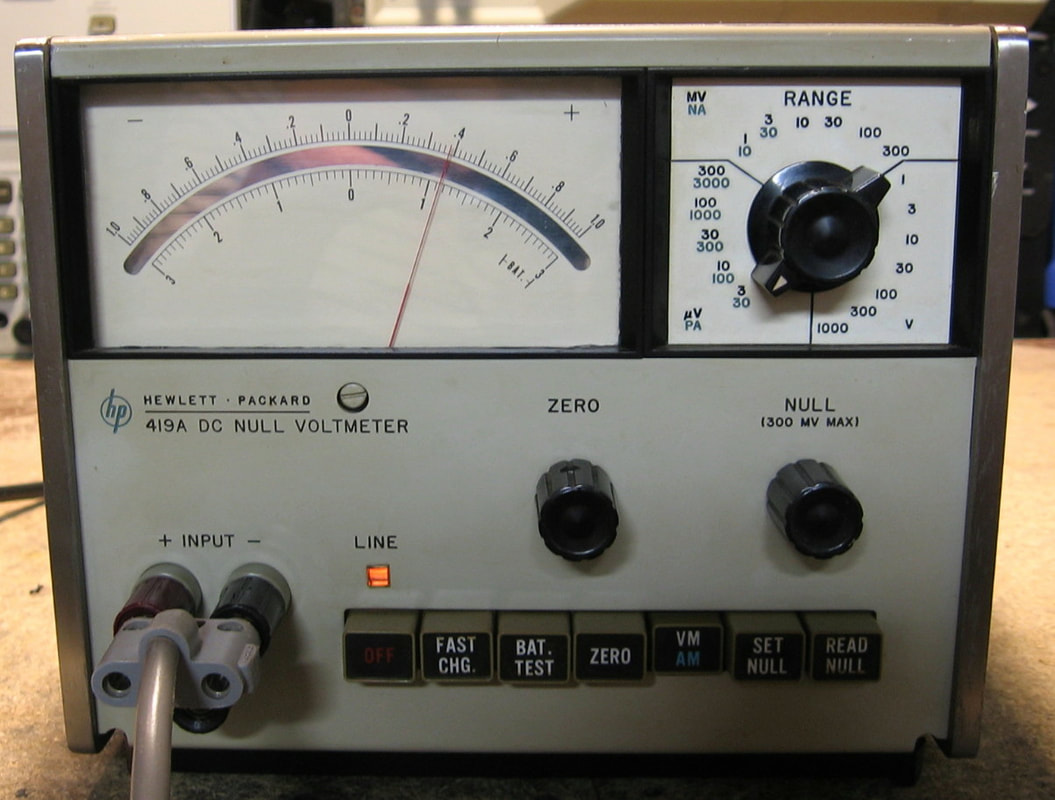
HP 419A: DC Null Voltmeter: Although the 419A will function as a standard DC voltmeter, its real utility is as a null meter; such a beast is used most often to compare two voltages, as in calibrating a voltage source to a standard. It is very similar both in circuit design and performance to my Fluke 845AR (see the description for that item) so I won't bore you with the specs. Although the Fluke 845AR has a 1uV full scale setting, the HP 419A only goes down to 3uV full scale. However, the meter is so much nicer (larger) on the HP, you really don't suffer too badly and can easily interpolate down to tens of nanovolts. One nice feature of the 419A, absent in the 845AR, is the ability to achieve basically infinite input impedance at the null. This is done through the use of a bucking voltage supply (1.35V battery) that is switched into the circuit to "cancel" out the input, and then reversed in polarity to produce the final voltage reading. Of course, the 1.35V mercury batteries are no longer available, but there are easy alternatives available. The photo of the 419A shows the reading against 1uV obtained from my Fluke 343A DC calibrator, set to 100uV, feeding my ESI RV622A divider, set to 0.01. Produced in the mid 1960's to mid 1970's, the 419A must have been pretty impressive at the time. Some fifty years later, it still is pretty impressive. (PDF) Grade: A-
The seller offered no description as to whether or not this piece worked and naturally I assumed the worst. And I wasn't disappointed as the NiCd batteries were completely toast and had corroded quite a few nearby connectors. I removed the batteries, cleaned up the corrosion and installed two 12V Zeners where the batteries had been (the 419A can run off of AC power). Powered the thing up and - absolutely nothing. There was +/-12V present on my Zeners but that was as far as the voltages went; the two circuit boards had zero power. The P/S voltages are actually distributed through the pushbutton switches and a quick check with an ohmmeter showed that almost all of the switches had infinite resistance when closed. I blasted the whole set with contact cleaner, worked the switches a few dozen times, and that did the trick. The 1.35V mercury battery tested fine, but the battery holder had cracked. I thought about gluing it all back together, but there was so much corrosion on the contacts, I simply cut the wires and soldered them directly to the battery. The only other obvious defect was the glass in front of the meter which had dislodged and was preventing the needle from swinging to the right. It wasn't too bad to pull the meter, take it apart and glue the glass back. But I had to pull it out a second time because when I first put it back, I didn't notice that I had dislodged the neon power-on light.
Postscript: While everything seems to work fine, and all the readings are accurate, I've noticed an anomaly with the response time. I'm getting about 3 seconds for a full-scale reading, except on the 3uV, 10uV, 10mV, 100mV and 1V ranges where it is about 7-10 seconds. OK, I can see the lowest 3uV range having a longer time (and that is even acknowledged in the manual), but why the other ranges? And why, for instance, are the 1mV and 10V ranges fine while the 10uV, 10mV, 100mV and 1V aren't? A total mystery to me, because it doesn't look like there is anything special going on with those ranges according to the schematic. I can see if ALL the ranges had an excessive response time, there would probably be a circuit problem. And I would be satisfied if the offending ranges didn't produce accurate results. But all the readings are fine. I shall study the schematic more carefully, because something must be going on. Stay tuned...
Postscript^2: A4R26 (nominally 10K) is supposed to control the response time. Early on in the repair, I tried paralleling resistors across it to lower the time, but to no avail. In desperation, after trying a bunch of capacitor substitutions, I tried R26 again. But I think I had identified R26 incorrectly on the board the first time because this time the response time did adjust. I ended up at about 1K which gives me a nominal response time of about one second on almost every ranges (there are a couple of oddball ranges where it climbs to about 2-3 seconds). Done.
Postscript^3: Many months later, I turned the 419A on and it wouldn't zero - it could only adjust to about -30 uV with the front panel knob. The knob controls a pot which selects a voltage from -0.6 to +0.6 VDC. These voltages are derived from the +/-15 V rails through 56K resistors to two diodes. The +/-0.6V is tapped off the diodes. So I replaced the two diodes with two 2 V Zeners and dropped the two 56K resistors to 10K. Now I have enough voltage range to get the thing zeroed. Seems no worse for wear otherwise. Whether some components drifted out of tolerance, I don't know - this fix was simpler.
Postscript^4: I guess I was too clever for my own good because one day later, the 419A is back to its old tricks, namely the zero control doesn't have enough range. I tried scrubbing the amplifier board, scrubbing the range resistors, a heat gun, cold spray, you have it. Every time, it would temporarily fix the damn thing, but 15 minutes later it was back to malfunctioning. I removed my Zeners and went back to the original configuration since obviously that wasn't my problem. The voltage developed by the zero pot goes through a 3 Mohm resistor back into the chopper neons as part of the feedback. OK, the 3 Mohm resistor read 3.1 Mohms, still within the 5% tolerance. But I noticed that the HP 3420A differential voltmeter has essentially a copy of the HP 419A inside and the schematics are virtually identical. Except that the 3420A doesn't use a 3 Mohm resistor, it uses a 1.8 Mohm resistor. I figured more is better and simply paralleled a 1 Mohm resistor on top of my 3 Mohm one. I've now run it three times from a cold start and it seems perfectly fine. Again, this all might be explained by marginal neons, so I'll keep an eye on it when I turn it on again in another year.
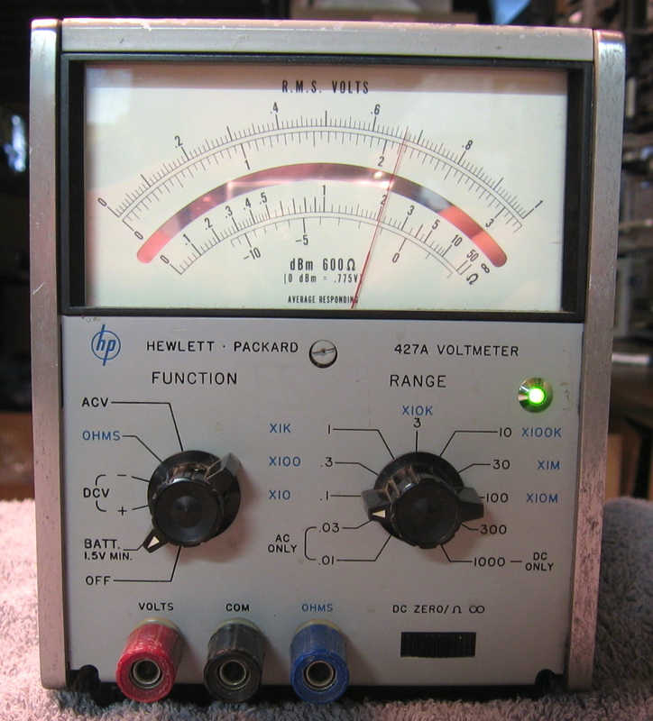
HP 427A: AC, DC, Ohms, battery removed, wired permanently for AC power. I guess HP needed an answer to low cost VTVMs of the era. One has to be very careful when using this piece since you have to put the test leads in the right posts. It's very easy to leave the leads in the ohms jack and then measure voltage by mistake. Poof. (OM) Grade: B-

HP 545A: Your basic logic probe. Have two of them. I also have a no-name Taiwanese unit that is much better (see PDI LPP-610B). (PDF) Grade: B

HP 546A: Your basic logic pulser. Automatically senses the logic level and throws an opposite level pulse (~1 us) short enough not to zap the circuit under test. Has a cute way of selecting one of several pulse repetition modes (look at the picture). (---) Grade: A-
HP 651B: Analog oscillator, 10 Hz to 10 MHz, -70 to +23 dBm into 50 ohms. Love that funky tuning dial. I guess this piece was passable in the late 1960's, but it was not one of HP's better designs and, of course, virtually any cheap function generator will outperform it today. (PDF) Grade: B-
The usual faulty electrolytic story. This piece is very tricky to calibrate. Moreover, if you simply take the top cover off, the unit has a tendency to not oscillate properly around 50 to 70 Hz. In other words, it is not a very robust design. I played around with the 651B many years after I first bought it and had to change a resistor to get full output. Then I had to change another resistor to get the meter to read full scale. And I pretty much gave up during the adjustment procedure.
The usual faulty electrolytic story. This piece is very tricky to calibrate. Moreover, if you simply take the top cover off, the unit has a tendency to not oscillate properly around 50 to 70 Hz. In other words, it is not a very robust design. I played around with the 651B many years after I first bought it and had to change a resistor to get full output. Then I had to change another resistor to get the meter to read full scale. And I pretty much gave up during the adjustment procedure.
HP 721A: Vintage power supply, 0 - 30 VDC, 0 - 150 mA, very small and cute!. The 721A was HP's first transistorized power supply. Introduced around 1958 ($145) when transistorized circuits were somewhat new, HP marketed this supply as having current limiting to protect expensive transistorized devices under test. Why they implemented the current limiting in four discrete steps, rather than a continuous knob that is common today, is beyond me. Even though the 721A is spec-ed to 150 mA, mine will easily do 250 mA. Several people that own these have commented that the 721A tends to drift as it heats up. The cabinet is completely sealed with no ventilation, so I'm not surprised, especially with the germanium diodes and transistors inside. Certainly today nobody would use a 721A for any kind of precision work, they would use it simply for nostalgic purposes. (PDF) Grade: B+
The seller said that the "power" meter didn't move and erroneously concluded that there was no voltage output. Well, if you leave the meter switch on mA, not V, what do you expect the meter is going to do when you turn it on with no load? Anyway, worked perfectly fine right out of the box and only needed a minor tweaking of the three adjustment pots. The current limiting is only approximate (e.g., set it for 100 mA and it limits at 90 mA) probably due to the 50 year old resistors inside, but I'll live with that. My unit was built in 1968 and the germanium pass transistor was replaced with one having a date code of 1986. Other than that, everything else looks original including a 10-turn pot for the voltage (HP must have changed from a single turn to a 10-turn at some point - it's not in the manual version I have).
The seller said that the "power" meter didn't move and erroneously concluded that there was no voltage output. Well, if you leave the meter switch on mA, not V, what do you expect the meter is going to do when you turn it on with no load? Anyway, worked perfectly fine right out of the box and only needed a minor tweaking of the three adjustment pots. The current limiting is only approximate (e.g., set it for 100 mA and it limits at 90 mA) probably due to the 50 year old resistors inside, but I'll live with that. My unit was built in 1968 and the germanium pass transistor was replaced with one having a date code of 1986. Other than that, everything else looks original including a 10-turn pot for the voltage (HP must have changed from a single turn to a 10-turn at some point - it's not in the manual version I have).
HP 1200B: Dual channel, 500 kHz, low amplitude oscilloscope. This is one strange beast. There are three banana jack inputs (+, -, gnd) on each of the two channels. You can run single ended (+ and gnd, or - and gnd for inverted) or differential (+ and -). OK, that's cute, but the real advantage of the 1200B is that the vertical scale goes down to 100 uV/div. That's an order of magnitude better than any other oscilloscope I've seen. Sure, this all comes at some expense, namely a 500 kHz bandwidth. But the 1200B seems to be most famous for audio work and the low bandwidth is a blessing, not a hindrance. Another strange feature is the ability to run it in "free run" mode whereby the sweep runs continuously unaffected by triggering. And you can also control the horizontal sweep by an external signal by hooking it up to the trigger input jacks and selecting a particular time/volt setting. Other than that, the scope has the usual dual trace functionality (alt, chop, etc.). My 1200B was built in Singapore as evidenced by the "S" in the serial number - that's a first for me! The build quality is OK, but the various boards are interconnected by wiring harnesses with dozens of push-on connectors to pins on the various boards. Better snap a few pictures if you ever want to disconnect everything and pull a board out. (PDF) Grade: A- (for novelty and the 100 uV/div)
The seller said "powers up and the oscilloscope works, but the horizontal section is not functioning so no horizontal expansion of the Channel 1 and 2 beams." Well, that's a bit of an oxymoron, but it is exactly how I found it when I first powered it up. Moreover, the vertical line that was on the screen (with a signal attached) shortly disappeared off the bottom of the screen. I opened it up and did a visual inspection. The P/S board has about 15 posts with wires leading off in various harnesses. One of the wires was dangling in the breeze, not pushed on to one of the pins. There is no way to know which portion of the circuitry was thus left unpowered without dissecting the harnesses and following the wire. In any event, I now got horizontal sweeps, but I still had a problem where the trace would suddenly disappear off the screen. By turning the V/div setting way down, I could see a bit of the top of the waveform at the bottom of the CRT. Moreover, often times, as soon as I returned the V/div to something more reasonable, the trace was back. This went on for a few head-scratching hours as I could not put my finger on what was causing the intermittent problem. And to make things worse, without touching anything, the trace would disappear off the bottom only to return a few minutes later for 30 seconds or so before disappearing again. This kind of intermittent behavior made it difficult to debug, but I quickly homed in to one of the final vertical deflection amplifier transistors. Indeed, when the trace disappeared, I was getting a 21 volt drop across the NPN's B-E junction - not good! I thought maybe it was heat related, but cold spray and a heat gun did not prove conclusive. It seemed like the transistor (2N3440) had a mind of its own. Finally, I pulled out the transistor and replaced it with a 400V, 1A power transistor I had in the junkbox. Surprisingly, this cured the problem and the scope then ran for four hours straight with no problems while I successfully ran through the calibration procedure. Some 2N3440s are on order, but I may just leave the junkbox transistor in there permanently. The only other things needing attention were replacement of one of the input jacks, cleaning some pots, tightening the hardware, bending out the side panel that had been pushed in one inch, and putting a few layers of heat shrink tubing over the metal lever switch tabs (whose plastic caps were missing).
Postscript: As I said in the previous paragraph, the 2N3440 would abruptly shut off and the surrounding circuitry was putting 21 V across the B-E junction. How the transistor survived is beyond me (well, obviously it didn't fully survive). It almost seems like it was acting as some kind of capacitor that would charge up, make the transistor "work," and then discharge. I did notice that when I got the 1200B, someone had taped cardboard pieces over all the top and bottom ventilation holes. Perhaps the 2N3440 simply cooked itself into oblivion (it did have a heatsink). Anyway, I obviously removed the cardboard obstructions. I also took out my junkbox transistor and put in the proper 2N3440 when I received a few.
Postscript^2: The unit was missing its CRT implosion shield so I put a piece of 1/16" Lexan in there. Probably won't stop any glass fragments, but at least it will stop me from getting fingerprints directly on the CRT.
HP 1200B Bonus Rant: Careful readers of this website will ascertain that I am not a big fan of HP oscilloscopes from the 1970 - 1995 time period. I think that HP lagged behind Tektronix during this era and if you look at a few HP company memos that are lurking around online, HP also admitted that they were playing catch-up with Tektronix (by around the year 2000, everybody had moved to digital scopes with proprietary ASICs and DSP chips and the disparity between HP (Agilent) and Tektronix disappeared). However, I can make an exception for the HP 1200B which is quite nice. Sure, a Tektronix 7A22 plug-in into a 7000-series mainframe can get you down even further to 10 uV/div, but that solution is more cumbersome and costly. Good job (back then), HP.
HP 1220A: 15 MHz, 2 channel oscilloscope. HP occasionally decided to compete in the low-end category and the 122x-series of oscilloscopes were a prime example ($750 in 1975). HP was almost apologetic in their catalog description of these scopes by advertising them as good for educational purposes or TV repairmen, while assuring folks that they were "produced using the same construction and design techniques used to achieve laboratory measurement accuracy." My particular 1220A model is a 2-channel (automatic alt/chop selection) 15 MHz (although will trigger to 30 MHz) version with only the basic set of controls. As such, it works fine since there aren't a lot of extra features to break. I have always thought that the HP scopes of the 1970's and early 1980's lagged far behind Tektronix offerings of the day (although Tek did have a few "dogs" too) and nothing about the 1220A changes my opinion. (PDF) Grade: B
The photo of the unit from the seller simply showed a small blob at the center of the CRT. And that is how I found it when I powered it up; no response to any controls or input. A quick check of the +12, -12 and +95V power supply test points showed them all <1V. Since the +/-12V supplies need the +95V rail, the +95V supply was where I started the debug. This supply is the standard setup of a 723 regulator with an NPN pass transistor. In order to check the pass transistor, the back panel heatsink must be removed, and it revealed the insulating pads for all four transistors that were being heatsinked had deteriorated badly. Incidentally, this heatsink design is very awkward and in my opinion seems destined for eventual failure since the transistors are not really secured to the heatsink. After replacing the insulating pads and reinstalling everything, there was no change to the power supply failure. I first thought that the 723 regulator had failed, but then I checked the 20 ohm resistor in series with the pass transistor output which is used to set the 723's current limiting/foldback. This resistor measured 90 ohms! So the 723 had simply shut everything off. Once I replaced the faulty resistor, all the power supplies sprang to life and the 1220A worked fine. Some additional work was required to fix frozen pots, cracked knobs, broken plastic CRT shield, etc. - the usual stuff. Judging from the many reworked solder joints and partially destroyed traces, there have been a lot of previous repairs done over the 1220A's 40 year life.
The photo of the unit from the seller simply showed a small blob at the center of the CRT. And that is how I found it when I powered it up; no response to any controls or input. A quick check of the +12, -12 and +95V power supply test points showed them all <1V. Since the +/-12V supplies need the +95V rail, the +95V supply was where I started the debug. This supply is the standard setup of a 723 regulator with an NPN pass transistor. In order to check the pass transistor, the back panel heatsink must be removed, and it revealed the insulating pads for all four transistors that were being heatsinked had deteriorated badly. Incidentally, this heatsink design is very awkward and in my opinion seems destined for eventual failure since the transistors are not really secured to the heatsink. After replacing the insulating pads and reinstalling everything, there was no change to the power supply failure. I first thought that the 723 regulator had failed, but then I checked the 20 ohm resistor in series with the pass transistor output which is used to set the 723's current limiting/foldback. This resistor measured 90 ohms! So the 723 had simply shut everything off. Once I replaced the faulty resistor, all the power supplies sprang to life and the 1220A worked fine. Some additional work was required to fix frozen pots, cracked knobs, broken plastic CRT shield, etc. - the usual stuff. Judging from the many reworked solder joints and partially destroyed traces, there have been a lot of previous repairs done over the 1220A's 40 year life.
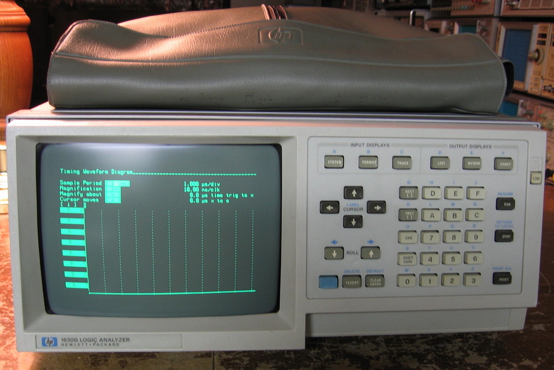
HP 1630G: 65 channel state/timing logic analyzer. 25 MHz state analysis and 8 channels of 100 MHz timing analysis. Very simple to operate and very useful to quickly diagnose faulty logic chips. I use this mostly in timing mode since I don't have much call for state machine analyses. (OM) Grade: B+
I first bought an HP 1630D. That unit had problems in state mode (worked OK in timing mode). It took several weeks to trace it down to a single faulty ECL chip among hundreds and hundreds. In the meantime, I bought the 1630G with the intention of swapping boards to help isolate the problem. After I fixed the first 1630D unit, I sold it to a friend for what I paid for it and kept the 1630G.
Postscript: Preemptively replaced the 0.022 uF Rifa Y-capacitor on the main P/S board with a non-Rifa 0.01 uF Y-capacitor.
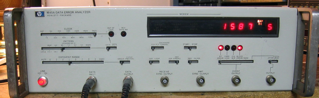
HP 1645A: The HP 1645A is basically a modem tester capable of measuring a variety of bit error statistics. Think of it as a transmitter, receiver and a correlator to count the errors between them. It is a junior version of the HP 3764A (which tests at 139 MHz) and only goes up to 9600 bps. Seeing as I don't have any modems to test, all I can do is run the internal self-test which purposely inserts errors. (OM) Grade: B-
And I quote myself from the General Repair Notes section below, "mechanical failures out-number electrical failures by 5-to-1." In this case, make that 6-to-0. When I received this glorious seven dollar piece, the printer connector on the rear panel had been smashed and all the wiring to the internal board shorted. The simplest solution was to remove the small daughterboard containing the wiring. Then when I went to check the line fuse, I noticed that the fuse cap was missing and the fuse holder itself was smashed. That was replaced with a new holder scavenged from a defunct HP 410C. Turning on the unit subsequently identified the main power switch as open, so that was also replaced by a switch from the HP 410C. Now the unit turned on, but the displays were erratic and the unit did not function properly. The front panel uses sliding switches that drag contacts across the board, just like the HP 8012B. These are problematic at best, so the entire front panel was dissected and thoroughly cleaned. Now the unit started to behave itself, but it would not receive a signal routed from the transmit to receive connector. I identified another daughterboard that was causing the problem and a simple reseating seemed to solve that problem. Finally, the exponent LED on the display was not working properly. When it was supposed to be 0, it read 8. When it was supposed to be 1, it read 9, All digits that were supposed to be >1 produced partial numbers on the LED. Looking at the schematic, it was easy to see what was wrong. There is a 1-2-4-8 decoder that drives the LED. Clearly the 8 digit line was stuck high. This accounts for the 0-8 and 1-9 behavior and made an illegal condition for inputs >1 (which would be 10 with the stuck bit). I was all ready to repair this the following morning - but when I turned the unit on, it had fixed itself. So that's 1) printer port, 2) fuse holder, 3) power switch, 4) front panel sliders, 5) transmit-receive signal and 6) exponent LED. Mechanical 6, electrical 0. I rest my case.
And I quote myself from the General Repair Notes section below, "mechanical failures out-number electrical failures by 5-to-1." In this case, make that 6-to-0. When I received this glorious seven dollar piece, the printer connector on the rear panel had been smashed and all the wiring to the internal board shorted. The simplest solution was to remove the small daughterboard containing the wiring. Then when I went to check the line fuse, I noticed that the fuse cap was missing and the fuse holder itself was smashed. That was replaced with a new holder scavenged from a defunct HP 410C. Turning on the unit subsequently identified the main power switch as open, so that was also replaced by a switch from the HP 410C. Now the unit turned on, but the displays were erratic and the unit did not function properly. The front panel uses sliding switches that drag contacts across the board, just like the HP 8012B. These are problematic at best, so the entire front panel was dissected and thoroughly cleaned. Now the unit started to behave itself, but it would not receive a signal routed from the transmit to receive connector. I identified another daughterboard that was causing the problem and a simple reseating seemed to solve that problem. Finally, the exponent LED on the display was not working properly. When it was supposed to be 0, it read 8. When it was supposed to be 1, it read 9, All digits that were supposed to be >1 produced partial numbers on the LED. Looking at the schematic, it was easy to see what was wrong. There is a 1-2-4-8 decoder that drives the LED. Clearly the 8 digit line was stuck high. This accounts for the 0-8 and 1-9 behavior and made an illegal condition for inputs >1 (which would be 10 with the stuck bit). I was all ready to repair this the following morning - but when I turned the unit on, it had fixed itself. So that's 1) printer port, 2) fuse holder, 3) power switch, 4) front panel sliders, 5) transmit-receive signal and 6) exponent LED. Mechanical 6, electrical 0. I rest my case.
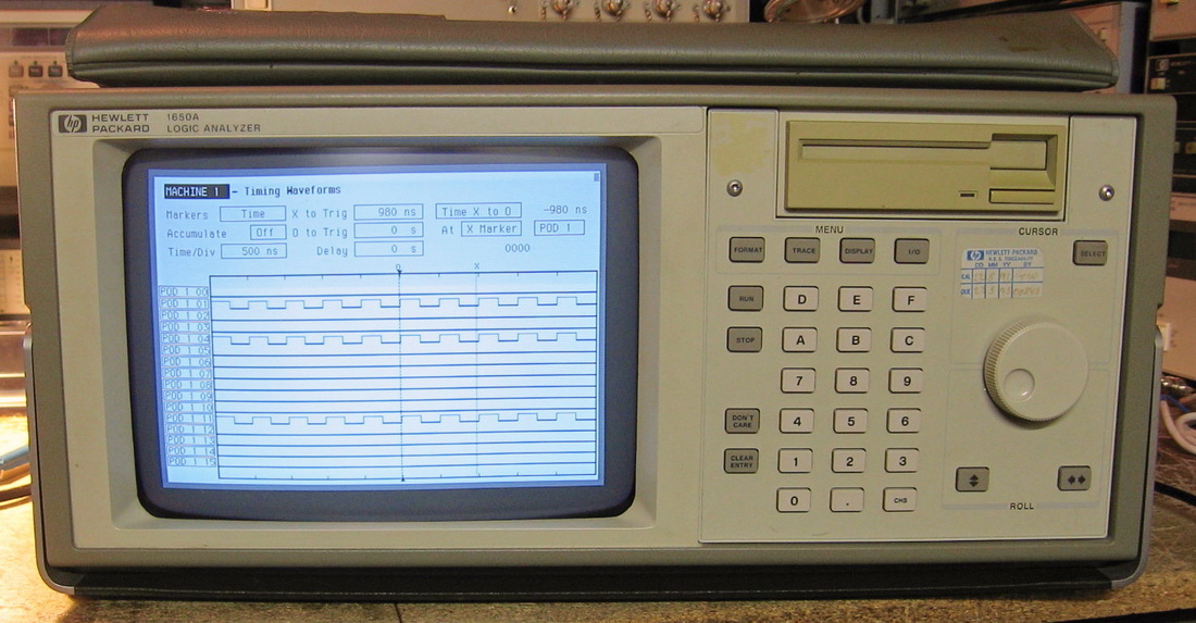
HP 1650A: 80 channel logic analyzer good in timing mode to 100 MHz (state mode to 25 MHz). I bought this for a few bucks in order to rip out the power supply to fix my HP 53310A Modulation Domain Analyzer. But I ended up building a new power supply for the 53310A so I was left with this piece. It was sans probes, but I used an old 40 connector IDE cable from a computer and the passive RC-compensated probes from my HP 16500A logic analyzer and it works fine. Fortunately the seller included the floppy for the operating system (which annoyingly has to be loaded at power-up). Easier to use than the 1630 series, but then that is because the amount of displayed information is also less. (PDF) Grade: B+
Notice the nice bright display in the photo? Even though I have rarely used this piece, the last time I did use it, the display was noticeably fainter and difficult to see at full brightness. I have an HP 53310A parts mule with a perfectly good CRT. The size is the same, the connections to the video board look the same, but the actual part number for the CRT is different. I surmised that the difference was that the 1650A's phosphor is bluish-white and the 53310A's phosphor is green. So I took a chance (and a couple of hours) and put the 53301A's CRT into the 1650A. Works like a champ - nice and bright. I prefer the bluish-white phosphor since the text is all done in inverse video. But it's not very desirable if one can't see it!
Notice the nice bright display in the photo? Even though I have rarely used this piece, the last time I did use it, the display was noticeably fainter and difficult to see at full brightness. I have an HP 53310A parts mule with a perfectly good CRT. The size is the same, the connections to the video board look the same, but the actual part number for the CRT is different. I surmised that the difference was that the 1650A's phosphor is bluish-white and the 53310A's phosphor is green. So I took a chance (and a couple of hours) and put the 53301A's CRT into the 1650A. Works like a champ - nice and bright. I prefer the bluish-white phosphor since the text is all done in inverse video. But it's not very desirable if one can't see it!
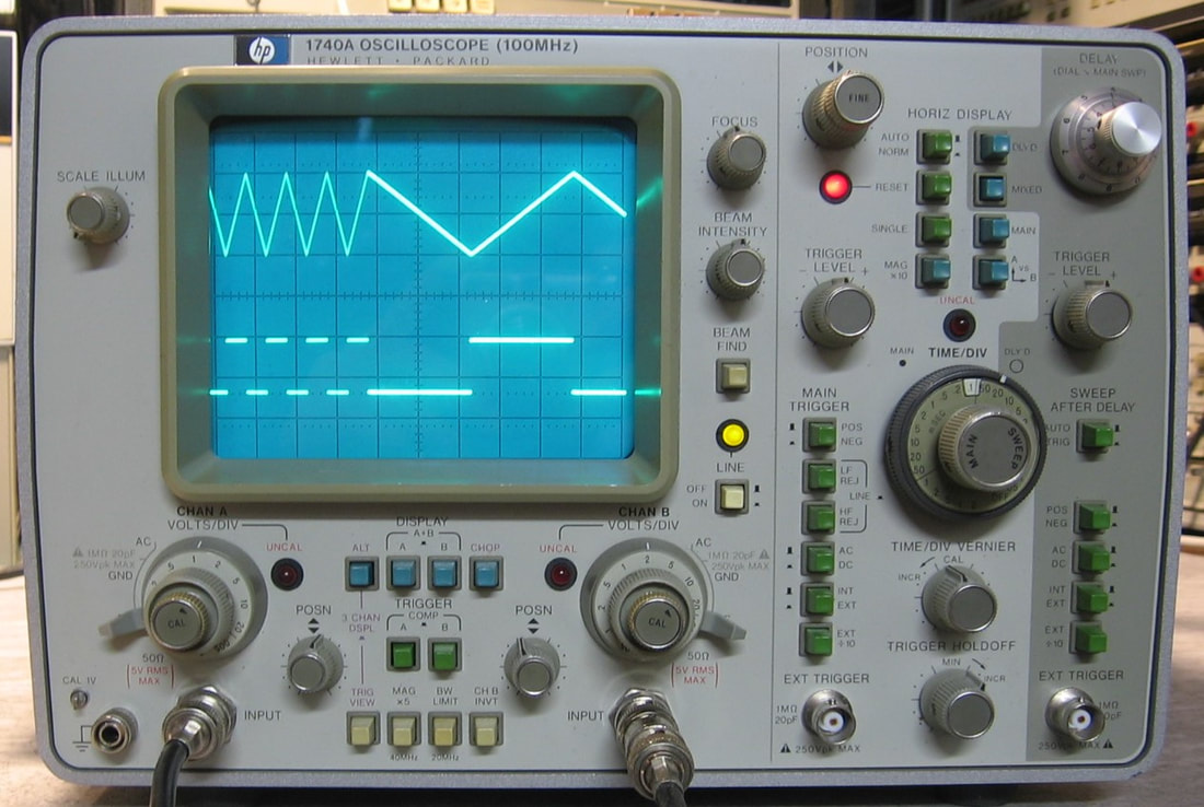
HP 1740A: 100 MHz oscilloscope. The HP 1720A oscilloscope was the very first piece of test equipment I ever bought on eBay, for $50 if I remember 20+ years ago (I've long since sold it), so it was only fitting that I buy an HP 1740A for good old times sake. The HP 1700 series of scopes were considered portable back in the late 1970's, but that is somewhat of a misnomer since they are large and weigh about around 30 lbs. I gather that the HP 1700 scopes gave the Tektronix 400 series some stiff competition back then. But I would rather repair and recalibrate the HP scopes any day over the Tektronix scopes. The 1740A is a dual timebase 100 MHz scope with most of the features one would want, including 50 ohm input coupling. (PDF) Grade: A-
When received, the power supplies all checked out OK, but there was only a small portion horizontally of the trace visible. It took me a while to realize that I was looking at the intensified portion of the trace and once I turned up the brightness, the main trace showed up! Silly me. On the other hand, unlike a lot of scopes, the intensified portion always shows up on the trace even if you are only using the main timebase/trace (there is an off setting however). Usually, you don't see the intensified portion unless you invoke the dual timebase modes. Nonetheless, I really could not find anything wrong with the unit except that the CRT was rotated about 10 degrees. That was easily fixed by loosening the clamp at the neck of the tube and rotating the tube back. I also disassembled, cleaned and regreased the main and delayed timebase rotary switch mechanisms. Also, when I took the covers off initially, a screw/locknut/washer fell out onto my table. It took me a while to figure out where it went (it holds a cable clamp on the side of the cover of the A-channel attenuator module). Finally, I ran through the calibration procedure and everything performed nicely. The previous owner really took exquisite care of the scope. There isn't a mark on it and it is one of the most cosmetically perfect pieces I've ever bought. My 1740A has chip date codes of 1984 and HP stopped selling them after 1985, so mine is a very late model. Fortunately, the free pdf service manual, for models with a 1976 design date, only disagreed slightly with what I have.
When received, the power supplies all checked out OK, but there was only a small portion horizontally of the trace visible. It took me a while to realize that I was looking at the intensified portion of the trace and once I turned up the brightness, the main trace showed up! Silly me. On the other hand, unlike a lot of scopes, the intensified portion always shows up on the trace even if you are only using the main timebase/trace (there is an off setting however). Usually, you don't see the intensified portion unless you invoke the dual timebase modes. Nonetheless, I really could not find anything wrong with the unit except that the CRT was rotated about 10 degrees. That was easily fixed by loosening the clamp at the neck of the tube and rotating the tube back. I also disassembled, cleaned and regreased the main and delayed timebase rotary switch mechanisms. Also, when I took the covers off initially, a screw/locknut/washer fell out onto my table. It took me a while to figure out where it went (it holds a cable clamp on the side of the cover of the A-channel attenuator module). Finally, I ran through the calibration procedure and everything performed nicely. The previous owner really took exquisite care of the scope. There isn't a mark on it and it is one of the most cosmetically perfect pieces I've ever bought. My 1740A has chip date codes of 1984 and HP stopped selling them after 1985, so mine is a very late model. Fortunately, the free pdf service manual, for models with a 1976 design date, only disagreed slightly with what I have.
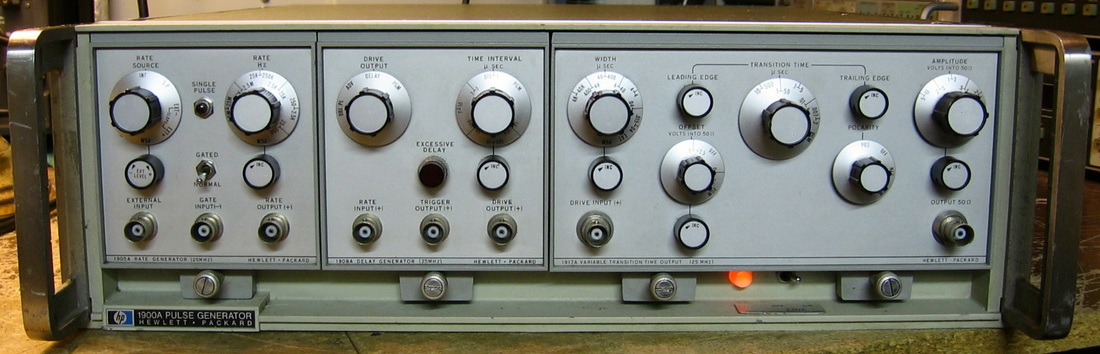
HP 1900A: The HP 1900A mainframe is a close cousin of the HP 1901A (listed below) differing only in the capabilities of the power supply. This unit is populated with the 1905A rate generator, 1908A delay generator and 1917A output shaper/amplifier. The 1905A/1908A are the precursors to the 1906A/1909A in my 1901A mainframe and are better suited in my opinion because they only go up to the 25 MHz rating of the output amplifier. Besides, the 1905A doesn't have that pesky tunnel diode. (PDF) Grade: B-
Not much to do here. The only casualty was a missing rear panel fuse holder cap (and thus the fuse). But this fuse only controls the portion of the 1900A P/S that my plug-ins don't require, so the only ill effect was an unlit front panel neon power light. As far as I can tell, it's the original NE-2 bulb as is every other part in the unit. Remarkable that no rework has been done in the 40+ years of its life. Original mid-70s catalog price: about $2,000. My price: $4.99 + shipping.
Not much to do here. The only casualty was a missing rear panel fuse holder cap (and thus the fuse). But this fuse only controls the portion of the 1900A P/S that my plug-ins don't require, so the only ill effect was an unlit front panel neon power light. As far as I can tell, it's the original NE-2 bulb as is every other part in the unit. Remarkable that no rework has been done in the 40+ years of its life. Original mid-70s catalog price: about $2,000. My price: $4.99 + shipping.
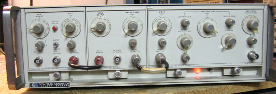
HP 1901A: The HP 1901A is a mainframe containing a power supply and room for four plug-ins. Mine is populated with a 1906A 125 MHz rate generator, a 1909A 125 MHz delay generator and a double width 1917A 25 MHz output shaper/amplifier. If you've read carefully, you will notice that the output unit only goes to 25 MHz, yet the two plug-ins feeding the output go to 125 MHz. So guess what happens? That's right, the complete system is merely a 25 MHz pulse generator. Nonetheless, it does offer pretty good control of pulse width, rise times, DC offsets, amplitudes, etc. (OM/PDF) Grade: C+
When I received this unit, everything seemed to work except the single pulse button on the 1906A rate generator. An inspection showed a massive amount of previous repair work on all three units, so I was a bit suspect. The rate generator circuit is based entirely on a single 20 ma tunnel diode which looked like it was previously replaced. In the process of trying to diagnose the faulty single pulse control, I must have done something really bad, because the tunnel diode went open and the entire 1906A ground to a halt. Now, the chances of getting another 20 ma tunnel diode are about the same as the chances that President Obama fixes the economy. But I did have a 10 ma tunnel diode (with a similar 500 mV swing) in a defunct Tektronix 7000-series plug-in. Of course, trying to switch a 10 ma tunnel diode with 20 ma isn't a good thing since you are off of the desired hysteresis curve. So I changed a bunch of resistors in the 1906A and re-biased everything down to 10 ma. That restored the 1906A - except, you guessed it, the single pulse circuitry still didn't work! After a few days of probing around, the problem seemed to be what HP called a "differential delay" circuit, which is simply a differential pair of transistors with a 1 nsec delay between the bases. This delay is accommodated by a long trace on the board. I tried replacing both the transistors, but in simple terms, it just looked like the delay wasn't long enough. So I cut the delay trace and soldered in another one foot of wire. Not particularly a good solution, because my wire can't be close enough to the board to act against the ground plane on the other side of the board. But good enough, since my single pulse now works and everything else seems to be OK. Well, almost everything else. If you are very careful and turn the pulse width down to the minimum on certain ranges, you get a double pulse out of the thing. But if you switch the rate generator to the next highest range, and throttle back on the frequency vernier, you can get the same rate and pulse width without the double pulse. I'll simply have to live with it.
When I received this unit, everything seemed to work except the single pulse button on the 1906A rate generator. An inspection showed a massive amount of previous repair work on all three units, so I was a bit suspect. The rate generator circuit is based entirely on a single 20 ma tunnel diode which looked like it was previously replaced. In the process of trying to diagnose the faulty single pulse control, I must have done something really bad, because the tunnel diode went open and the entire 1906A ground to a halt. Now, the chances of getting another 20 ma tunnel diode are about the same as the chances that President Obama fixes the economy. But I did have a 10 ma tunnel diode (with a similar 500 mV swing) in a defunct Tektronix 7000-series plug-in. Of course, trying to switch a 10 ma tunnel diode with 20 ma isn't a good thing since you are off of the desired hysteresis curve. So I changed a bunch of resistors in the 1906A and re-biased everything down to 10 ma. That restored the 1906A - except, you guessed it, the single pulse circuitry still didn't work! After a few days of probing around, the problem seemed to be what HP called a "differential delay" circuit, which is simply a differential pair of transistors with a 1 nsec delay between the bases. This delay is accommodated by a long trace on the board. I tried replacing both the transistors, but in simple terms, it just looked like the delay wasn't long enough. So I cut the delay trace and soldered in another one foot of wire. Not particularly a good solution, because my wire can't be close enough to the board to act against the ground plane on the other side of the board. But good enough, since my single pulse now works and everything else seems to be OK. Well, almost everything else. If you are very careful and turn the pulse width down to the minimum on certain ranges, you get a double pulse out of the thing. But if you switch the rate generator to the next highest range, and throttle back on the frequency vernier, you can get the same rate and pulse width without the double pulse. I'll simply have to live with it.
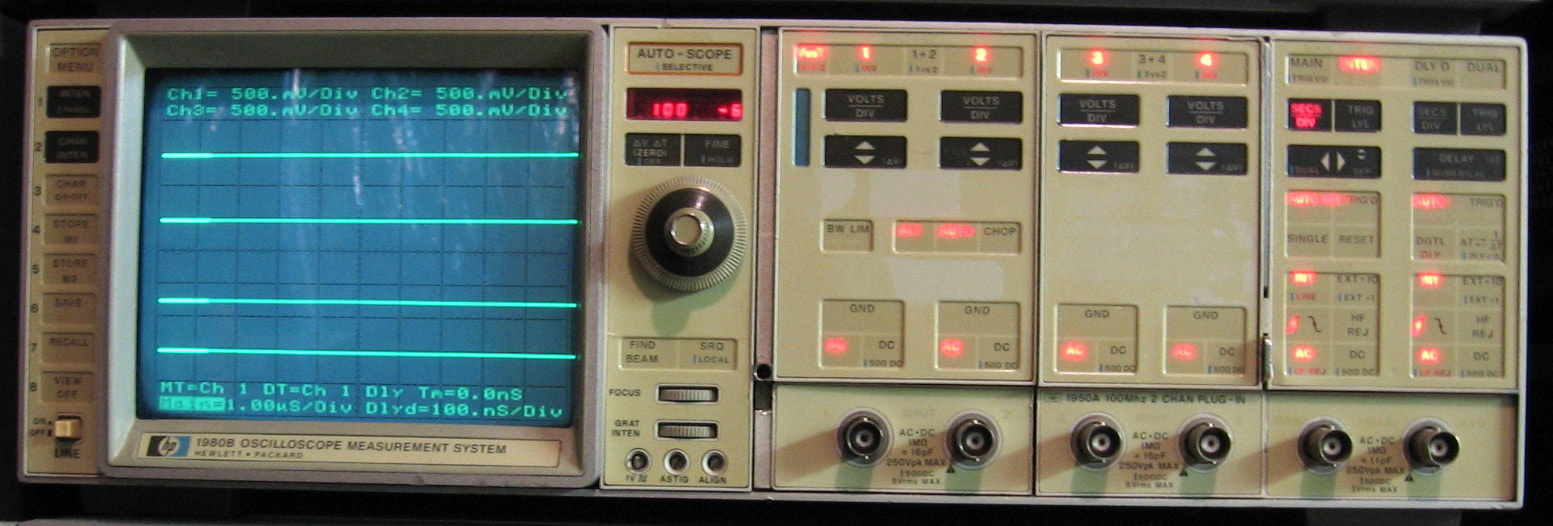
HP 1980B: Four channel 100 MHz oscilloscope, the first uP-based scope HP (or anyone else) built. This is basically an analog oscilloscope, but all the controls are run through a uP which then sets the hardware. The uP also permits GPIB communication to and from the machine and would allow automated measurements as part of a test fixture. The digital control also allows the scope to have an "autoset" button that examines the waveform and selects the optimal voltage and timebase settings. As an analog scope, it's nothing particularly noteworthy and the bandwidth certainly wasn't state-of-the-art at the time. Has the optional HP 19860A rudimentary waveform storage function (~500 points). One has to get used to this style of scope where a single knob controls all parameters. This "feature" was repeated on later HP scopes like my HP 54112D. I don't like it! Once again, my theorem which states that "HP = spectrum analyzer and Tektronix = oscilloscope," is proven out. Some of the internal HP documents from the 1970s and 1980s bemoan the fact that HP was desperate to catch up to Tektronix in the oscilloscope market. I'm not sure they ever did (although some of them that they built after 2010 aren't too bad). (OM) Grade: B+
When received, most of the light bulbs behind the front panel were toast, so I meticulously replaced about 90 of them with red LEDs. The channel 1&2 vertical preamp hybrid also required reseating. A while later, the thing acted up and the problem was a leaking timing capacitor in the horizontal circuit.
Postcript: Turned on the HP 1980B after about five years and all hell broke loose. Nothing seemed to work right and the thing threw cal error after cal error. The calibration of the 1980B is all done via software and it was throwing four (hardware) errors for the channel balance/baseline cal procedure and the remaining calibrations, although passed, seemed highly problematic (I had to often turn the adjustment knob many, many turns, which was clearly wrong). After a weekend of cleaning and reseating the many hybrids, all of which use troublesome elastomeric connectors, I have the thing 99% functional now. It go so bad at one point, that I got disgusted and moved this entry into the "It's dead, Jim" section below. But I put it back into the main web page since it is perfectly usable now. The 1% that doesn't work right is the baseline which shifts as a function of the V/div setting. Since this happens on all four channels, across two separate vertical preamp hybrids, I have to figure out what is common to all of them. The 600 page service manual is of no particular help, but maybe I will get lucky someday. Given my 11 other scopes, I really have no intention of ever using this thing, so I'm in no hurry.
Postscript^2: Well, of course I'm in a hurry. One of the hybrid ICs with the elastomeric connectors that I didn't pay too much attention to was the trigger IC, especially since one wouldn't think this would have any effect on the vertical preamp balance/baseline (now that I think of it, HP must have used the trigger level as an easy way to figure out input voltage levels). But after cleaning the trigger hybrid, the balance calibration passed, the remaining calibration of the unit was MUCH easier, and everything now works flawlessly. Although there are warnings in the manual about clean-handling the elastomeric connectors (they tell you to wear cotton or latex gloves), I was so frustrated that I ended up using 220 grit sandpaper wetted with tuner cleaner. So much for their warning... However, the eslastomeric connectors are also used in the front panel and ultimately this scope will prove to be a maintenance nightmare (unless I can find a cheap replacement source for the connectors).
Postscript^3: Many years later the scope started behaving badly. The chief symptom was that the text was scrambled and randomly flashing all over the screen. You can select "characters off" from the front panel, but the random characters remained (and they chop the signal trace also). Moreover, the 1980B would randomly change the character intensity, randomly lock-up, randomly not boot, etc. About four days of debug led to the conclusion that the two SRAM chips, A4U32 and A4U33, were bad. These chips are primarily used by the video controller to store the characters put on the screen, but the main microprocessor also puts some stack information in these two SRAMS. So if these SRAMs are bad, all kinds of bad things can happen. A new set of SRAMs seemed to fix everything, but the calibration was way off since I had already cleared out the other battery-backed-up RAM chips holding the cal constants. I've gone through the cal procedure a few times now and the 1980B seems to be relatively intact.
Postscript^4: Right after I reworked the uP board and installed the two SRAMs, I noticed that the digitizer option (HP 19860A) no longer worked. Dropped a few bucks on the service manual and it looked like the digitizer boards were operating properly. Basically, the scope tries to digitize, then hangs. Moreover, when it starts to digitize, it throws the scope into the intensified mode. And the intensified mode no longer works correctly anyway. And then channel #4 started to act funny on certain V/div ranges. What a complete mess. I dissected channel #4's attenuator and cleaned the contacts; that restored the channel's functionality. Why the intensified mode no longer worked was eventually traced to a set of ECL chips whose logic levels (particularly the low level) was not correct. And this was caused by me inadvertently when I went through the adjustment procedure days earlier. Long story short - there is a pot that, among other things, defines the ECL-low voltage. Once I set the pot correctly, the intensified function worked correctly. Moreover, the digitizer now worked perfectly. Amazing what happens when the logic levels are correct! This one taunted me for about 10 days until I got it all working.
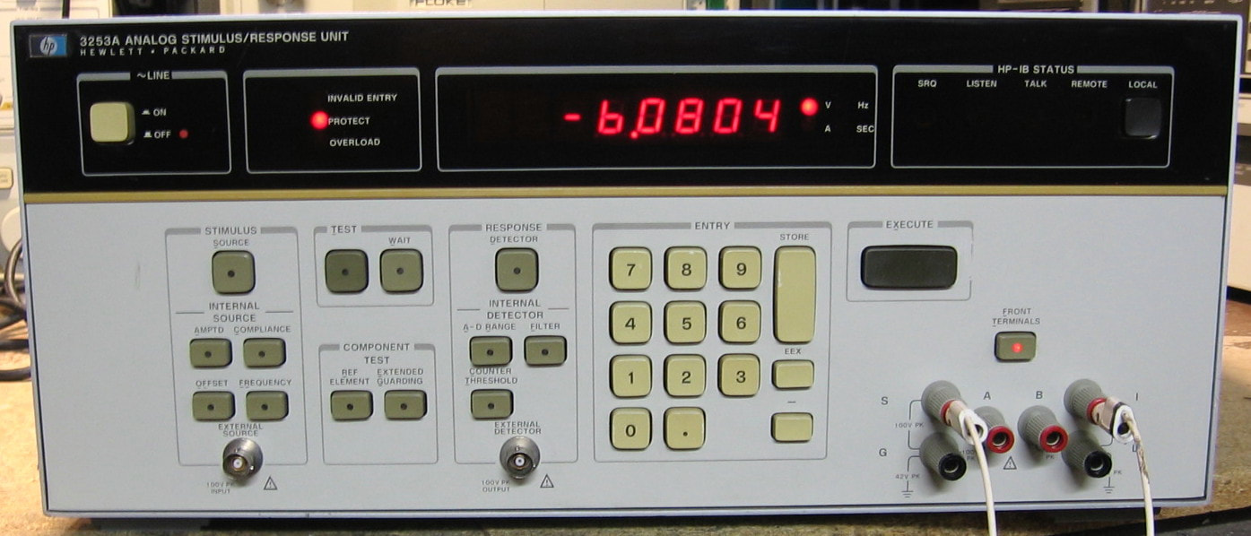
HP 3253A: Analog Stimulus Unit. This rather bizarre piece is a component of the HP 3060A board test system, which itself was a monster system sold by HP to board manufacturers. The 3060A (and later 3065A, 3070A) contained both an analog stimulus unit and a digital stimulus unit hooked (via HPIB) to a computer. The stimulus units were designed to run cables from their back panels to a special "board of nails" text fixture. However, it is possible to run the 3253A as a self-contained piece from the front panel using the front panel jacks - and that's what I've got. As to the 3253A, I'll try to summarize things in a few hundred words. One can view the 3253A as having the following: 1) a source generator which can be DC or a basic function generator, with both voltage and current settings; 2) a range resistor (1, 10, 100, …, 1M); 3) an op-amp; and 4) a detector, which can be an AC voltmeter, DC voltmeter or a frequency counter. The idea is to configure the 3253A to measure something across the front panel jacks. Now it is not quite that easy, however. For instance, suppose you put a 2K resistor between the S and I jacks. You set the test number to 1, set the source to 1 VDC, set the range resistor to 1K, and set the detector to a 5-1/2 digit DC voltmeter. This configures things so that the source is going through the range resistor to the feedback terminal of the op-amp, with the "unknown" 2K resistor going between the op-amp output and the same feedback terminal. Nominally then you would read -0.5 volts on the display. In other words, an unknown resistance equals -S*R/V, where S is the source voltage, R is the reference resistor and the V is the displayed voltage. Clear as mud? I thought so. The 3253A is configured with about 15 pre-arranged tests, but I'm sure you could dream up some more. For instance, test #4 is a diode test and the photo shows the 3253A measuring a cheap nominal 6.2V Zener (remember, the voltage will appear negative due to the inverting op-amp). Having said all of this, one has to realize that this is not a precision piece. In other words, you wouldn't use the source as an accurate waveform generator, nor the detector as an accurate voltmeter. But I guess for an automated board tester, HP figured it was good enough. And it is built with typical HP overkill - a massive 50 lbs including separate power supplies for the source and detector circuitry. HP didn't skimp on parts either. My favorite is the dozen or so mercury reed relays with a "warning - Hg" stamped on their cases. Finally, I was only able to locate a partial operation manual. With over 40 adjustments inside, I sure would like the cal procedure. I'll tentatively give it a yawning grade - if I ever get the service manual some day, I'll bump the grade up. (---) Grade: B
When received, everything seemed to work. Which is good because without a service manual, there's no chance. The front panel was quite worn with a lot of buttons not clicking. I dissected the front panel and found two leaf springs missing and a bunch dislodged. Everything was put back in order.
When received, everything seemed to work. Which is good because without a service manual, there's no chance. The front panel was quite worn with a lot of buttons not clicking. I dissected the front panel and found two leaf springs missing and a bunch dislodged. Everything was put back in order.
HP On-Off Switch Bonus Rant: It has long been my suspicion that HP engineers participated in a company-wide inside joke to make sure that they varied their on-off switches as much as possible. How else can you explain the fact that the look and feel of most of their pieces are identical (at least across common decades) with the exception of the on-off switches? Not convinced? Scroll down to the "Z" section near the bottom of this web page. Well, the 3253A takes this lunacy to a whole new level. Look carefully at the upper left corner of the picture - see the red dot next to the "OFF" text? That seems kind of strange, to put a red LED next to the word "off." But it's not an LED, rather it is a painted red dot. And why is it there? Because there is also a red dot on the top of the actual power button. A red dot that is visible only when the button is out, i.e., the unit is off. But unless you are standing up and looking down at the unit, you can't see it. All the painted red dot on the front panel does is confuse the user into thinking the unit has been left powered on. I mean, really, whoever approved this scheme in the HP design review for the 3253A should be forced to track down every one of these units in the field and paint over the red dot with some black paint.
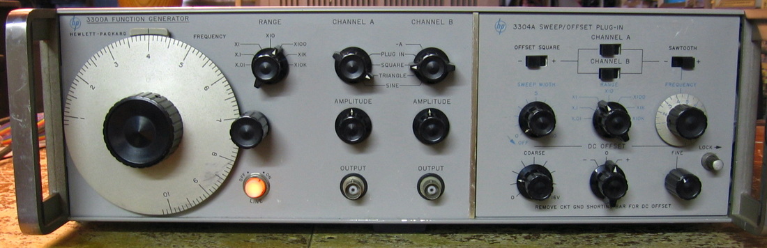
HP 3300A: Two channel 100 kHz function generator. Does sine, square, triangle, sweeps. Open circuit voltage to 35V, but very imprecise control of amplitude. Having two channels (phase locked) is very nice. Too bad HP retreated from two channel designs for the most part ever since. (PDF) Grade: B-
Had one open resistor and one bad transistor (2N3053 was replaced with 2N2102).
Postscript: Turned this thing on after a few years and it failed to oscillate. Part of the -20V supply is a pair of transistors forming a differential amplifier. These transistors are contained in the 3300A's oven module. When I opened up the module, I found the two transistors with leads that had corroded into dust. A pair of 2N3906s fixed the problem.
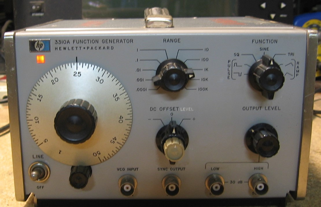
HP 3310A: 5 MHz function generator introduced in 1970 and covering 10 decades of frequency with 15 Vp-p into a 50 ohm load. Does sine, triangle, square, pulse and ramp functions. A pretty capable little piece marred only by its dependence on (now unobtainable) tunnel diodes. (PDF) Grade: B+
This was advertised as "doesn't power up despite trying a new fuse." And the simple answer was a broken front panel power switch. Fortunately the rest of the piece was intact, despite a few transistors having been replaced by a previous owner, and the alignment went smoothly (it was pretty much spot-on anyway).
This was advertised as "doesn't power up despite trying a new fuse." And the simple answer was a broken front panel power switch. Fortunately the rest of the piece was intact, despite a few transistors having been replaced by a previous owner, and the alignment went smoothly (it was pretty much spot-on anyway).
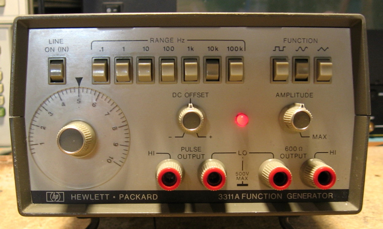
HP 3311A: 1 MHz function generator designed by HP to compete in the low end market. Sold for less than $300 when introduced, HP really didn't know how to make things cheaply. But this piece does what it advertises: sine, square, triangle and pulse waveforms with amplitude and DC offset control. Probably designed for the audio crowd, the output impedance is 600 ohms. The distortion is only rated to <-30 dBc, but I'm getting about -45 dBc on the sine waves. (PDF) Grade: B
This was only $30 so how could I resist adding it to my existing collection of HP function generators: 3300A, 3312A, 3314A, 3320A, 3324A, 3325A, 3325B, and 3326A. But seriously, it was advertised as broken and I needed a good hour of entertainment. The buttons needed a squirt of cleaner which fixed almost all ills. But I was getting no output from the pulse jacks and a quick glance inside showed a 74LS00 with a nice bubble in the middle. A new 74LS00 fixed that.
This was only $30 so how could I resist adding it to my existing collection of HP function generators: 3300A, 3312A, 3314A, 3320A, 3324A, 3325A, 3325B, and 3326A. But seriously, it was advertised as broken and I needed a good hour of entertainment. The buttons needed a squirt of cleaner which fixed almost all ills. But I was getting no output from the pulse jacks and a quick glance inside showed a 74LS00 with a nice bubble in the middle. A new 74LS00 fixed that.
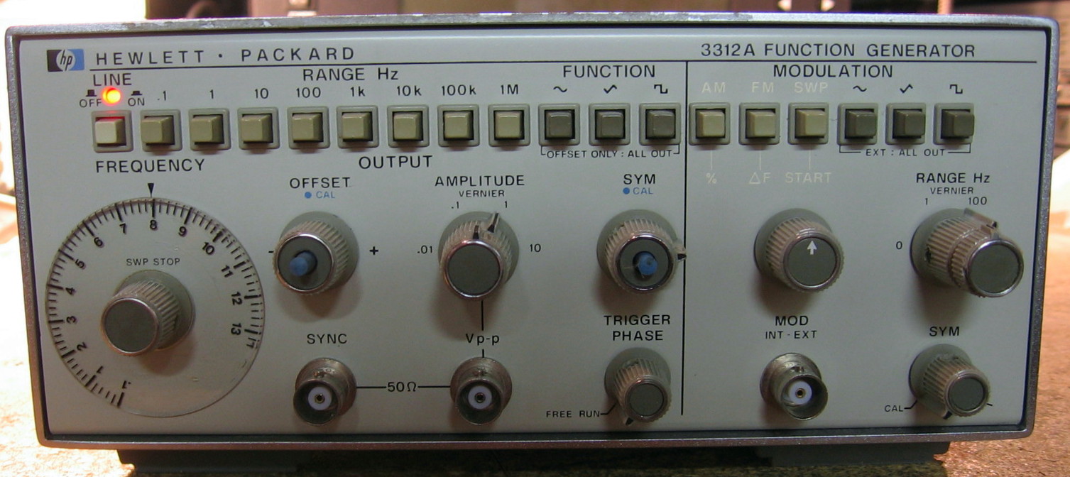
HP 3312A: 13 MHz function generator with auxiliary modulation generator. The 3312A was the last true analog function generator that HP produced. The architecture is the very familiar current generators charging/discharging a capacitor to produce a triangle waveform, and a diode network to do the sine shaping. No pesky digital circuitry to get in the way. Unlike many of these basic function generators (which are still being produced today by Instek, Tenma, BK Precision, etc.), this one goes up to 13 MHz. What also sets it apart is that it contains a second 10 kHz function generator that can be used to AM/FM/gate modulate the primary signal. The specs are not particularly noteworthy (for example, 5% dial accuracy, 0.5% THD) and, of course, you cannot precisely set the various parameters solely by looking at the front panel - you need external equipment like counters and AC voltmeters to set it to specific values. The build quality is a bit puzzling, however, containing a mix of methods to achieve board interconnects, and some of the switch arrangements are very cumbersome. Deserves a solid grade of "B" for "Boring" but I will bump it up a notch because of the auxiliary generator. (PDF) Grade: B+
Advertised as not powering up, I picked this unit up for $40. That's probably a bit high, but I hadn't bought anything in a while and it is, after all, a welcome addition to my HP collection. Upon receipt, the thing powered up just fine and all the P/S voltages checked out OK. The auxiliary generator seemed to function, but I got no output from the main generator. I should have done a very careful visual inspection first, not simply march my way with a scope through the signal path, because I would have spotted several problems immediately. First of all, there were three unsoldered wires flapping in the breeze. Second, the previous repairman must have tried to pull the front panel without noticing what needed to first be unsoldered, because one of the wires actually ripped off a piece of a wafer on one of the rotary switches. Third, when he did pull the front panel, he ripped the power LED to pieces. Fourth, one of the pushbutton switches was evidently removed and then reinstalled without soldering it. Plus, he lifted off one of traces going to the switch. And finally, the offset cal pushbutton switch was not latching properly (the offset control was where the three unsoldered wires should go). Anyway, everything was put back together with the help of epoxy and the unit calibrated nicely (it was way off, not surprising given the previous owner's record).
Advertised as not powering up, I picked this unit up for $40. That's probably a bit high, but I hadn't bought anything in a while and it is, after all, a welcome addition to my HP collection. Upon receipt, the thing powered up just fine and all the P/S voltages checked out OK. The auxiliary generator seemed to function, but I got no output from the main generator. I should have done a very careful visual inspection first, not simply march my way with a scope through the signal path, because I would have spotted several problems immediately. First of all, there were three unsoldered wires flapping in the breeze. Second, the previous repairman must have tried to pull the front panel without noticing what needed to first be unsoldered, because one of the wires actually ripped off a piece of a wafer on one of the rotary switches. Third, when he did pull the front panel, he ripped the power LED to pieces. Fourth, one of the pushbutton switches was evidently removed and then reinstalled without soldering it. Plus, he lifted off one of traces going to the switch. And finally, the offset cal pushbutton switch was not latching properly (the offset control was where the three unsoldered wires should go). Anyway, everything was put back together with the help of epoxy and the unit calibrated nicely (it was way off, not surprising given the previous owner's record).

HP 3314A: 20 MHz function generator, arbitrary waveform generator, the most versatile of the era. The arbitrary waveform generation setup is a royal pain. Basically you have control over the slope and duration from one point of the waveform to the next. It will also play a part of Beethoven's 9th Symphony if you hold down the right buttons when you power it up. I must have bid on a dozen of these before I finally won one. (PDF) Grade: A
Postscript: I came across another broken eBay HP 3314A which I managed to get for $50. This one, however, is the newer version distinguishable by the mushy, non-click front panel buttons and the rocker style on/off switch. The LED readout is also slightly different. See the repair details below, but, in short, I kept the newer unit and sold off the older 3314A for the same $50.
This is an interesting story. When received, the front panel needed rebuilding (new pushbutton switches salvaged from an HP 3437A). The signal output was not proper and the problem was traced to a defective HP custom hybrid IC (unobtainable of course). I rewired the circuitry around the hybrid and got the thing to work fine. But I sacrificed the ability to do anything other than 50% symmetry on waveforms. I then bought a second unit that seemed to work. I exchanged the front panels and pulled the HV option board out of the first unit. I kept this second unit and sold the first HP 3314A for $100 (about what I paid for it).
Postscript: The unit had been sporadically not turning on (other than the fan) for a while. A quick measurement of the P/S showed that the three intertwined supply voltages were way low. Well, HP decided to socket the three P/S pass transistors, and in a very un-HP-like fashion, used extremely cheap sockets. So the three transistors were pulled out, cleaned and reinserted. It's been OK ever since.
Postscript^2: I guess that "It's been OK ever since" is relative, since the P/S fault occurred again. This time I removed the sockets and soldered in the three pass transistors permanently. I'd like to see the fault happen now. I mean, do you feel lucky? Well do you punk?
Postscript^3: As described above, I bought the newer version 3314A which arrived in a "doesn't power-up" condition. Given the experience described above, the first thing I checked were the three pass transistor sockets. One of them had an obvious cracked solder joint and one of the other pins had absolutely no solder at all. Eureka, I thought. But alas, the 5V supply still didn't come up. It is a switching supply at a fixed ~32 kHz that varies the pulse width of the switch to do the regulation. Although I could see the 32 kHz pulses, the whole pulse stream seem to cut completely out at about a 30 Hz rate lowering my 5V down to about 1V. Turned out to be the electrolytic cap on the output. Even though the capacitance tested fine (actually a bit high), the ESR was about 1.5 ohms which is a lot for a high value cap. I've read that switchers can have problems unless low ESR capacitors are used and I guess this was a prime example. With the P/S fixed, the unit sprang to life. But all was not well as there were small, high frequency glitches at the top and bottom of the triangle wave output (and hence the sine and square since these are derived from the triangle). I exchanged the signal generation board (A1) with my other unit and the fault followed with the board. I spent numerous hours trying to quell the glitch but was ultimately unsuccessful. So I sold off the (now defective) older unit and kept the newer unit with the older unit's A1 board installed.
Postscript^4: The fan was starting to make a lot of noise so I replaced it with a less noisy version from the junkbox.
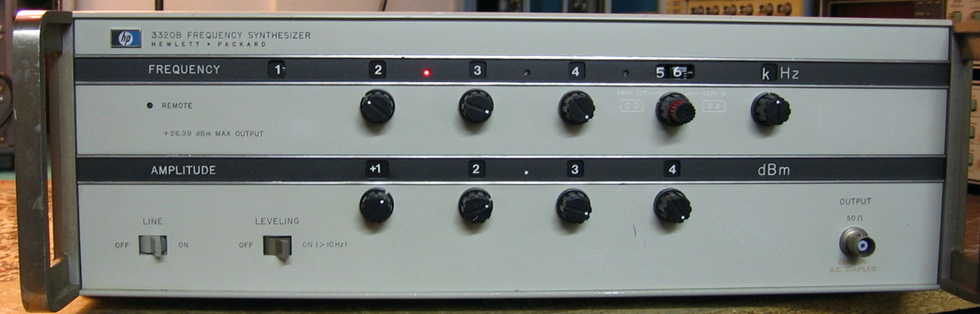
HP 3320B: 13 MHz synthesizer with very precise control of amplitude in dB. This is the lower cost version of the HP 3330B and shares much of the design. The one I have must have been a special telco order since it is set for 600 ohm output impedance; this option doesn't seem to have been offered to the general public. (PDF) Grade: A-
Other than the annoyance of a 600 ohm output, the only thing functionally wrong was the inability to correctly control the frequency in the third digit. This was traced to two 50 pin IDC edge connectors whose pins had permanently receded to the point of not making contact with the board. These two connectors were replaced and new (non-HP) knobs were also installed since many of the old knobs were missing and/or cracked. Finally, removal of one resistor on the output board, changing one resistor on the amplitude reference board, and reconfiguring several jumpers on the control board put the 3320B back to 50 ohms.
Other than the annoyance of a 600 ohm output, the only thing functionally wrong was the inability to correctly control the frequency in the third digit. This was traced to two 50 pin IDC edge connectors whose pins had permanently receded to the point of not making contact with the board. These two connectors were replaced and new (non-HP) knobs were also installed since many of the old knobs were missing and/or cracked. Finally, removal of one resistor on the output board, changing one resistor on the amplitude reference board, and reconfiguring several jumpers on the control board put the 3320B back to 50 ohms.

HP 3324A: 21 MHz function generator. While the HP 3325A (and successor, HP 3325B) were perfectly good function generators, HP decided to build a more "modern" version. Why, I'm not quite sure, but perhaps they managed to get the cost (and retail price) down. The general specs are not really any better than the 3325 series, but the 3324A is a little more capable in the sweep department. Very strange build quality containing both surface-mount and through-hole construction. And the knobology requires a little bit of thought. (PDF) Grade: B+
The eBay listing photo showed the front panel cracked off from it's mountings, but for $50 + shipping, I took a chance. Turns out that whoever dropped, smashed, kicked, beat, or drove over it with a truck, they managed to completely shatter the glass vacuum fluorescent display inside. The seller, however, couldn't care less despite my protestations. Funny thing is that the unit functionally is perfect. All the signal generation is spot on, but you just can't see what entries you are making. So I'm not going to include this piece in my "official count," but it is perfectly usable either blindly or with a GPIB connection. Also, I wasn't burned too badly, because the thing had a very nice OCXO that I pulled and made into a portable OCXO for use with any one of a dozen of my other pieces. Merely plug the OCXO assembly into AC, take the AC output coming off the portable OCXO and plug that into a piece of equipment's AC outlet, and run a BNC cable from the OCXO into the external 10 MHz input of the piece - voila, instant OCXO (see picture below). And, if I ever find a replacement display for the 3324A, I can always easily reinstall the oscillator board.
Postscript: After about a year, a unit came up for sale with a working display and a reasonable price. Although I only really needed the display, I took the whole unit (since shipping was free anyway). Reinstalled the OCXO that I had made into a standalone reference (see paragraph above) and now I have a fully functioning HP 3324A. I'm a bit disappointed nonetheless because the display is not very well designed - a lot of very small letters and symbols and a half-brightness/blinking scheme that is very difficult to see. I am very pleased however with how noise-free the output is at low voltages. Many of my other function generators are clean only down to about 10 mVrms; the 3324A looks clean at 1 mVrms.
Postscript^2: Preemptively replaced the Rifa 0.01 uF X- and two 0.0022 uF Y- caps with non-Rifa 0.01 uF X- and 0.0015 uF Y- caps.
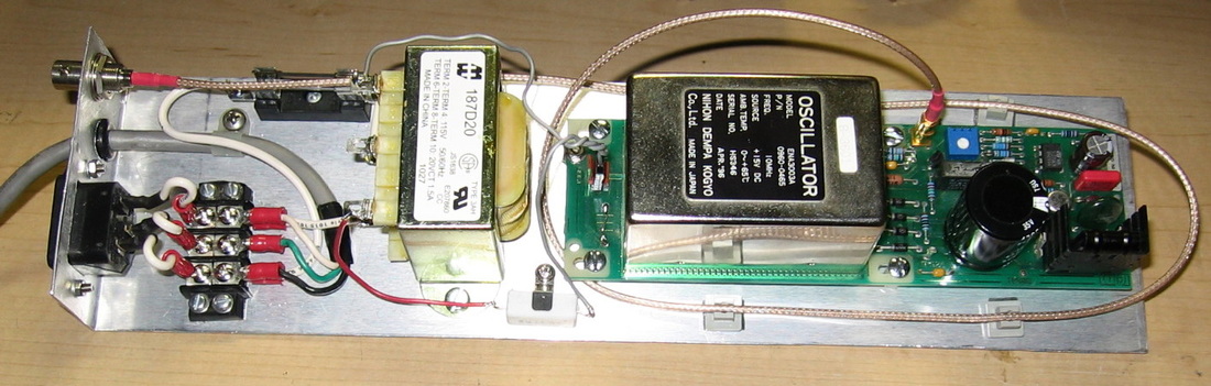

HP 3325A: Function generator 0-21 MHz (to 60 MHz at rear panel), basically a very good synthesizer with limited square, triangle and ramp functions, sweepable. Has high voltage option. This piece falls into the category of "misleading advertising" as far as I'm concerned. A 21 MHz function generator you say? Yes, if you want to generate sine waves. The other functions are limited to ~10 kHz. It also has an output attenuator that is done with relays that press contacts down on traces of the circuit board. These are problematic at best (although mine work fine after cleaning). (PDF) Grade: B+
Replaced open fuse in output circuit, freed stuck fan, replaced faulty pushbutton switch and faulty power switch, cleaned relays.
Replaced open fuse in output circuit, freed stuck fan, replaced faulty pushbutton switch and faulty power switch, cleaned relays.
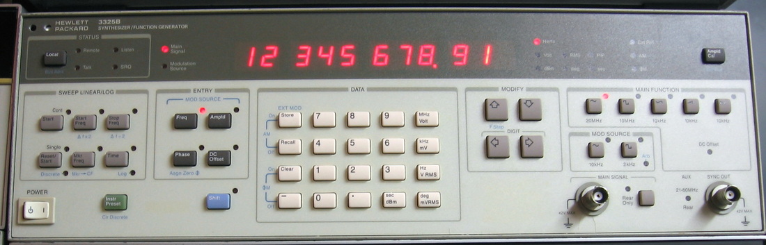
HP 3325B: Synthesizer/Function generator to 21 MHz. This was the follow-on to the "A" model and had a few minor functional improvements as well as a host of bug/reliability fixes. Unlike most function generators that start by producing a triangle and then deriving sine and square waves from that, the 3325 series starts with a fractional-N synthesizer implementation of a sine wave and then derives the square, triangle and ramp waveforms. That derivation is why, for instance, ramps can only get to 11 kHz, not 21 MHz. As far as new features, HP added a backup battery so settings can be saved, added an internal modulation source, upgraded the front panel to the spongy keys, and more. The reliability was enhanced with better connectors, attenuator relays and a lot of internal self-tests. What makes this a decent function generator is the 11 digit frequency resolution and very good amplitude accuracy. Unfortunately, I think it is somewhat of a flawed design (which is also shared by the HP 3336 series) because there are a fair amount of processor noise spikes and jitter (they switched to a different microprocessor/board in the B model). In the downloadable service manual, there is a section at the end that addresses numerous complaints by users. HP only gave a hand-waving explanation which vacillates between "it's not in the spec and supposed to work that way," and "your measurement equipment/technique is faulty." In other words, hook up the 3325 to a 25 MHz analog scope and everything looks great. Use some decent high bandwidth scopes, spectrum analyzers and counters, and you'll see what I'm talking about. Bottom line: don't try to crank the amplitude much lower than about 20 mVrms due to the +/-3 mV noise spikes that will falsely trigger a scope. Better yet, stick with the A model! (PDF) Grade: B (changed to a B+, see below)
Postscript: There are three 21-pin ribbon cables in the middle of the unit connecting various boards. As the repair notes below indicate, these are somewhat problematic. I thought I had "fixed" them, but the 3325B would often throw a FAIL 23 or FAIL 26 error upon startup, only to be cured by shaking the ribbon cables. I finally got fed up and replaced the one that seemed to be the culprit with a set of 21 jumper wires. This seems to also have calmed the excessive noise on the output down a bit, so I will bump up the grade from a B to a B+. Note: a post-mortem on the cable did indeed show several pins going up to kilo-ohms when the cable was flexed. The cable is like an ordinary insulation displacement cable, but it is a flat ribbon cable instead of the normal round wires. The way the pins pierce the flat ribbon is iffy at best.
Advertised as "has a transformer-like hum," that's what I heard when I plugged it in. Otherwise, it was dead. The hum was not coming from the transformer, but rather from the frozen fan. A replacement fan from the junkbox fixed that. But someone had gone where no man had gone before, because the previous repairman took the trouble to disconnect all three pass transistors and write "BAD" on top of all three main electrolytic capacitors. I pulled the caps (they weren't even soldered in) and they all tested marginally OK, so I put them back in, hooked up the pass transistors and fired the thing up. It powered up fine, all voltages were in spec, but the 3325B threw some DC offset calibration errors and the waveforms had big DC offsets and were clipped at the top. A couple of hours of fruitless marching through the troubleshooting procedures in the service manual, and I found the real culprit which was a bad ribbon cable between the processor board and the D/A board. After fixing that, I attemped the cal procedure which passed with exception of the frequency accuracy. The thing is supposed to be within 5 Hz at 1 MHz, and I was 34 Hz low. The adjustment pot, which supplies voltage to a varactor in the crystal oscillator circuitry, was already at the limit, so I bypassed that and put the maximum voltage I could find across the varactor. That moved it to 4 Hz low, which is in spec. The 30 MHz crystal had a big dent in it, like someone tried to "adjust" it with a pliers. Unfortunately, by bypassing the adjust circuitry, I give up the ability to lock it to an external reference. A short time later, I found a replacement oscillator board used on the A model for $20, bought that, and used the crystal from that board to get the frequency spot on and recover the ability to externally clock the unit. Finally, the three main electrolytic caps do run warm - about 120 deg F - which is not to my liking, so perhaps they were "BAD" after all. I replaced them with low impedance, high ripple caps and also replaced the three P/S pass transistors whose leads had been snapped off 1 mm from the case by the previous repairman.
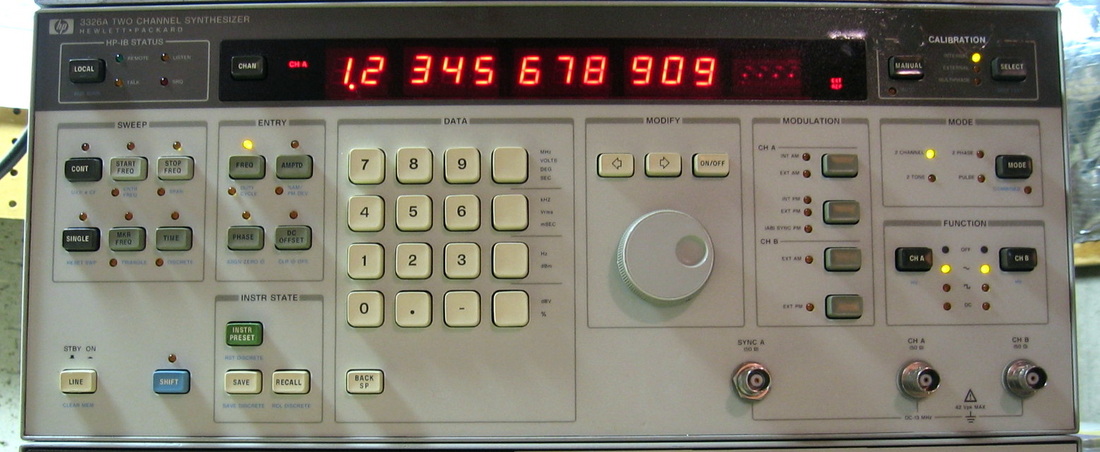
HP 3326A: Two channel function generator, 0 to 13 MHz. Basically two independently controlled HP 3325A synthesizer cores that can be phase locked, can modulate each other, etc. Semi-arbitrary control of sweep frequencies. One of the best HP produced. Exquisite control of all functions. My "go to" signal generator. ($CD) Grade: A
Gotta love pieces like this. When received, the A channel worked fine, the B channel was dead. Opened up the unit, saw a dangling coax connector, plugged it back in, presto!
Gotta love pieces like this. When received, the A channel worked fine, the B channel was dead. Opened up the unit, saw a dangling coax connector, plugged it back in, presto!
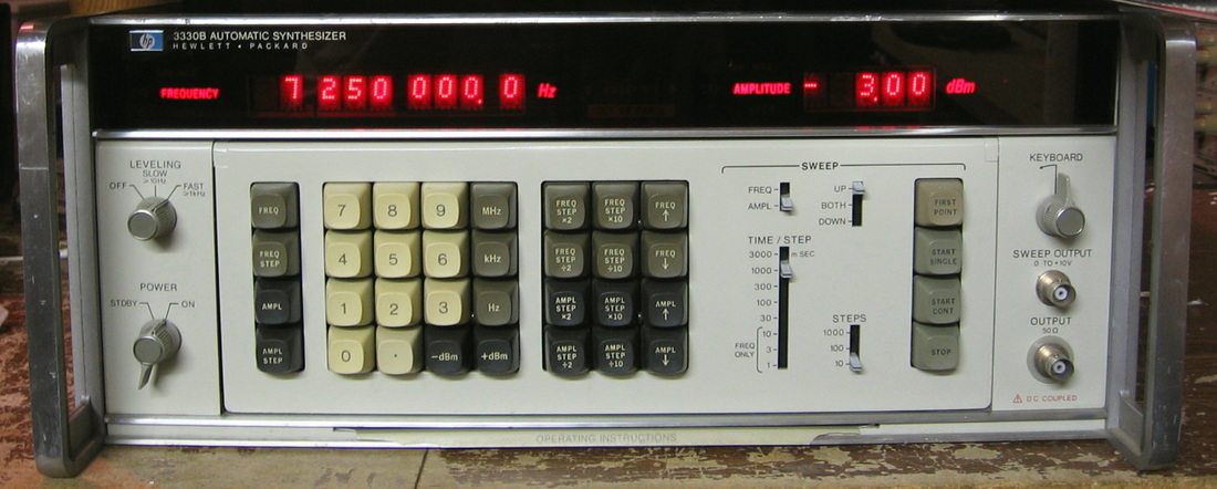
HP 3330B: 13 MHz sweeping synthesizer for use with 3570A tracking receiver as a network analyzer. Even though I have this permanently connected via rear panel jacks to the 3570A, it is a very good signal generator by itself. Has a front panel that rotates upwards for ease of use. (PDF) Grade: A-
Postscript: Turned the thing on after a year or so of being dormant and the amplitude display read "XX.00" (X = blank) and the frequency display's last four digits were stuck at zero. More perplexing, however, was that the amplitude entered on the keyboard produced the correct signal, whereas the signal frequency was always truncated to 1 kHz (000.0). Now this unit has a four board state-machine controller and the schematics say things like "troubleshooting of this assembly by board replacement is recommended because of the complexity of the circuit," and "because it is not feasible to troubleshoot to the component level, schematics have not been drawn." Besides, I would also need an 18 pin and 22 pin extender board or cable set. So I spent three hours pouring over the manual and came to the conclusion that the ONLY way 1) the amplitude is correct, 2) the frequency is truncated to 1 kHz multiples, 3) the amplitude display is incorrect and 4) the frequency display is correct except for the last four digits was a defective A5U17, a 74164 serial in parallel out shift register. I poured out my bucket of 74LS chips and found a 74LS164 on the 60th pick. Desoldered the old one, put in the new one (socketed of course) and.... C'mon, you know the answer. Go ahead, it won't hurt to admit it.
Postscript^2: Turned this on one day and the display went blank. The 15V P/S rail was reading about 4V and this was due to a short somewhere that was putting the P/S into current limiting mode. Hooked an ohmmeter across the rail and started pulling out boards until I found the offender. As usual, it was simply an electrolytic on the board that was shorted. After restoring the P/S, I noticed that the 3330B was way off in frequency and highly unstable. The diagnostic charts led me to the A15 sampler board and I did find a transistor that gave me a funky reading on my Peak DCA55 component analyzer. After a few transistor swaps and replacements, the thing was still behaving strangely. Little did I realize that I put one of the transistors back on the board backwards! Took me a few days of debug before I finally discovered it. But by then, I had turned every adjustment pot in this unit in desperation, so it was wildly out of calibration. Anyway, all is back to normal now and I am nursing my injury having shot myself in the foot on this one.
Postscript^3: Went looking for something to do, so I figured I would power up the 3330B for the first time in a year or two. Sure enough, the last two digits of the frequency and the last two digits of the amplitude were blank. I had seen something like this before, except the fault was with the last four digits of each display - see Postscript^1 above. The display is driven by a chain of 74164 shift registers, each seemingly handling two digits, and the Postscript^1 fix addressed the second to last one in the chain (hence, the last four digits). I figured this time it must be the same fault, but only with the last 74164 in the chain. Popped in a new one and all is well (again). Somewhat surprising that two of these chips failed - and they were Fairchild parts with a 1979 date code. Usually it is the National Semiconductor chips that are crap. But wait - Schlumberger bought Fairchild in 1979 and then sold it to National Semiconductor in 1987. So even though they aren't to blame, I will still condemn National Semiconductor just for fun.
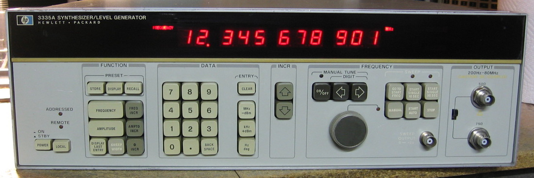
HP 3335A: 80 MHz Synthesizer/Level Generator: Like the HP 3336A/B/C, the HP 3335A was built for the telco industry and features extremely precise amplitude control. Whereas the 3336 series stops at 21 MHz, the 3335A goes to 81 MHz. It has some ability to sweep with limited control, but not as versatile as the 3336. Nor does it have any modulation capability like the 3336. Frequency resolution is 1 mHz and amplitude resolution is 0.01 dB, from 13 dBm to -87 dBm. And HP really means it! Phase locked to my best counter, it is a pleasure to set the 3335A 1 mHz from 10 MHz and watch the counter display 10.000 000 001. Similarly, using the most accurate power meter I have, the HP 3708A, I can set the 3335A anywhere from 0 dBm to -50 dBm and watch the 3708A display never be more than 0.03 dB off the setting. The output level accuracy is due to one of the best step attenuators that HP ever built. In fact, the 3335A was, and is today, the only HF/VHF generator with specs this good. And that is why many cal labs still use it. Has an OCXO, but it is not as good as the standard HP 10811 (which was offered as an option). My only gripe is that the knob can only be used to tune frequency. Amplitude has to be punched in on the keyboard. Finally, let me just remark that I have worked on over 100 HP pieces of this era and have seen pictures of the insides of probably 100 more. Never have I seen a piece quite like the 3335A. It's almost as if the engineers were designing their first piece of test equipment. Everything is done the hard way and thankfully, HP learned from this piece. (PDF) Grade: A-
These units usually go for around $300 on eBay, so I wasn't too upset to pay $100 for a broken one. The seller said the display flickers for a few seconds, then turns off. The listing picture showed a blank display with the "unlocked" and "unleveled" lights on. Well, the unlocked light is due to the oven in the oscillator not yet warmed up. And the listing picture of the back panel showed the level control switch set incorrectly to external. So those two problems were solved before I even got the piece. But upon receipt, the display flickered some random numerals, then went dark. A quick check of the -5, 15, 5 and -15 supplies showed (DC/AC): -5.3/0.3, 15.0/0.35, 4.58/0.16 and -13.8/0.18. Besides the excess ripple, the 4.58V was not enough to fire up the uP and hence the numbers were dark. I pulled the processor board and the voltages improved to -5.3/0.01, 15.1/0.66, 5.01/0.06, -14.35/0.27. But alas, I could see nothing overtly wrong with any of the parts on the uP board. Back it went, and I then pulled the connector to the step attenuator. The unit fired right up with a steady display and the voltages were pretty much what I had last observed. Since the step attenuator is controlled by the uP board, that told me that the step attenuator had the fault. So I pulled that unit out and dissected. The attenuator consists of a sealed compartment with a bunch of plungers sticking out. Above that sits four copies of the same control board, each controlling two solenoids that hit the plungers. Each board consists of a 74LS02, 8 transistors, 4 diodes and 4 resistors. Turns out that one of the control boards had a faulty 74LS02. Patting myself on the back for finding that so quickly, I reassembled and fired the unit up. Immediately, the 5V dropped to <4.7V and the display went dark. Back out came the attenuator and I spent an hour or so trying to isolate the bad control board. A lot of time was wasted because it finally dawned on me that they daisy-chained the 8V solenoid voltage through a connection on each board. So when I pulled the cable off of board #1, hoping to see the effect of the three remaining boards, they actually weren't getting any power. To make a long story short, made longer because at one point I hooked up some external voltage backwards and blew out 4 transistors and 4 diodes on one of the control boards, I concluded that the step attenuator was functioning. What appeared to be happening is that the solenoids use 8V to switch and that 8V is the main unregulated voltage that also inputs to the 5V regulator. The solenoids are magnetic-latching, but they each draw about 0.5A for a moment when they switch. So when the unit is first turned on, the step attenuator is commanded to switch to the default amplitude, the 8V unregulated line gets drawn down to about 7V, the 5V regulator fails to maintain the 5V, the processor halts, and the 8V is still loaded because the processor hasn't correctly ended the solenoid "pulse." I verified all of this by cutting the 8V wire to the attenuator and using an external P/S. The 3335A fired right up and everything worked if and only if I powered the attenuator externally. So that left the usual suspect - the main power supply. I had read on several forums that there are four 10 uF electrolytics (in the 15 and -15 volt regulator circuitry) that usually need replacing. I dissected the P/S and sure enough, 3 out of the 4 were toast. Again, patting myself on the back for finding the problem, I replaced all four and fired the unit up. Same damn thing - the uP voltage got dragged down and stopped. At this point, I was running out of options, but had a hunch that perhaps the NPN Darlington pass transistor didn't quite have a large enough beta to keep up the current draw when the collector dropped from 8V to 7V (although I don't quite see what the collector voltage has to do with anything). I didn't have a suitable transistor in the junkbox, but the same transistor is used in both the 5V and 15V regulators. So I simply swapped them. And that did the trick! The unit fired right up, the step attenuator clicked a few times, and the display was stable and correct. I thought at this point I was done - simply order a couple of NPN Darlingtons and replace the two for good measure. But then I took a look at the four P/S voltages only to find: -5.28/0.39, 14.98/2.0, 5.07/0.05 and -14.96/0.36. What, you say? 2.0V ripple on the 15V supply? That's the supply with the "iffy" 5V Darlington put into it. Moreover, the 2 VAC was a pretty nice sine wave at 350 kHz. It, unfortunately, manifested itself as 350 kHz sidebands on the sinewave output, at about -45 dBc. Moreover, at 1 kHz, the distortion was a terrible -42 dBc. Finally, I looked at the output filtering on the four regulators. There are four 50 uF capacitors all the way on the opposite side of the unit and two out of four (for the 15V and -15V) read only 1 nF. So all four were replaced. And now all four ripple voltages are <20 mV peak, the 350 kHz oscillation is gone and the 1 kHz distortion is -61 dBc. Now, one can make the argument that there was nothing wrong with the 5V Darlington. Perhaps it was simply loose in its socket or the pins were corroded. And perhaps the bad output caps were the cause of the bad 5V regulation. After all, the 5, -5 and -15V regulators work off of the 15V regulator. Oh well, I've already ordered two Darlingtons and in they will go when they arrive.
Postscript: The new Darlingtons went in without incident and the four ripple voltages are now <1 mV. I did a post-mortem on the old ones by hooking up a couple of power supplies to B-E and C-E and watching the collector current. With the same base current, the transistor that was originally in the 5V regulator and causing all of the grief drew about 1/10th the collector current of the other transistor. In technical terms, it simply lost its mojo.
Postscript^2: One day I had the 3335A hooked up to my HP 53310A modulation analyzer and saw the frequency wandering all over the place. After verifying that nothing was wrong with the 53310A, I did some more measurements and saw that at 1 MHz, the thing was reading 7 Hz high and wandering about 2 Hz in a few minutes. And this is with a supposed OCXO inside! I tried adjusting the OCXO but the adjustments could only get me from about 7 to 10 Hz high. When I looked at the current draw on the OCXO to determine when the heater was cycling on/off, it looked almost random to me. And even with a faulty heater circuit, that still doesn't explain the 10 ppm error. My conclusion? Toasted. So I pulled the OCXO out and replaced it with a very nice Vectron OCXO (with a trimmer for the electronic frequency adjustment and a 7805 regulator to supply the required 5V). Perfecto.
Postscript^3: Had the unit on for about an hour one day and suddenly the output went dead. All the controls seemed fine, the attenuator clicked, etc. Looking at the four P/S voltages, +/-15, +/-5, showed the -5V line at -1.6V. I had already replaced the two Darlington pass transistors on the +15 and +5V lines, so it would make sense that I would have problems some day on the negative side. Sure enough, the Darlington on the -5V line was toast. Replaced both the -15 and -5V transistors. I think the 3335A is inadequately cooled and the P/S basically cooks itself to death.
Postscript^4: The piece starts up frozen with no display. And that's because the microprocessor wasn't getting any clock. And that's because the master 40 MHz oscillator wasn't oscillating. And that's because the variable capacitor in the oscillators feedback circuitry needed adjustment. I guess components start to drift a little bit after 45 years. Still, once in a blue moon, the thing will not start due to this.
Postscript^5: I keep having to adjust the variable cap in the oscillator circuit (see Postscript^4) so there must be components on the board that are suffering from old age (crystal, varactor, caps in tank circuit, etc.). Rather than diagnose, I found it easier to buy a complete board for a few bucks from a seller in Israel. We'll see if and when I ever have to adjust this one.
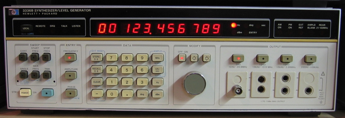
HP 3336B: Called by HP a "level generator," was built for telco and has 75 ohm output impedance (plus 124, 600, etc.). 0 - 21 MHz (60 MHz at rear) sine waves with 0.25 dB amplitude accuracy, sweepable. This was intended by HP to be used with the HP 3586B as a tracking generator. I use it simply as a very accurate signal generator for low frequencies. ($CD) Grade: A-
Not really a fix, but I did notice some distortion every time the thing switched across amplitude ranges. It required an adjustment to the analog multiplier chip. I also rewired the output for 50 ohms and replaced the Weco connector with a BNC jack.
Postscript: After several years of flawless behavior, the unit now just powers up, lights all the buttons and digits, and then sits there locked up. The problem was traced to a faulty 10V Zener that is used to supply voltage to the op-amps in the 5V regulator of the power supply.
Postscript^2: The problem with this unit (and the HP 3325A for that matter) is that when it sits dormant for a long time, the attenuator relays need to be removed, cleaned, toggled a few times and reassembled - then it works fine.
Postscript^3: The attenuator relays continue to be a weak point in the 3336B's design. The relays are called "Printac," but really should be called "Print Act Up". The bottom of the relays are open and consist of a set of fingers that sit over the traces on the attenuator board. Sounds good in theory, but the distance that the fingers protrude out the bottom and the pressure exerted by the clamp that holds the relay over the board have to be exactly right. And I mean exactly. Over time, the distance changes and that's pretty much all she wrote. After a couple of futile hours, I took off the clamps and soldered the relays to the board using a trial-and-error technique of adjusting the pressure. Seems to work OK now, but I'm guessing I will need to get a set of four DPDT latching relays and wire them up to the attenuator board.
Postscript^4: Went looking around for something to fix one day and thought I would power the 3336B up. Sure enough, although the 10 dB attenuators worked fine, the leveling loop that adjusts the amplitude was faulty. Indeed, changing the amplitude within a single 10 dB regime did nothing. The problem was fairly quickly traced to A4U23, an LM310 op-amp that was being used as a voltage follower out of the amplitude DAC circuitry. And this was another example of a failed National Semiconductor IC. Always suspect any National Semiconductor part. Always.
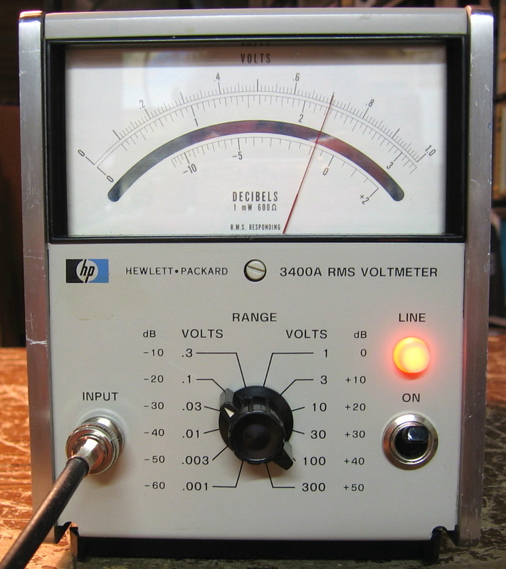
HP 3400A: 10 Hz - 10 MHz True RMS (thermocouple) AC Voltmeter. Shown here measuring 70 mV, 400 Hz (from Fluke 5200A AC Calibrator). Comparable to the Ballantine 323. If and when the thermocouple goes, it's toast. No replacements available. (PDF) Grade: A-
After several years, I noticed that the thing was way out of calibration - something like 20% off at 1 VAC. I couldn't get it to calibrate correctly, nor would the readings stay stable day to day. The problem mostly seemed to be coming from the input attenuation board. Fortunately I had a spare board so in it went. Seems OK now.
After several years, I noticed that the thing was way out of calibration - something like 20% off at 1 VAC. I couldn't get it to calibrate correctly, nor would the readings stay stable day to day. The problem mostly seemed to be coming from the input attenuation board. Fortunately I had a spare board so in it went. Seems OK now.
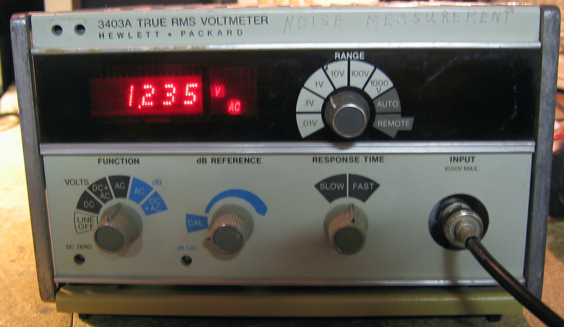
HP 3403A: True RMS AC voltmeter, good to 10 MHz with extension to 100 MHz on certain ranges. Accuracy in the 0.2% to 0.5% range. Mine has the dB display option and the auto-ranging option. Relatively slow update rate, but otherwise a reasonably good unit. (PDF) Grade: A-
The piece was advertised by the seller as "doesn't power up." But a close examination of the photos showed that the fuse holder cap was missing, so duh. It took 1) a new fuse holder, 2) a new bridge rectifier and 3) a new pass transistor to at least get the unit powered up. Then the last half of the rightmost digit was blank and that was traced to a corroded trace (from something that had previously been spilled on the unit years ago) on the display board - a jumper wire fixed that. Finally, the autoranging board was faulty, but rather than try to debug it, I simply reached for the autoranging board from the HP 3403C that I had previously stripped for parts (see the entry in the "It's dead, Jim" section). Comment: when HP upgraded from the "A" model to the "C" model, they substantially beefed up the P/S bridge rectifier and pass transistor - now I know why. When I replaced the parts, I also beefed them up.
Postscript: A few years have passed by and when I powered the unit up, it was reading about 25% low on all AC ranges and perfectly correct on DC. However, when I cranked down the input frequency low enough, the AC voltage readings were correct. The fact that it was inaccurate (at higher frequencies) on all ranges precluded something like an attenuator relay being stuck or bad. My conclusion was that the input capacitor or surrounding circuitry was misbehaving. And after careful dissection (it is inside a sealed module), there was a 3.9 pF capacitor with black crusty stuff on both ends staring me in the face - bad enough that it actually ate through one of the leads. A new 3.9 pF cap, pulled from my set of spare boards, cured the problem.

HP 3406A: Broadband sampling voltmeter to 1 GHz. Uses subsampling in probe to mix to IF. Courtesy of WA1MIK. Other than the HP 8405A and the Racal 9301, this is the only thing that will measure voltages at very high frequencies. Of course, you need to be mindful of impedance mismatches and non-linearities in the frequency response of the probe. (PDF) Grade: B+
The input probe was hosed. I replaced the Schottky diodes, but since they weren't the original parts, this changed the gain of the probe and hence the gain of the unit. So I had to change A2R28 to 4.4K. I also replaced A2Q1 and A2Q2.
The input probe was hosed. I replaced the Schottky diodes, but since they weren't the original parts, this changed the gain of the probe and hence the gain of the unit. So I had to change A2R28 to 4.4K. I also replaced A2Q1 and A2Q2.
HP Analog Meter Bonus Rant: Many of the HP pieces from 1960s, 1970s and 1980 use analog meters, such as the HP 3406A above. Pretty much all of them are the same basic meter of the same size, with the differences primarily in the meter's scale. Presently, my collection has 24 of these meters. The problem is that over time, the humidity and corrosive atmosphere attacks the meter's scale and the very thin coating on the scale (unknown what the material is) begins to flake off. It can get so bad that it will stop the needle from moving. So even though one could ignore the aesthetics of a flaking scale, one really can't ignore a stuck meter. The simple fix is to remove the meter from the equipment, open it up, and gently brush away the flaking with a very soft brush, being careful not to let it get into the movement. Then reassemble and reinstall. Now, even though I have a few perfectly good meters with matching scales in the junkbox (from deceased equipment), it is often not possible to do a simple exchange. That is because HP sometimes individually calibrated every single meter (they had automated equipment to do this - it is written up in an old HP Journal) and thus the readings will be slightly off. It is possible, of course, to remove the scale and generate your own on a computer that perfectly matches. There are several web sites that show how this is done. But my rant is, of course, that eventually (maybe another 25 years?), I'll have to do this probably with every single meter. Thanks, HP.
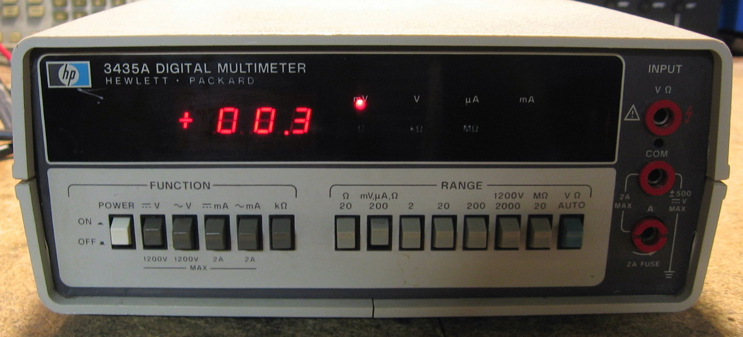
HP 3435A: 3-1/2 digit, five function autoranging multimeter. That pretty much sums it up. Basic DCV accuracy is in the 0.1% class, which is pretty abysmal, but with only 3-1/2 digits, what do you expect. This piece is a prime example of the period in which HP was trying to cut costs and offer low-priced test equipment to compete with other manufacturers, as evidenced by the abundance of plastic parts. (PDF) Grade: B
I picked this piece up for ten bucks hoping to get at least one hour of entertainment. When received, it had the battery pack option, so I removed the dead batteries and jumpered the thing to run solely off of AC. The unit worked fine, but only in auto-range mode. Pressing any of the manual range buttons had no effect - the thing seemed stuck on auto-range. The switches all buzzed out fine, but the three lines going into the HP custom controller IC that select the ranges were either 0 or 2 volts. They are supposed to be 0 or 7 volts as determined by the range switches; each line has a 1K pullup resistor to 7 volts and pushing the switch grounds the line. I could find nothing overtly wrong so in desperation I simply set an external power supply to 7 volts (with no current limiting!) and briefly touched one of the three lines. All of a sudden the 3435A came off of auto-range and the manual selections all worked. But about 5 minutes later, it went back to auto-range by itself. So I touched the remaining two lines with the external 7 volts. Back it went to working properly and has done so now for a couple of days. I have no explanation for this "fix," other than the hybrid IC is full of FET switches and perhaps they got stuck in some weird capacitive state. And I got my desired one hour of entertainment.
I picked this piece up for ten bucks hoping to get at least one hour of entertainment. When received, it had the battery pack option, so I removed the dead batteries and jumpered the thing to run solely off of AC. The unit worked fine, but only in auto-range mode. Pressing any of the manual range buttons had no effect - the thing seemed stuck on auto-range. The switches all buzzed out fine, but the three lines going into the HP custom controller IC that select the ranges were either 0 or 2 volts. They are supposed to be 0 or 7 volts as determined by the range switches; each line has a 1K pullup resistor to 7 volts and pushing the switch grounds the line. I could find nothing overtly wrong so in desperation I simply set an external power supply to 7 volts (with no current limiting!) and briefly touched one of the three lines. All of a sudden the 3435A came off of auto-range and the manual selections all worked. But about 5 minutes later, it went back to auto-range by itself. So I touched the remaining two lines with the external 7 volts. Back it went to working properly and has done so now for a couple of days. I have no explanation for this "fix," other than the hybrid IC is full of FET switches and perhaps they got stuck in some weird capacitive state. And I got my desired one hour of entertainment.
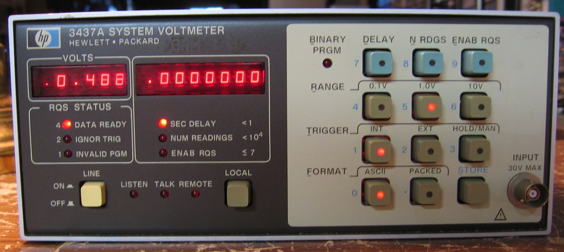
HP 3437A: Very high speed (5000 readings/sec) DC voltmeter. Usually sells for < $20. The front panel switches are not heat staked; they are removable intact. So $20 gets you thirteen $25 replacement switches! Throw the rest of the unit away. Well, maybe not. Several HP calibration procedures use the 3437A, but you can usually get around it if you are clever. (PDF) Grade: B
The display became erratic one day many years later and was fixed by simply reseating the connector on the front panel board.
The display became erratic one day many years later and was fixed by simply reseating the connector on the front panel board.

HP 3455A: 6-1/2 digit autoranging voltmeter, DCV, ACV, ohms. Limited math operations. Autocal reed relays make some nuisance noise. The only thing I don't like about the 3455A is the ohms function which always reads in kilo-ohms. Other than that, it is basically bulletproof. I do want to mention that the 3455As tend to drift pretty badly until they are warmed up (~1 hour). If you don't believe me, short the input, select DCV, 0.1V scale and turn off the auto-zero function. Watch the display move fairly linearly several hundred microvolts. With the auto-zero function enabled, you will see the last digit fluttering about 5-10 uV since it appears the auto-zero only periodically compensates for the drift (like every third or fourth measurement?). But everything eventually calms down. (OM) Grade: A-
I've bought three of these over the years - all broken. One had cold solder joints on the AC RMS board. One had two faulty LM339 comparators on the A/D board and motherboard. One had a bad LM339 on the A/D board, a bad opto-isolator on the motherboard and a bad electrolytic in the P/S. All three needed extensive renovation of the front panel pushbuttons.
Postscript: A few years later, I noticed one of these became very noisy, but only when the guard button was depressed. Turns out that the metal shielding around the terminals is held onto the chassis by a couple of screws. The screws had loosened and a simple re-tightening fixed the problem.
Postscript^2: One day I went looking for something to fix. Sure enough, one of the 3455A units was locked up (no display and unresponsive to button presses). This usually means the uP is waiting for the A/D which never seems to finish. I exchanged the A/D board with one from my other 2 good units and it had no effect. I could force the uP interrupt line low a few times and the thing would start to give me readings on the display, but they were pretty much nonsense and changing functions often locked the machine up again. Bottom line: U4 was causing two FETs to be turned on at the same time (they are supposed to alternate) which dragged the 10V reference down to about 1V and caused the auto-cal functions to fail, thereby locking the machine up. And what was U4 you ask? The dreaded LM399 quad comparator that was the cause of failures in my other two units (at different places of course). So it looks like HP really got a dreadful lot of these components. And who made the LM339's you ask? Well, National Semiconductor of course - the absolute bane of IC manufacturers (see the comments for the HP 3581C).
Postscript^3: Turned on the 3455A I fixed in Postscript^2 above and the thing was giving me flaky readings, especially on ohms. And within a few minutes, the thing went completely unresponsive and totally locked up with no display. In almost all instances, there is a fault with the "inguard" circuitry that does the actual measurements and the nanoprocessor on the "outguard" circuitry just sits and waits idly by. But all of the FET swtiches controlled by the various LM339s checked out OK, as did the A/D converter, so I turned to the outguard circuitry. Indeed, the nanoprocessor on the outguard's daughterboard was not starting up. I jiggled the nanoprocessor board and the 3455A started to work intermittently. To make a long story short, the edge connector's contacts had opened up a bit and were not making good contact. The connector is a dual 15-pin Cinch #252-15-30-201 and HP used this connector for their ubiquitous HP10811 OCXOs in dozens of pieces. Luckily I had a junkbox with an old HP 5328A counter motherboard and sure enough, there was a 252-15-30-201 on it. Out it came, into the 3455A, and all is well.
Postscript^4: The repair described in Postscript^3 was a red herring. Indeed, several weeks later the 3455A hung on startup. When I kept recycling power, it eventually started up. DCV and ACV seemed to work fine, but ohms was completely wacky. In fact, unlike the other modes, the acquisition was not periodic, but rather random as though sometimes the inguard uP was hanging. I spent several weeks off and on trying to chase down a faulty ohms circuit (which turned out to be a wild goose chase). All the inguard P/S voltages checked out OK. Or so I thought. I should have paid attention to my own General Repair Notes (at the bottom of this web page) and checked the P/S with a scope. For when I looked at the 5V line, I saw about 600mV of 120 Hz ripple. And this was at the output of an LM309K regulator! The input to the regulator was dropping down to about 6V at the 120 Hz rate rendering the regulator inoperable for a short time, rendering the uP inoperable also. Anyway, a new input electrolytic capacitor fixed all ills. Tests with the faulty electrolytic were interesting, however. With no load, it tested OK on a majority of my capacitor testers. I've seen this behavior before - namely, once a load is applied, the cap reveals its ailments. I guess the 3455A worked OK on volts because there was slightly less load on the 5V supply than in ohms (the ohms board is indirectly powered by this 5V through a switching DC converter).

HP 3456A: 6-1/2 digit voltmeter, DCV, ACV, ohms. Extensive user options and statistical functions. The successor to the HP 3455A. Completely silent, no fan. This is the default meter I use all of the time (updated: I use the Keithley DM6500 now). Nothing bad to say about it. Well, I do wish it would also do current. (PDF) Grade: A
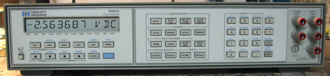
HP 3457A: 7-1/2 digit multimeter, DCV, ACV, DCI, ACI, 2-R, 4-R, Frequency. OK, it says 7-1/2 digits, but it is really 6-1/2 with the seventh digit stored in an internal register that can be read out subsequent to the measurement. I have the HP 3455A and HP 3456A, so naturally I had to have the HP 3457A. They did make an HP 3458A (and still do) but the only way I'm ever going to have one of those is if I win the lottery. The 3457A I did purchase is in mint condition inside and out. The basic specs are slightly worse than the HP 3456A, but the 3457A has a very extensive set of menus and configuration utilities and also does current and (limited) frequency measurements. The downside is the terrible LCD display that you can't see in dim light. And it needs a power-on LED which will happen soon enough. (PDF) Grade: A-
I was moving equipment around one day and noticed a pretty good rattle when I had the 3457A in my hands. Opened it up and found three screws bouncing around. Inspection showed three empty screw holes in the analog board and the remaining board mounting screws loose. How it got this way is a mystery. Anyway, I secured all the screws and since I hadn't used the 3457A in quite some time, powered it up. The DCV, ACV and DCI/ACI seemed OK, but the ohms was all screwed up. The self-test gave me two error codes: 1) current source, gain selection, input divider error, and 2) amps self-test failure. Since DCI worked and the amps self-test uses the current source from the resistance circuitry, it was clear that the current source was the problem. I got REAL lucky on this one because in less than two minutes, random probing of the current source circuitry with a DC voltmeter showed 8V on one side of an inductor and 2V on the other. This inductor passes the generated current on to a relay and then out the front panel jack. I pulled the inductor (L201, 3.6 mH) and it read about 100e6 on an ohmmeter. I found a 3.3 mH inductor on one of my junk boards which is close enough. In it went - self-test passes and all is well.
Special HP 3457A Bonus Rant: I recently found a cal-lab who would calibrate my 3457A for $125, a true bargain. But, as the adage goes, you get what you pay for, and they did a horrendous job. But that gave me plenty of opportunity to play with the thing and do some more in-depth testing of the 3457A. Now, the basic meter has all the functions, can do 7-1/2 digits, is small and lightweight, and has a host of math functions. Those are the positives. I find it painfully slow and I hate the LCD display. But those negatives are more subjective. Let's get to the performance, because nobody can argue with that. First of all, a 6-1/2 digit DMM is often referred to as a 1,000,000-count meter. But the 3457A is a 3,000,000-count meter. Better you say? Well, guess again. This puts the basic range switching "on the threes," namely 30 mV, 300 mV, 3 V, 30 V and 300 V. And so the meter switches from 10 gigaohm input impedance to 10 megaohm input impedance for inputs greater than 3 Vdc. More egregious, this switches in the input attenuator and so the A/D converter noise goes up drastically. And, of course, the further away from 30 V you are, the further away you are from a calibration point, so the accuracy (non-linearity) comes into play. I don't know about you, but many of my measurements are made near 5 Vdc, not to mention everybody's favorite voltage standard of 10 Vdc. I have made linearity measurements using my Fluke 343A DC calibrator or my special 10 V calibration source through the ESI RV622A voltage divider. No way is the linearity of the 3457A as good as, say, the HP 3456A or the Advantest R6871E-DC. So, I'm going to change my previous A- grade to a solid B. There, HP, take that!
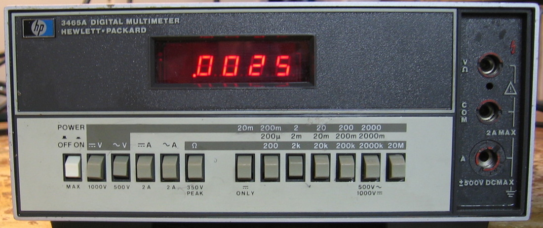
HP 3465A: 4-1/2 digit DMM, DCV, ACV, DCI, ACI, ohms. The predecessor to the HP 3455A and based upon HP's dual slope integrator technique. Has a basic best case accuracy of about 0.02% (DCV). ($CD) Grade: C-
For such an innocuous little piece, this one drove me crazy for a weekend. The previous user had the good sense to at least remove the NiCd batteries, but not after they leaked and pretty much destroyed the P/S board. I rebuilt the board retaining only the necessary parts, not the parts for the battery charger which will never be used by me or anybody else if they have any sense. However, upon power up, the meter was somewhat unstable and gave incorrect readings. After many hours of pulling FETs and op-amps out and checking them, the culprit was simply very dirty pushbutton switches. The designers chose to route all signals through about six switches at all times and several of them were making bad connections, no connections or leaking across adjacent connections. A thorough rinse with tuner cleaner solved the problem and the thing calibrated nicely. It now meets all specs. They tell you when you are young not to believe everything you read. A corollary of that is to always believe what you, yourself wrote. In the general repair notes at the bottom of the page, I wrote to always check mechanical parts first. I should have taken my own advice.
Postscript: There was still something flaky with this unit and I believe it is an intermittent primary on the AC transformer. I have it now wired permanently for an external 9VDC AC adapter.
Postscript^2: The unit started to act up with a flickering display. The problem was traced to a defective pass transistor on the power supply.
Postscript^3: There was still a lingering problem with the switching DC-DC converter inside that was oscillating at about 190 Hz. I traced the problem to corroded solder joints (from the previously leaking NiCd batteries) in an area around the main switching transistor.
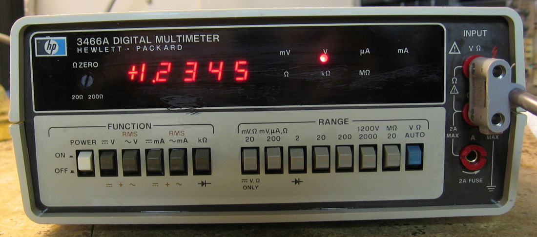
HP 3466A: 4-1/2 digit DMM, DCV, ACV, DCI, ACI, ohms, diode. A slightly better version of the HP 3465A with an average DC accuracy of 0.03%. Somewhat confusing range selection that requires you to look very carefully at the labels to see which buttons are applicable. At least it has an auto-ranging function, but it can take a couple of seconds to arrive at the final range. Seems pretty accurate and doesn't suffer from the two faults I see a lot with cheap DMMs: 1) flipping the leads to get a negative DC voltage gives a different absolute value than the positive voltage, and 2) while it might calibrate nicely at one value, the non-linearity of the measurements is apparent elsewhere. (PDF) Grade: B
Advertised by the seller as doesn't power up. The 3466A has a 6V rechargeable lead-acid battery which supplies, among other things, the voltage to the display LEDs, regardless of whether the thing is running on batteries or AC power. The battery measured -0.3V which would explain the doesn't power up statement. I removed the battery, disconnected the charging board and jumpered the thing to run solely on AC power. After discovering the missing fuse and bypassing the malfunctioning power switch, the 3466A powered up but was completely hosed - stuck on ohms, erratic measurements, etc. There are 14 board-mounted pushbutton switches ranging from 2PDT to 6PDT and each and every pole that I checked was malfunctioning. I guess that this thing sat for 10 years unused and the switch contacts completely tarnished. I drilled a small hole in each switch and flooded it with tuner cleaner. That seems to have cured all the problems and the 3466A functioned nicely and calibrated properly. I haven't decided whether it is worth replacing the battery as this piece will never have enough use to keep it charged.
Advertised by the seller as doesn't power up. The 3466A has a 6V rechargeable lead-acid battery which supplies, among other things, the voltage to the display LEDs, regardless of whether the thing is running on batteries or AC power. The battery measured -0.3V which would explain the doesn't power up statement. I removed the battery, disconnected the charging board and jumpered the thing to run solely on AC power. After discovering the missing fuse and bypassing the malfunctioning power switch, the 3466A powered up but was completely hosed - stuck on ohms, erratic measurements, etc. There are 14 board-mounted pushbutton switches ranging from 2PDT to 6PDT and each and every pole that I checked was malfunctioning. I guess that this thing sat for 10 years unused and the switch contacts completely tarnished. I drilled a small hole in each switch and flooded it with tuner cleaner. That seems to have cured all the problems and the 3466A functioned nicely and calibrated properly. I haven't decided whether it is worth replacing the battery as this piece will never have enough use to keep it charged.

HP 3467A: Four-channel logging DMM. This somewhat unique piece starts out with a basic 4-1/2 digit DMM (circuit design similar to the HP 3466A above) capable of DCV, ACV, ohms, diode and temperature (with an external thermistor). Then it adds a four-channel reed relay based scanner that allows the unit to automatically step through any or all of the four selected inputs. Moreover, the fourth channel can be set as a "reference," and the unit can be configured to display various mathematically related readings on the first three channels (e.g., delta). Normally, all the channels are set to make the same type of measurement. However, it is possible to configure two channels to measure temperature and two channels to measure another DMM function at the same time. Finally, HP added a printer that can also be configured to automatically print at desired time intervals or immediately as the user desires. The chief utility of the 3467A seems to me to be the multi-channel capability. For instance, I once needed to monitor three oven voltages in the Fluke 5440B calibrator plus a certain op-amp voltage. I certainly have four voltmeters and that is what I used. But with the 3467A, I could have done it all. Rather than looking at four separate voltmeters, I could have simply watched the 3467A step through the voltages at about one reading per second. The construction of this piece is kind of strange, having a lot of plastic where HP would normally have used metal at the time. But the real reason I bought this piece is that it gave me an "HP straight flush." That's right - now I have the HP 3465, 3466, 3467, 3468 and 3469. Beat that! (PDF) Grade: B+
Advertised by the seller as working, it basically was after I reseated all the boards. There was a sticking button on the front panel and this was fixed by filing the edges of the hole (thanks HP for making the front panel plastic). The alignment went smoothly and all seemed well, so I turned my attention to the printer. Right before I was going out to buy some thermal printer rolls, the printer mechanism self destructed and ground one of the plastic gears that moves the print head into dust. End of printer. At least I don't have to buy thermal paper. I suppose it is possible to machine another gear. All I would need is a multi-thousand dollar computer controlled lathe. Not that I really have much use for the print capability, but after all, the 3467A is supposed to be a logging DMM. Mine isn't.
Postscript: Hold on there! You know I couldn't live with a malfunctioning printer. The "correct" replacement gear was identified by a fellow on eevBlog and suitably procured. I put the word "correct" in quotes, because although the replacement gear had the correct number of teeth (30) and the right diameter, the shaft hole was 2 mm instead of 2.5 mm and the height was a lot larger than the required 4.5 mm. A pal at work had the right machinery to mill the gear to the proper dimensions, and all was good. Well, not quite, as the printer only printed a portion of each character. I disassembled the printer and stared at the guts for about 30 minutes before I realized that the print head was not properly placed. Loosened a few screws, moved the head until I felt it click into place, and tightened the screws. Perfecto.
Postscript^2: One day the print button didn't work. Nor for that matter did half of the front panel buttons. This was easily traced to the MM74C922N keyboard encoder chip which was suitably replaced. And who made the broken IC? Well, National Semiconductor of course! Need I say more?
Postscript^3: Preemptively replaced the two Rifa 0.001uF suppression capacitors from Line-Gnd and Neutral--Gnd. Funny, those are supposed to be Y-class caps, but they were marked X-class. The Panasonic replacements were class X/Y.
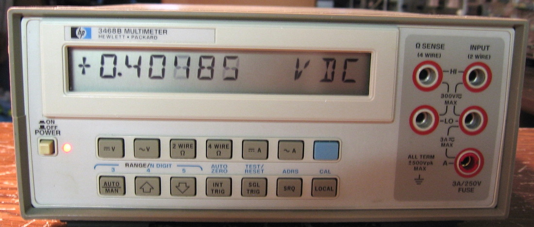
HP 3468B: Modern 5-1/2 digit multimeter. All the usual functions plus amps. LED power lamp added. For those who couldn't afford the 3456A, HP came out with a low price series of DMMs. Very easy calibration all done in stored look-up tables. My only complaint is the LCD display that you can't read in dim light conditions. If you can snag one on eBay for less than $75, go for it! (OM) Grade: B
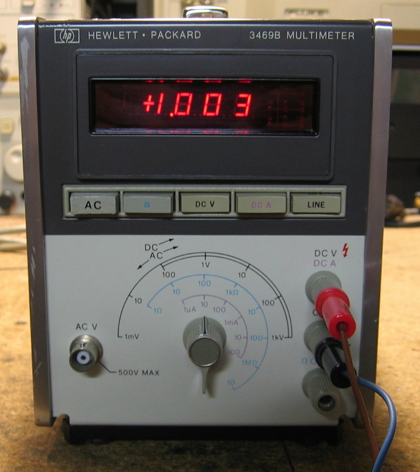
HP 3469A: Your basic 3-1/2 digit multimeter doing DCV, ACV, DCI and ohms. Basic accuracy is about 0.2%, but with only three significant digits, who really cares what the accuracy is. Has an odd combination of range switching and input jacks. Most of the discrete circuitry is for the attenuation, impedance converter, AC amplifier and ohms current source. The actual measurement is done by a custom two-chip digital panel meter using the usual dual slope technique. The ohms function has a nice feature - on the lowest range it uses an AC current source to reduce any thermal offsets in low resistance connections. ($CD) Grade: B+
This piece eventually worked correctly once I cleaned the range switch and let the cobwebs inside the capacitors burn up. The biggest problem was a missing AC button on the front panel. But a pal at work was kind enough to make one on his 3-D printer. A little gray paint and some dry transfer lettering and presto!
This piece eventually worked correctly once I cleaned the range switch and let the cobwebs inside the capacitors burn up. The biggest problem was a missing AC button on the front panel. But a pal at work was kind enough to make one on his 3-D printer. A little gray paint and some dry transfer lettering and presto!
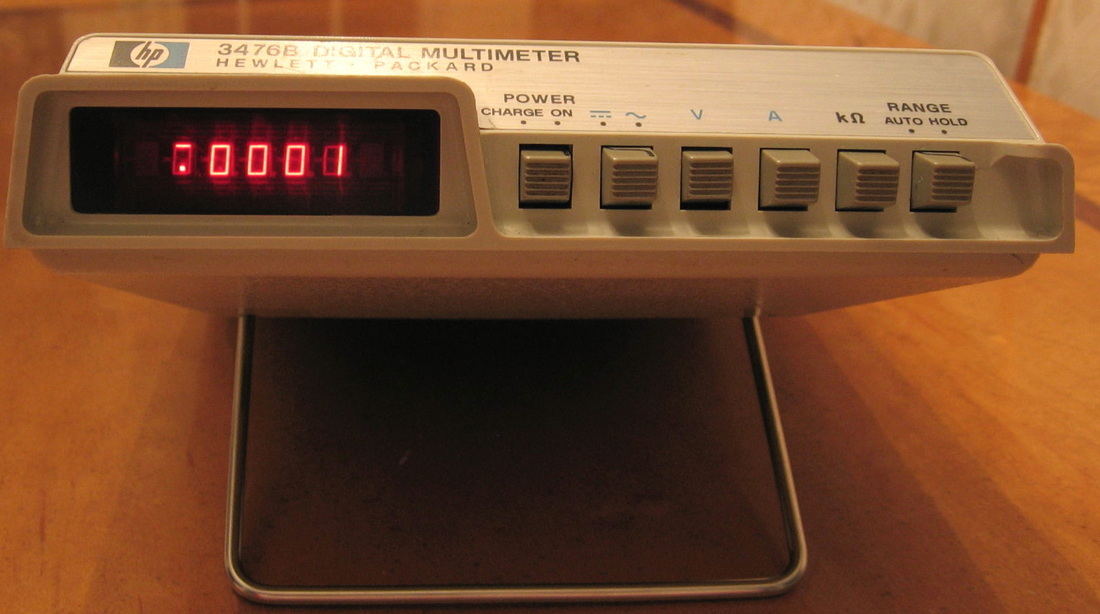
HP 3476B: HP's least expensive ($275 in 1980) DMM. This is a 3-1/2 digit DMM using 5 LEDs (like those found in their calculators of that era). Why 5 LEDs for 3-1/2 digits you ask? Because they waste an entire digit for the decimal point. The specs are not particularly good and I would put this somewhere between a $20 Radio Shack DMM and a $100 Wavetek DMM. But you have to admit, it is really cute! (PDF) Grade: B
The "B" model operates on AC or battery. But that's only if there is a battery inside - which there wasn't when I received it. At least I didn't have to worry about leaking batteries. The "power supply" is basically a current source to charge the batteries - the thing then basically runs off of the batteries. The 3476B requires 4 sub-C NiCd batteries which were readily available.
The "B" model operates on AC or battery. But that's only if there is a battery inside - which there wasn't when I received it. At least I didn't have to worry about leaking batteries. The "power supply" is basically a current source to charge the batteries - the thing then basically runs off of the batteries. The 3476B requires 4 sub-C NiCd batteries which were readily available.

HP 3488A: Switch control unit. Contains option boards with various relays. Five slots are populated. LED power lamp added. This was cheap and like many of the things I have, pretty useless. My initial thought was to use it to route signals all over the lab. However, the frequency response is horrific. No sense routing a 10 MHz signal if I'm going to lose 5 dB. But I have enough plug-ins in this unit to route probably 50 signals around. (PDF) Grade: B
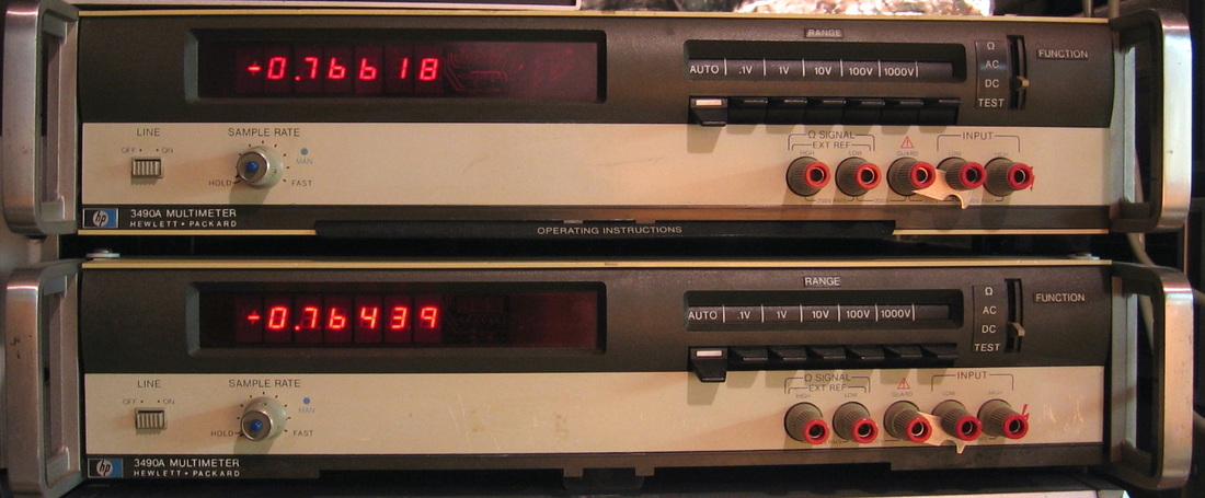
HP 3490A: AC, DC, ohms digital 5-1/2 digit meter. Digitally controlled through a ROM based state machine. Resistance measurements must use the 4-wire configuration - a pain. Cute self-test functions. This was the predecessor to the microprocessor controlled 3455A. Or should I say "nanoprocessor" controlled since the 3455A processor was a special limited instruction set gizmo designed by HP. The 3490A does an admirable job, however, and the circuitry is very understandable. (PDF) Grade: B
Two of these, one worked, one didn't. The faulty one needed a new 30V regulator and the wire from the AC to the FET board reseated.
Postscript: Whenever I'm bored and looking for something to fix, I start with a piece that I haven't turned on in a few years. And the 3490A didn't disappoint. Although both units worked flawlessly (for a few minutes), one made a big pop and smoke poured out the back. The usual Rifa suppression cap across the AC plug let out the magic smoke. The other 3490A's cap was still intact, but had a large crack down the middle revealing the metal inside - so that one wasn't long for this world either. Both were replaced (with non-Rifa 0.22uF X2 versions) and all is well.
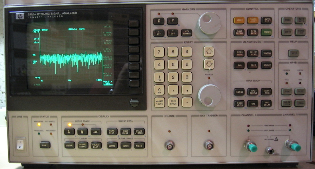
HP 3562A: Low frequency two channel spectrum analyzer to 100 kHz. 800 point FFTs performed. Average noise level about -135 dBm//Hz. A selection of measurements and menus that would keep anyone occupied for hours. If you want to do audio analysis, this is the piece. Distortion, channel correlation, time, frequency, you name it - the 3562A does it. I only wish it went higher than 100 kHz. The CRT brightness control needs to be turned up to about 75%. I hope this doesn't mean the tube is on its way out. (PDF) Grade: A
Postscript: Having later acquired the HP 8980A Vector Analyzer, I realized that the HP 3562A also has the HP 1345A display. Now being familiar with those adjustments, I was able to properly align the display on the 3562A and achieve normal CRT brightness.
Postscript^2: One day, I turned on this piece and about two minutes later, the CRT flashes and then goes dark. Having fixed a few of these HP 1345A displays, my guess was yet another 2.2 uF tantalum. A quick check of the 15V rail on the 1345's stroke board showed a short to ground. But this time, I kept my eye on a 6-1/2 digit ohmmeter while I was checking the tantalums and settled on the one with the smallest resistance. Popped that out, put in a 1 uF electrolytic, and everything is back to normal. Took me about 5 minutes.
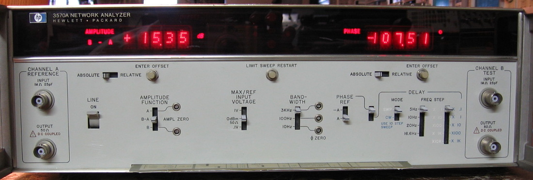
HP 3570A: Narrowband network analyzer. The brother of the HP 3575A. Works with an HP 3330 or equivalent signal generator as it needs Sig, Sig+20MHz and 1MHz inputs. Have two, one with a bypassed filter (3rd pole). Essentially the 3570A with the 3330B is what people used before spectrum analyzers. You get an amplitude and phase reading at each frequency. You can also sweep the signal input and the 3570A will display the group delay. Of course, you could manually take two phase readings at different frequencies, and calculate the group delay yourself. The piece has two channels, but it really is a misnomer since channel A is always hooked up as a reference channel. (PDF) Grade: B+
The first of two had a blown P/S due to a faulty Zener which tripped the SCR. Replaced both the Zener and the SCR. But that was only problem number one. The real problem was a blown IF third-stage crystal on the B channel. With no chance of getting a 100 kHz crystal like what HP used, I bypassed the third stage on both the A and B channels (in order to preserve phase - it's a network analyzer after all). The second unit worked fine electrically but had a faulty slide switch. These are not the usual slide switch, but rather the type that HP uses that slides across the circuit board. I salvaged the tiny gold fingers off of a similar slide switch of an old HP 8013B, heat staked it in rather cleverly, and that was the answer.
The first of two had a blown P/S due to a faulty Zener which tripped the SCR. Replaced both the Zener and the SCR. But that was only problem number one. The real problem was a blown IF third-stage crystal on the B channel. With no chance of getting a 100 kHz crystal like what HP used, I bypassed the third stage on both the A and B channels (in order to preserve phase - it's a network analyzer after all). The second unit worked fine electrically but had a faulty slide switch. These are not the usual slide switch, but rather the type that HP uses that slides across the circuit board. I salvaged the tiny gold fingers off of a similar slide switch of an old HP 8013B, heat staked it in rather cleverly, and that was the answer.
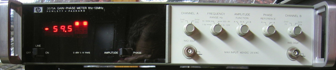
HP 3575A: Gain and phase meter. Measures the amplitude ratio and phase between two inputs. Rated to 13 MHz but performs well to >20 MHz. Phase accuracy < 1 deg in a typical case. The 3575A essentially duplicates the function of the 3570A. However, it was designed as a broadband instrument rather than the narrowband 3570A. Mine does not have the second display option which allows one to see both the amplitude and phase measurements at the same time. I have to toggle a switch. (PDF) Grade: B+
Just your typical "reseat the boards." Love it! I also had to replace the two front panel rocker switches whose levers had cracked off. I couldn't get the right size switch so I had to enlarge the front panel holes a bit.
Postscript: After a few years of sitting on the shelf, I turned this on and a few seconds later the unit became unresponsive to inputs, showing overload on both disconnected inputs. A quick check of the power supplies showed most of them completely wrong. I removed the P/S board and found a short on the -12V rail to ground on the remaining motherboard. Pulling all the other boards out one at a time revealed the short was on the A6 board - one of those yellow cylindrical tantalums that HP is fond of. Replacing the cap restored everything to normality.
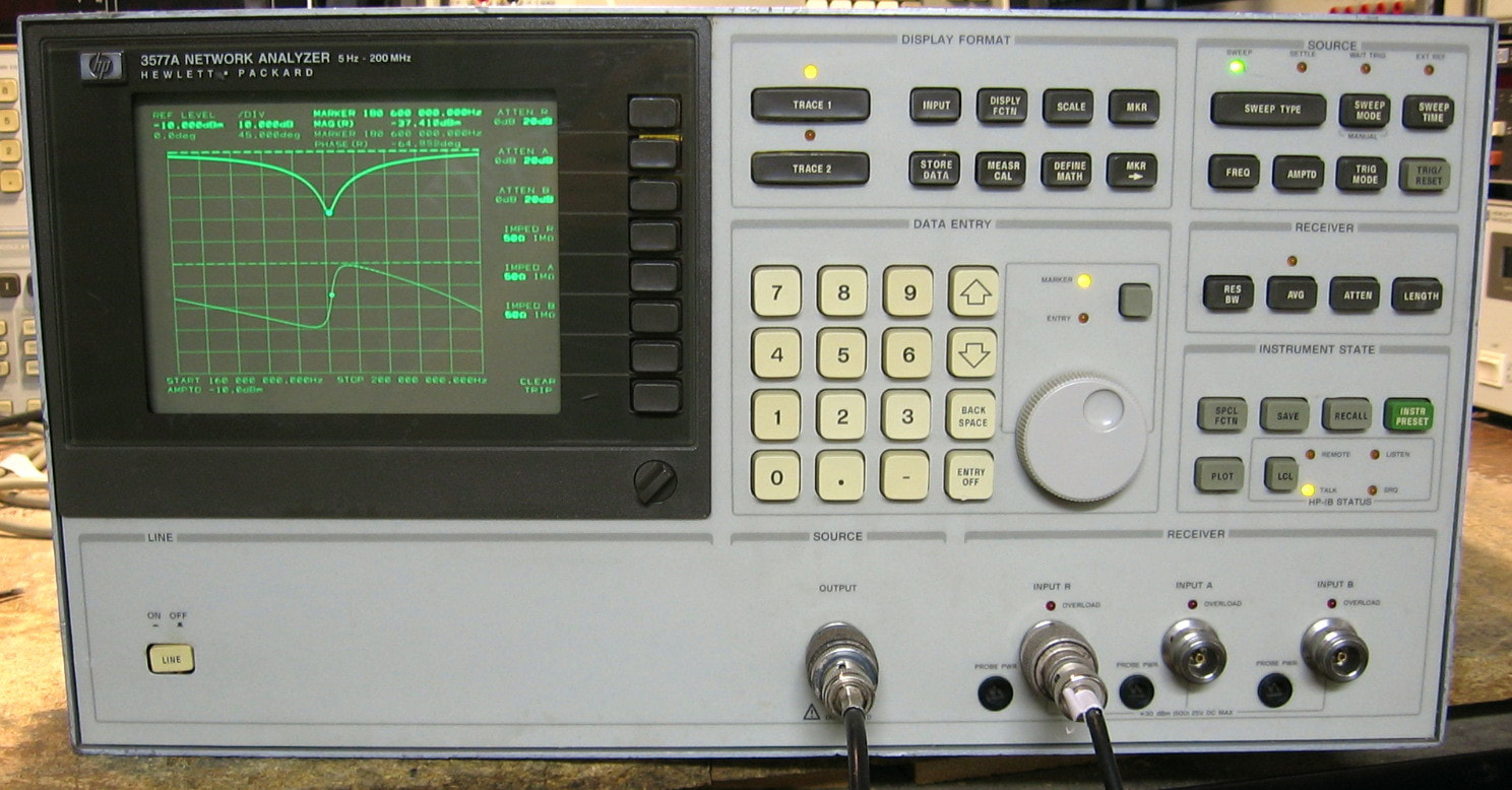
HP 3577A: Network analyzer, 0 - 200 MHz. OK, it is a bit restrictive in upper frequency limit for today's stuff, but then again, all of my stuff is from the same time frame as this piece. I won't go into any of the functions and specs - either you know all about network analyzers or it would be too mysterious for you if you don't (incidentally, the photo shows the magnitude and phase for a stub tuned notch filter made from an open piece of coax). The bare 3577A has one source and three receivers, but was also made to connect to the HP 35677A s-parameter test set for true s-parameter measurements. Sold in 1990 for $26,000, the 3577A is a marvel of well thought out design and construction; I especially like how the boards have silkscreened white rectangles around areas of parts with labels describing the function. Let's just say I wish all my pieces were like this. Well, almost - the thing does weigh 67 pounds! (PDF) Grade: A
Advertised by the seller as having a display that "flashes in and out" and "overloads at low frequencies," I figured I would take a chance at $69 (plus shipping). When received, the display was randomly flashing bright and dim with a lot of extra lines. The display in the 3577A is the venerable HP 1345A used in many HP pieces (like my HP 3562A, HP 8980A and HP 8981A). I pulled the 1345A out of the unit and all the low voltages checked OK. I then tried to adjust a few pot on the HV board and must have inadvertently shorted something with my screwdriver, since I heard a lout pop, the 3577A shut itself off, and the display never lit up again. Since I have essentially two HP 8980As (the 8980A and 8981A), I pulled the 1345A out of the 8980A to replace the one in the 3577 I just fried. This was easier said than done and took about four hours. Indeed, the mounting points were different as were several of the boards. I ended up using the 1) stroke, 2) control, 3) memory boards from the original 1345A in the 3577A and the 1) LV P/S and 2) HV P/S from the 1345A in the 8980A. Anyway, the surgery was successful and my 3577A now has a properly operating supply. As far as the "overload at low frequencies," the 3577A will indeed flash an occasional overload if you set the source amplitude to about -10 dBm and then run the thing below 100 Hz. This probably is akin to LO feedthrough in a spectrum analyzer. So it is pretty easy to avoid this condition. Whether it can be mitigated with an instrument calibration, I'll never know. The 3577A passes all the confidence self-tests and I'm going to leave it like that. And I really should now get back to that broken 1345A that's sitting on my bench....
Postscript: I traced the fault with the HP 1345A to a faulty CA3094A on the HV board that serves as the oscillator in the primary side of the switching power supply for the CRT. I mistakenly ordered a CA3904 instead of a CA3904A; the former is OK for a 24V supply and the latter good for 36V (the HP 1345A provides 30V). The 24V-rated part came in the mail first and so I took a chance while I am waiting for the 36V part. Seems to work fine, but I spent about 5 hours in needless debug since when I powered up the 1345A, the test pattern appeared for a few seconds and then the screen dissolved into a fuzzy blob. Turns out that I had one of the CRT's control grids hooked up to the wrong pin on the board. Instead of going to a 105V supply (through a pot), it was going to nothing (this was the provision for an external pot) except a small capacitor to ground. The grid accumulated charge from surrounding grids and charged up the cap. This is why the image appeared for a few seconds until the cap fully charged. As soon as I corrected my mistake, the 1345A performed flawlessly and is back in the HP 8980A since the one I had pulled was used for the HP 3577A.

HP 3581C: Selective voltmeter a.k.a. wave analyzer. Audio range to 50 kHz. Dynamic range > 80 dB. Can be used tediously but accurately to measure THD, for instance. This little throw-away piece is actually very capable and I like it a lot. The tuning mechanism is a true HP mechanical masterpiece. (OM) Grade: A-
Replaced faulty A3U4 and A7U8 that were causing the AFC and the sweep functions to malfunction. Also replaced the power light bulb.
Postscript: After sitting dormant for a few years, I fired this puppy up only to find that the AFC was not working. Consulting the block diagram led me back to the A7 board and the problem was isolated to only a few ICs. But one of them had the "double squiggle" markings of National Semiconductor, so that was the one I surmised was the problem. And so it was (a CD4019). I've learned the lesson the hard way - National Semi ICs of the late 1970s suck big time. They should always be your first suspect in any faulty logic. In fact, the only parts that are guaranteed to be even more problematic are Sprague (electrolytic) capacitors. Funny, National Semiconductor was essentially started by Peter Sprague. I rest my case.
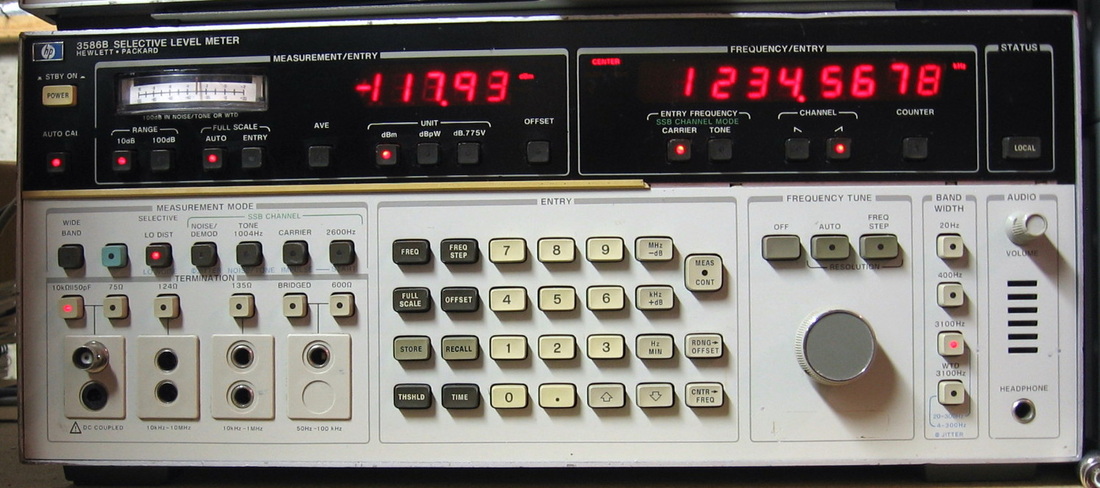
HP 3586B: Selective level meter, 200 Hz to 32.5 MHz. Nothing more than a very good superhet receiver with an extremely accurate S-meter. The auto AGC is very annoying. Now used by many hams for VLF work. The best thing about test equipment designed for the telco industry is that nobody needs these things now. Hence they are dirt cheap. OK, the really best thing about this piece is that the sensitivity is maintained all the way down. So they make superb AM radios. That's if you like 3.1 kHz audio. And if you like having to tune 1850 Hz off due to the built-in offset. (PDF) Grade: A-
Boy was this a pain in the butt. The NiCd batteries had leaked and caused the regulator board to catch fire. Burnt a hole clean through the board. I removed all (about 80) parts from the board, rebuilt the board jumpering over the now non-existent traces, and replaced all of the parts. That only fixed the regulator board. One of the three pass transistors in the main P/S had also blown, so I replaced all three. Similarly for the 6.2V Zener in the main P/S. Then the 400 Hz filter didn't align correctly, so I replaced C106 through C109 on that board. I also added a 12V regulator and a CTS 10 MHz OCXO.
Postscript: One day, the 3586B started up and threw error E3.1. Normally, I wouldn't care, except that it prevented me from seeing the amplitude display. But the unit seemed to be OK otherwise. The service manual says that E3.1 means that the 2nd LO is unlocked and indeed when I took the cover off, there was a lit red LED on the A11 board meaning "unlocked." The 2nd LO is a phase locked oscillator using an inductor, crystal and a varactor for tuning. Evidently over the years, one or more of them has drifted in such a way that the varactor needed to show about 10 volts on a certain test point to achieve lock. But there is a comparator on this voltage line that throws the unlock condition if the voltage is greater than 8 volts. There is a 2.4 pF capacitor in parallel with the varactor and I removed it. This dropped the tuning voltage at the test point to -0.5 V (it is nominally supposed to be -1.5 V), the E3.1 went away, and all seems OK now. I could probably achieve the desired -1.5 V by tuning the inductor; however, the tuning slug has cracked and I'm afraid I will really screw it up if I try to move it.
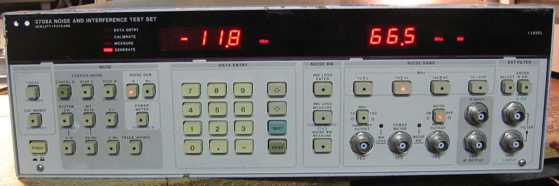
HP 3708A: Noise and Interference Test Set. This is a rather specialized piece, used predominantly for bit error rate testing, that adds controlled levels of noise and interference to a signal. Built for insertion typically between a down-converter and a digital radio, it only offers capability for 70 and 140 MHz carriers. Basically, the 3708A has three functions: 1) power meter, 2) noise generator and 3) C/N or C/I summation. The power meter measures signals in the range 10-180 MHz, +6 to -55 dBm, with a typical error of 0.1 dB. The noise generator produces band-limited Gaussian noise from about 6 to -80 dBm with four choices of internal bandwidth filtering. The C/N or C/I summation function is really what this piece was designed for, however. Input a signal into the IF-in connector (or use the built-in 0 dBm reference signal at 70/140 MHz), dial in what carrier-to-noise ratio you would like, and voila, the IF-output jack produces the signal plus noise. Moreover, if the IF-in power changes, the 3708A senses the new input power in a few msec and adjusts the additive noise to maintain the same C/N. The same basic principle is used by the 3708A if one takes a second signal generator and inputs an interferer into the I-input jack. There are numerous other input/output jacks and assorted functions that you can guess by looking at the front panel. Suffice it to say that the 3708A can also measure cable loss, filter bandwidths, and can accommodate external filters. Unfortunately, my unit is the standard 75 ohm version - I would have liked the 50 ohm option. Having said all of this, the 3708A essentially contains a noise generator, a power meter, an attenuator, a simple oscillator and a signal adder. All the functions mentioned above can be performed with these five elements. So why did HP charge about $25,000 for this piece in the mid-1990s? Well, the answer actually is quite simple. Sure, one can build those five elements for not much money. But try to get anywhere near the accuracy that the 3708A advertises. This thing is a good order of magnitude more accurate than a normal power meter, normal attenuator, normal signal generator, etc. And for good reason; indeed, just 0.5 dB of C/N error can often induce a times-ten change in bit error rate. So in order to test digital radios, you really do need exquisite accuracy and stability that maintains that accuracy over temperature. One peek inside and you will be convinced (if not, read the July 1987 HP Journal article). Gee, now I have something to use with my HP 3764A Transmission Analyzer! (PDF & OM) Grade: A-
Advertised by the seller as "coming from a working environment." I gave that as much weight as a used car salesman saying "only used by Grandma to drive to church on Sundays." But I was willing to risk $100, because, quite frankly, I'm running out of cheap things to buy. The seller's picture showed one front panel button missing, and closer inspection upon receipt revealed that the switch was pretty much toast and the LED inside the switch was faulty. I used one of my spare HP switches (see the description for the HP 3437A) without incident. But when I went to remove the LED, I found that one of the leads was sticking through the hole with no trace of solder. I mean, it wasn't like the solder cracked. There simply was a pristine gold through-hole with no trace of solder. I'm really surprised that this got by the HP Quality Control Inspector. The red front panel plastic window was glued down by the previous owner with some homemade clips because the trim piece between the window and the top of the main panel was missing. A new trim piece was therefore manufactured on a 3-D printer. The piece seems to work fine, and passes all the self-tests except for one: checksum error on EEPROM. That doesn't bode well, since the EEPROM contains cal constants that were loaded for this particular instrument when it was initially calibrated by HP. But I will have to wait until the service manual arrives and see what my options are. Maybe it will be like the Marconi 2018 which has a hidden function to recompute and store the checksum
Postscript: Well, the service manual arrived and thank God the change sheets were included. The EEPROM contains 32 calibration constants (specific to the unit and originally programmed by HP at build time) which can be read and written over the GPIB bus. But before getting to that, I noticed that Self Test #6, which prints out on the 3708A display the value of the checksum, changed every time I ran the test. That led me to suspect that the EEPROM was itself bad. Upon further inspection, I also noticed that the EEPROM was an Intel 2817-A. That was a later rev part - the correct part is supposed to be the 2817 which uses 21 volts for programming (the A model uses Vcc = 5 V) So I ordered the correct part. While I was waiting, I borrowed a LAN-GPIB converter from work and hooked it up to the 3708A. The first thing I did was to read out all of the constants. Suspecting that some would change each time I read them, because the checksum on the display changed, I was somewhat disappointed as repeated reads from the EEPROM yielded the same values. Curious how the 2817-A had the correct serial number for the 3708A (two of the stored constants), so someone had managed to put the wrong EEPROM in and reprogram it at some point. Anyway, I decided to see if I could program the displayed checksum back into address 0 (this is the essence of Self Test #6: to compare the calculated checksum with the stored checksum). But before I did that, I lifted pin #1 since I didn't think it was a good idea to have 21 volts (with little or no external current limiting) on the read/busy output line of the chip which would be pulled low (yes, they changed the pinout of the -A version). No matter what I did, every time I programmed the chip, the display would change to a wrong value and a subsequent read of the EEPROM would produce a wrong value. Fast-forward a few days and the correct EEPROM arrived. At least that one produced the same checksum every time I ran the self-test. So I proceeded to try and write the 32 values I had previously gotten from the old chip. Again, the thing would not take my numbers. For instance, I sent over the GPIB bus the command "SOFT, DWR, 11, ENT, 12.34, ENT" which should write 12.34 as the 11th cal constant. The display would briefly flash 12.34 and then I would get a number like 76.44. Subsequent application of exactly the same command would lead to the same result, except the display would say 76.43. Then 76.42, ... What's going on? I hooked up a scope to the write enable and chip enable lines of the EEPROM and saw that sometimes the write enable would go low, but the chip enable wouldn't. All very confusing, because when that happened, the display would stay at the correct 12.34 value. But sending the command, "SOFT, DRD, 11, ENT, TRIG" which reads out the 11th constant would give me the 76.42 kind of number. Finally, in desperation, I decided to send both commands at once, namely "SOFT, DWR, 11, ENT, 12.34, ENT, DRD, 11, ENT, TRIG", i.e., a write immediately followed by a read. As if by magic, the display flashed a few times but stayed at the correct 12.34 value and a subsequent read verified that the EEPROM finally had stored that value. It's as if the uP needs to be told to write the EEPROM and then read it to verify it before it actually claims victory. From there, it was just tedious to enter all of the 32 constants, run the self test to get the calculated checksum, and then use the same procedure to write the checksum into constant #0. Three successive passes of Self Test #6 convinced me and put this one to bed. I suspect the LAN-GPIB converter I was using (Tek AD007) was not properly interfacing with the 3708A because the computer display never showed any return value off the GPIB bus to any command I sent that is supposed to return a measurement. This may have been the root cause of the problems I had writing the EEPROM. I'm not inclined, however, to pursue it any further.

HP 3709B: Constellation analyzer, 1 - 80 MHz. This is a somewhat odd and redundant piece that is essentially a two-channel sampling scope with some automatic measurement capabilities. It is redundant because my HP 8980A and 8981A can both do the same thing. The unit must be supplied I- and Q- inputs and a clock signal. It will then either display the eye pattern for the I- or Q- channels, or the constellation. That's about it. There are no time base controls - the thing autoranges to always put two clock cycles on the screen. Shown in the picture is a vague attempt with two signal generators to get something resembling the constellation for QPSK. Because there is no noise on the inputs, most of the 3709B's measurements are zero. The background grid for the desired constellation is selectable via a switch. But they mounted the switch on the rear panel for some unknown reason. Once again, I simply can't let a late model (1990) HP piece, which sold for $14,000, be thrown away, so I coughed up $25 for this one. (OM) Grade: B+
Advertised by the seller as non-functional. The picture showed the CRT dark and all the front panel LEDs lit. The LEDs all being lit indicated to me that the processor was hung in the initial boot and/or self-test. Not a good sign. But the fact that the CRT was dark indicated some sort of P/S failure and my hope was a bad P/S was the cause of the processor hanging. Upon receipt and power up, only three of the four internal P/S LEDs were lit; the -15V LED was off. Remembering my experiences fixing my HP 8981A (which has the same basic HP 1345A display), I unplugged the power lines to the CRT unit only to find that the -15V LED now lit up. After restarting the device, I was pretty sure it was functioning (although I couldn't see anything on a dark CRT) because all the internal processor board LEDs lit and the relays were clacking away. A quick ohmmeter check showed that both the 15V and -15V rails of the main CRT board in the HP 1345A were shorted to ground (exactly the same failure as in my HP 8981A). It was relatively easy to find the two shorted 2.2 uF tantalums. Something was still bothering me, because the HP 1345A display module takes 15, -15 and 5V. So if the 15V was also shorted (like the -15V that brought down the entire 3709B's -15V supply), why was the 15V P/S LED still lit and why was 15V found on several test points on the main analog board? I discovered that the HP 1345A in the 3709B is not quite the same as the one in the 8981A. It has a small extra board tacked on and an external pass transistor. The board is supplied 24V from the 3709B and the pass transistor supplies the 15V to the HP 1345A. The small board contains an SCR and an SCR controller. In any event, the CRT module was not getting 15V and I traced back to the P/S to find out that 24V wasn't being supplied. I dissected the P/S only to find an internal 3A fuse in the 24V path that had blown. Replacing the fuse brought the unit back to life. Why HP simply didn't feed 15V to the HP 1345A directly is beyond me. It could have been that the earlier 3709A model used the HP 1340A display, not the 1345A, and the existing 3709B P/S had insufficient 15V power to run the 1345A. See postscript below.
Postscript: Found the service manual on eBay for twenty bucks, so I snagged it. I'm sure it will come in handy one of these days. In the meantime, I ran through the performance checks and it is dead-on in every test. The service manual was for a slightly earlier version and only references the HP 1340A display, which as mentioned above is supplied an unregulated 24V. The 3709B 15V supply is from a 7815/TO-3 regulator which is only good for about 1A. Since the 1345A display draws >1A, that is why they couldn't power it directly and had to revert back to the 24V supply with the supplementary pass transistor.
Postscript^2: Another day, another shorted 2.2 uF tantalum. This one was on the 15V line of the HP 1345A display. That's about the fifth one of these yellow cylindrical 2.2 uF tantalums that I've pulled out of various HP 1345A displays. I'm beginning to see a pattern here....
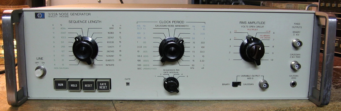
HP 3722A: Pseudorandom noise generator. Back in the late 1960s when this piece was conceived, a noise generator based upon a feedback shift register was still a novel concept. Today it is the norm and this entire unit could be replaced by a single IC. However, HP did manage to use about 400 discrete transistors to produce a circuit containing a 20 bit shift register and the unit will produce both a digital output and a true analog waveform. The left knob sets the number of shift register bits to use (4 to 20) and thus the length of the pseudorandom sequence. The middle knob sets the underlying clock rate. The "infinite" setting for the sequence length seeds the shift register with values obtained from a noise diode so the unit will generate true Gaussian noise. In this case, the middle knob controls the bandwidth of the Gaussian noise. Amplitude control is performed with the right knob. (PDF) Grade: B+
Nothing much to do here except replace the main filter capacitor in the 22V supply that was causing 120 Hz spikes to appear in the analog output.
Nothing much to do here except replace the main filter capacitor in the 22V supply that was causing 120 Hz spikes to appear in the analog output.
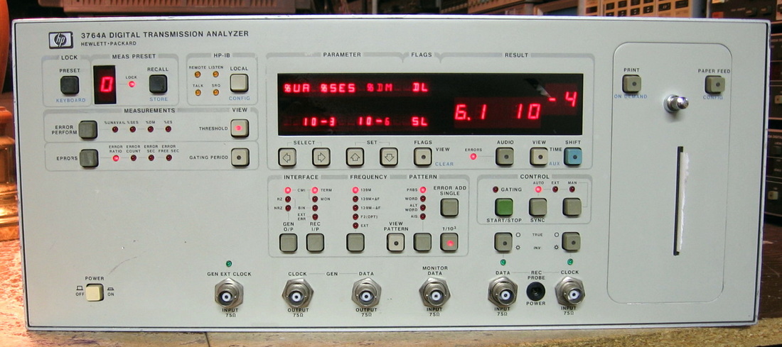
HP 3764A: Digital transmission analyzer nominally for E3 testing at 139.264 MHz. See the description below for the HP 3764A (Option 002). This unit has no options installed. (OM) Grade: B+
This piece was advertised as "powered up, then shut down, no further testing could be done." That's kind of an ambiguous statement. When turned on cold, did it always power up for a few minutes, or did it eventually just permanently stop functioning altogether? Well, I guess I will just have to fork over the $5.99 and find out! On receipt, the fan came on, the power supply diagnostic LEDs all lit properly, the uP activity LED blinked like it should, but the front panel was completely dark and unresponsive. This piece was a classic example of fix-by-inspection. On the middle of three boards mounted to the front panel is a toroidal inductor. This inductor passes the 5V to the display/keyboard controller board. Only problem was that one of the leads of the inductor was pulled out of the board and the inductor was waving in the breeze. Remounted the inductor, unit works fine. Total diagnostic and repair time: 30 minutes. Update: OK, I guess I need more than 30 minutes - I recently found a problem with the front panel Receive Monitor Jack. This was traced to a faulty relay, A11K6. Fixed that too. While I was inside, I modified the unit to take 2xAA alkaline batteries for backup.
Postscript: Preemptively replaced the two Rifa 0.01 uF Y-caps used after the bridge rectifier with non-Rifa 0.01 uF Y-caps. I'm not sure why HP used suppression caps - they really only needed 0.01 uF caps with a 250 VDC rating. Perhaps that's what they had in stock.
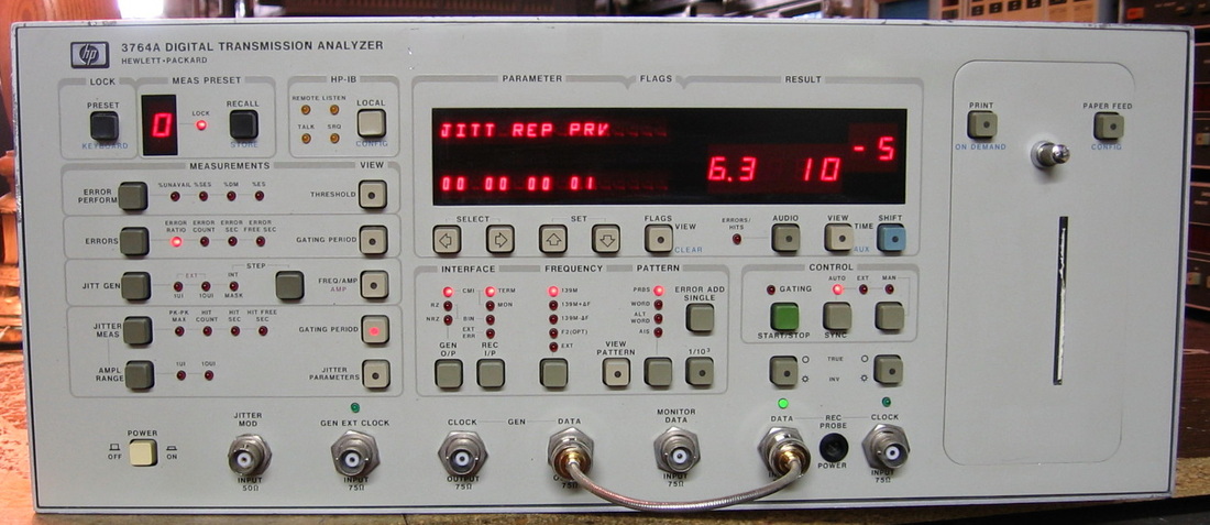
HP 3764A (Option 002): Digital transmission analyzer nominally for E3 testing at 139.264 MHz. Measures and calculates various bit error statistics, generates and measures jittered clocks and has an internal printer to log results. Another telco abandoned machine at rock bottom prices ($9.95). I don't have an E3 modem to test, so this piece is pretty useless. But it was so much fun to work on that I bought another ($5.99). Well, it isn't completely useless, because my newly acquired HP 3708A Noise and Interference Test Set allows me to actually play around with the effects of SNR on Bit Error Rate (not that I couldn't just look it all up in a textbook!). (OM) Grade: B+
The -5V P/S read -0.7V upon receipt. One of the main diodes in the switching P/S had blown open. I replaced the pair responsible for -5V. The jitter functions were also misbehaving. This was traced to a faulty Harris 5195 op-amp which was suitably replaced. That still didn't fix everything. Some cold solder joints on the jitter receive board received a touch up and now everything is in spec. Also modified the battery backup charging circuitry and added 2xAA alkaline batteries
Postscript: One day, I turned the piece on and there was no power to the front panel and the (DC) fan was sputtering. Turns out that one of the main diodes in the switching P/S responsible for 5V had blown open. Moreover, a protection diode between -5V and ground had blown shorted, taking out the -5V supply too. The faulty parts were replaced and all is well again.
Postscript^2: Preemptively replaced the two Rifa 0.01 uF Y-caps used after the bridge rectifier with non-Rifa 0.01 uF Y-caps. I'm not sure why HP used suppression caps - they really only needed 0.01 uF caps with a 250 VDC rating. Perhaps that's what they had in stock.
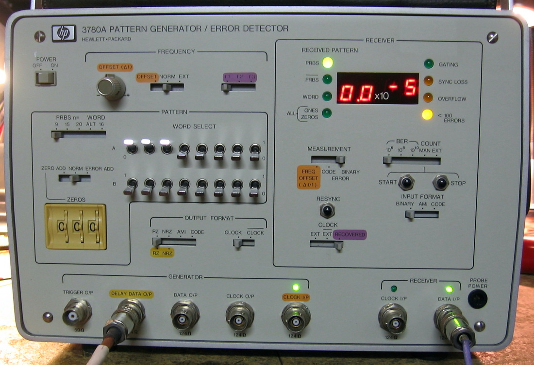
HP 3780A: Pattern generator and error detector. Similar to the HP 3764A above, this piece generates various signals that would go through a device under test and back into the unit to have the error rate calculated. Somewhat confusing front panel unless you speak the lingo (at least it is color coded!). Totally useless from a general laboratory sense. Even more totally useless to me because all the front panel connectors are triax. The only reason I bought this was because I had a beautiful hard copy service manual sent to me by mistake and it needed some use! (OM) Grade: B
Was intermittent, but simply needed to have the boards reseated.
Was intermittent, but simply needed to have the boards reseated.
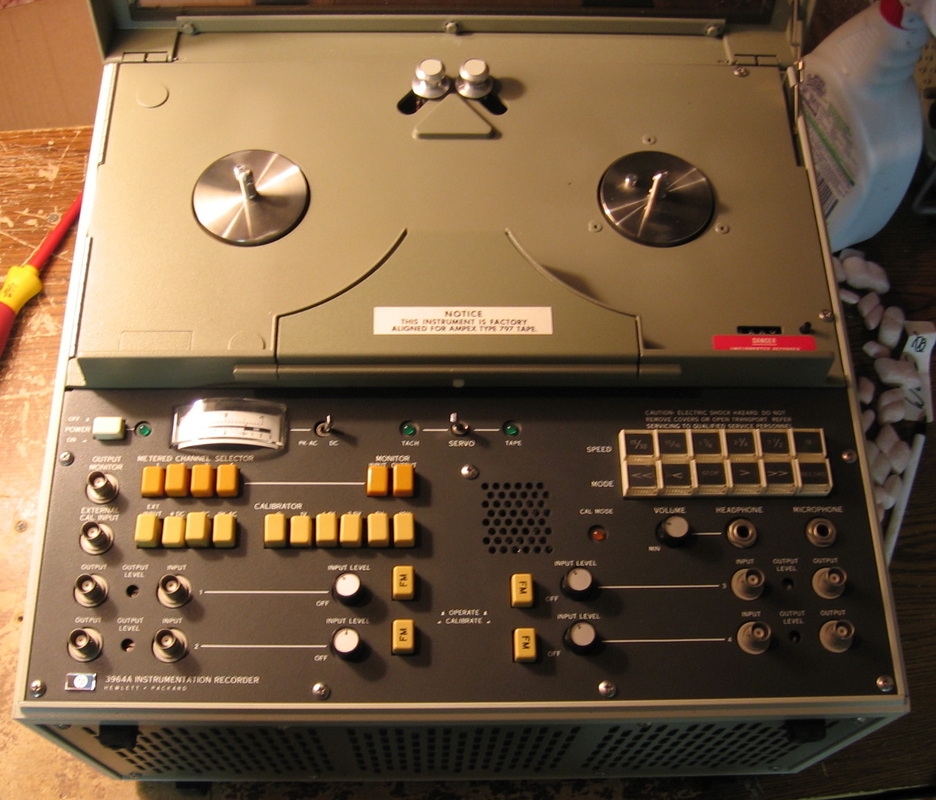
HP 3964A: Four channel instrumentation recorder using 1/4" tape, speed to 15 ips. FM recording DC-3 kHz. I bought this piece shortly after acquiring a Racal 14DS recorder. I guess I was in my "tape recorder phase." My initial thought was to use recorders to instrument test equipment, particularly the Guildline 9577 that was drifting when it warmed up. Never did that however. (OM) Grade: B
No manual for this one. The pinch roller had turned to glop so I had it re-rubberized (Terry's rerubber). But he used the wrong dimensions, so when I received the rebuilt roller, it wasn't hitting the capstan correctly. Fortunately, I figured out how to adjust the mechanics.
Postscript: Came across a recent post from a manual vendor in the Yahoo HP newsgroups in which he was offering to give away the hard-copy manual for the cost of postage. Obviously I jumped all over that. The manual is truly a piece of work - one of HP's best. Now I can run through the performance tests and calibration procedures.

HP 4140B: pA Meter/DC Voltage Source. The HP 4140B is basically a very sensitive ammeter with measurement capability from about 20 mA down to 1 pA, with 1 fA resolution on the 1 pA range. The unit also contains two independent voltage sources (to +/-100 volts) with three digit resolution. The primary voltage source is programmable off the front panel to get a variety of up and down ramps; the secondary voltage source holds a constant value. One measures current by hooking the BNC voltage output jack (either channel) to a DUT and then hooking up the triax input jack in series with that (the triax connector provides an extra guard line). The two voltage sources are convenient when testing semiconductors (one source for the base voltage and one source for the collector voltage). In fact, the HP 4140B is listed in the HP catalog in the semiconductor testing section. While basically used to measure current, the programmable voltage ramps allow the 4140B to measure capacitance, internally calculating it via the equation I = C dV/dt. The measurement accuracy is +/-0.5% for most practical ranges, but starts to degrade at 1E-10 amps and ends up at about +/-5% at the lowest range. The voltage source accuracy is about +/-0.1%. HP sold a couple of special test fixtures for the 4140B (which obviously have vanished off the face of the Earth) that really need to be used at very low currents. Without any of them, my little triax/alligator cable (which came with some HP piece I bought years ago) pretty much limits measurements to about 1E-10 amps. The picture shows the unit supplying 0.12 volts to a resistor I pulled out of a defunct Simpson VOM. The resistor was marked 117.5 Mohms (!!!) and my HP 4329A high resistance meter measured it about 125 Mohms. So I would expect the current to be 0.12/125E6 = 0.96E-9. Close enough. The condition of this unit was not described in the eBay listing, but it had a 2006 Agilent cal sticker on it, the seals were still intact, and the listing photo showed a correct initial display (proving that self-test passed). So I was pretty sure that it would work and I was correct. Other than a quick alignment and cleanup, there wasn't much to do. No real complaints - does exactly what it is supposed to do with minimal fuss. (PDF) Grade: A
Postscript: Preemptively replaced the Rifa 0.22 uF X-capacitor hanging off the power receptacle with a non-Rifa 0.22 uF X-capacitor.
Postscript^2: While responding to a post on eevBlog about the offset on the 1E-12 range, I noticed that my unit read about 0.5x1E-12 after the one hour warmup. I removed the A1 board (I to V converter) and cleaned the board and range resistors with alcohol. Upon reassembly, the offset was down to about 0.05x1E-12 and went to 0.000x1E-12 after I pressed the front panel zero button. Much, much better. I guess years of sitting in a damp, dusty basement produced some leakage paths even though the input components are under a sealed metal cover and looked absolutely pristine to the naked eye.
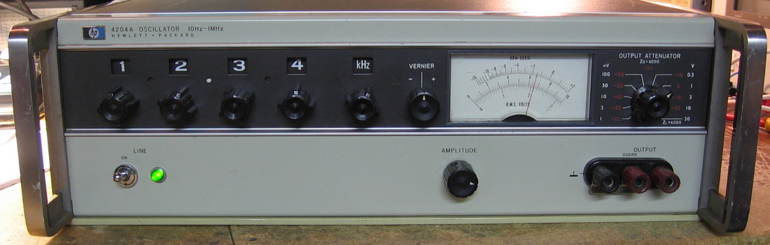
HP 4204A: "Digital" Oscillator from 10 Hz to 999.9 kHz, 10 volts into 600 ohms, 80 dB amplitude range. Introduced in 1967, HP called this a digital oscillator even though it is entirely an analog unit. The frequencies are selected by four 0-9 digit knobs which can select 39,600 resistor combinations in the feedback loop of a Wien oscillator. Frequency accuracy is +/-0.2% and repeatability is +/-0.01%. Mine has a distortion at 1 kHz of about 0.2%. Designed and built by HP-Japan (Yokogawa), the Japanese must have been trying to impress mother-HP because the build quality is superb. The frequency selection switches look sort of like the turret of a revolver pistol. As the knob is turned, the proper resistor rotates into position and makes contact with leaf springs on the bottom of the switch. (PDF) Grade: B+
The unit produced no output on arrival because the switch assembly needed cleaning. But the cleaning was trivial because I only needed to dab a little alcohol on the leads of the resistors that make the contact with the springs. The switch, properly cleaned, should last forever. The NE-2 bulb was burned out, so I replaced it with an LED dropped down from the 36V supply. And while I was poking around, I inadvertently shorted a couple of pins on the P/S edge connector and managed to put 60V forward bias across a Zener (with no real current limiting): poof.
The unit produced no output on arrival because the switch assembly needed cleaning. But the cleaning was trivial because I only needed to dab a little alcohol on the leads of the resistors that make the contact with the springs. The switch, properly cleaned, should last forever. The NE-2 bulb was burned out, so I replaced it with an LED dropped down from the 36V supply. And while I was poking around, I inadvertently shorted a couple of pins on the P/S edge connector and managed to put 60V forward bias across a Zener (with no real current limiting): poof.
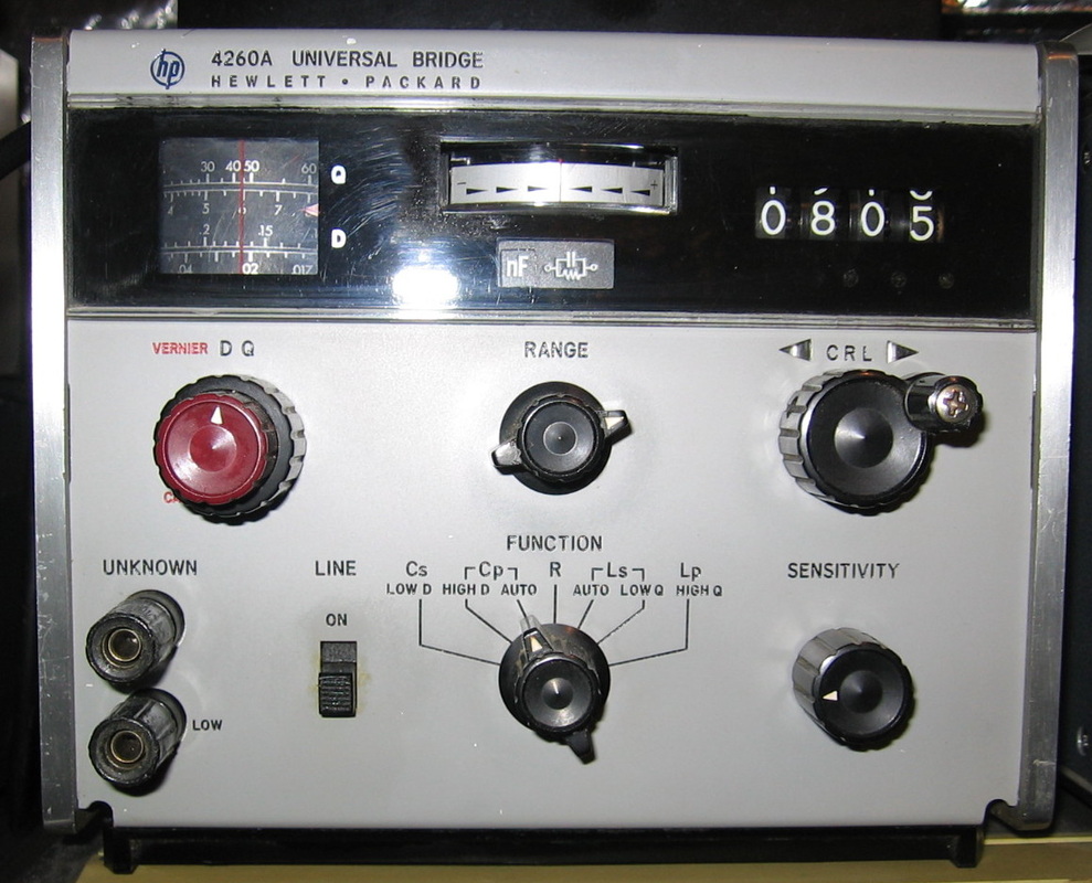
HP 4260A: Universal bridge for those who couldn't afford an HP 4262A. Sort of a pain to use like all bridges. This was built by HP-Japan and is very nicely done, with electrolytic capacitors cradled in their own little plastic buttresses. (PDF) Grade: B
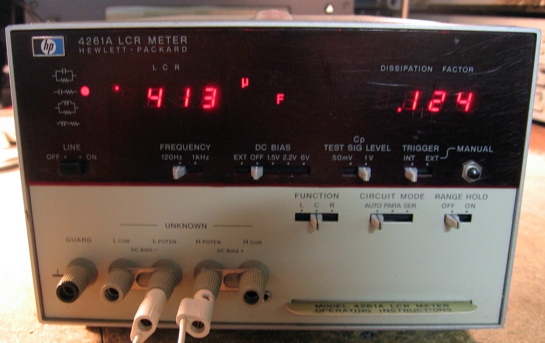
HP 4261A: LCR meter. A junior version of the HP 4262A, it has 120 Hz and 1 kHz measuring frequencies. The right-hand display only does dissipation, so you need to have a calculator handy if you want to derive the parameters that the HP 4262A or HP 4274A can show you. The basic accuracy is about 0.2%. Straightforward to use. (PDF) Grade: A-
The eBay photo showed random garbled characters on both displays. And that's the norm for a fraction of a second when the unit first powers up. But my unit was totally stuck and not stepping through the algorithmic state machine. The state machine is ROM-based and a pal at work had a similar problem where the latch/counter holding the program address and feeding the ROM was faulty. So that's the first place I looked. The relevant chips were a pair of 74C163s and both were in sockets. Funny how the only chips (other than the ROMs) in the 4261A that were socketed were these two. And even funnier is that the sockets are not shown in the manual (although I don't have all the change sheets). What isn't at all funny is that the chips were marked National Semiconductor. Yet another example of the absolutely atrocious quality of National Semi parts (see my rant on the HP 3581C). The sockets definitely were original, not a later rework. Anyway, two new 74C163s solved the problem and the unit works fine. The only other problem was a cracked banana jack on the front panel. I was going to leave it alone since it was being held in place by the shorting bars, but there was a ground ring with protection diodes attached that wasn't making good contact with the chassis as a result of the breakage, so I ended up replacing the connector. Also replaced the Rifa suppression cap with a non-Rifa brand.
The eBay photo showed random garbled characters on both displays. And that's the norm for a fraction of a second when the unit first powers up. But my unit was totally stuck and not stepping through the algorithmic state machine. The state machine is ROM-based and a pal at work had a similar problem where the latch/counter holding the program address and feeding the ROM was faulty. So that's the first place I looked. The relevant chips were a pair of 74C163s and both were in sockets. Funny how the only chips (other than the ROMs) in the 4261A that were socketed were these two. And even funnier is that the sockets are not shown in the manual (although I don't have all the change sheets). What isn't at all funny is that the chips were marked National Semiconductor. Yet another example of the absolutely atrocious quality of National Semi parts (see my rant on the HP 3581C). The sockets definitely were original, not a later rework. Anyway, two new 74C163s solved the problem and the unit works fine. The only other problem was a cracked banana jack on the front panel. I was going to leave it alone since it was being held in place by the shorting bars, but there was a ground ring with protection diodes attached that wasn't making good contact with the chassis as a result of the breakage, so I ended up replacing the connector. Also replaced the Rifa suppression cap with a non-Rifa brand.
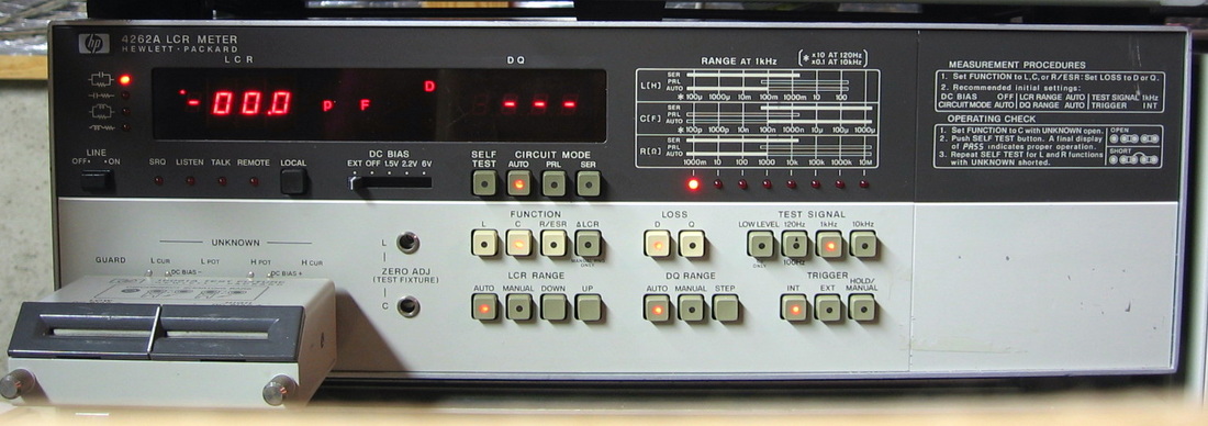
HP 4262A: LCR meter with test fixture. All automatic (but manual override possible). Just insert the component and read the numbers. It's certainly much easier to use this than the HP 4260A, the GR 1685B or just about anything else. And that's why the other pieces are collecting dust. (PDF) Grade: A
I have been using this piece for many years until one day, about 10 minutes after it was first powered up, I heard a loud pop followed by the unmistakable stench of a burned Rifa suppression capacitor. It was duly replaced with a non-Rifa brand after I cleaned up the goo that had been spattered all around inside.
I have been using this piece for many years until one day, about 10 minutes after it was first powered up, I heard a loud pop followed by the unmistakable stench of a burned Rifa suppression capacitor. It was duly replaced with a non-Rifa brand after I cleaned up the goo that had been spattered all around inside.
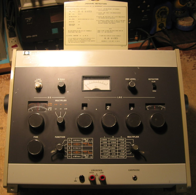
HP 4265B: Universal Bridge. This is another entry in a set of LCR meters manufactured by HP-Japan. It is a little more cumbersome to use than the semi-automatic HP 4260A bridge that I also have; it is more in line with my Beco 815-AF. It boasts a basic accuracy of 0.2% which is quite good. But unlike all of these bridges, why would I ever want to use this when I have fully automatic LCR meters? I think you know the answer to that question. The 4265B is built like a tank. The potentiometers are huge, the wafer switches are huge, and the three numeric dials
have switches behind them that I have never seen before. They are in clear sealed plastic cases and have a set of what look like relay contacts that are opened by rotating concentric plastic discs with tabs in them. (PDF) Grade: B
There was nothing electrically wrong with the unit. But the mechanical side was a mess with cracked knobs, hard to turn controls, etc. The function control shaft was seized and took a Vise-Grips and some WD-40 to free it up.
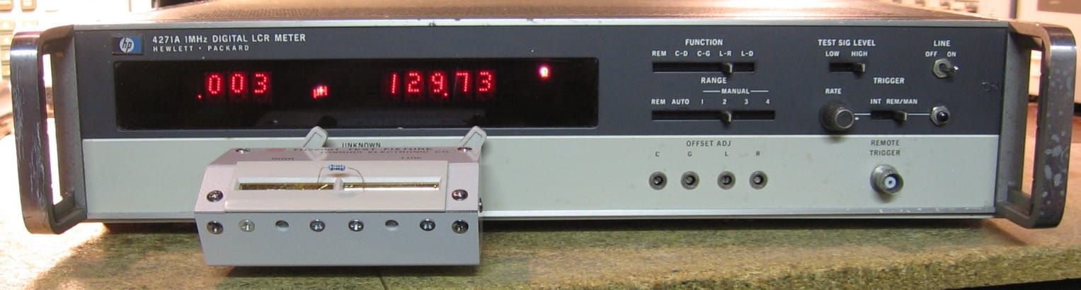
HP 4271A: 1 MHz LCR meter. Measures 1) Capacitance/Dissipation, 2) Capacitance/Conductance, 3) Inductance/Resistance and 4) Inductance/Dissipation. Being that it is at 1 MHz, it will only go to 19 nF, 19 Kohms and 1.9 uH respectively with best-case accuracies approacing 0.1%. Uses the same 4-BNC Kelvin arrangement as in my HP 4274A and thus I can also use the Chinese clone test fixture I bought for the 4274A on this piece. My unit has the internal bias option, not that I can use it. For HP requires you to control the internal bias card with an external "digital" controller, e.g. HP 16023A. Mine also has a couple of digital input/output options and connectors. All this was prior to HPIB which HP eventually included when they went from the "A" model to the "B" model. Very easy to use (much easier than my HP 4280A 1 MHz C/V machine), but I hate the clunky slide switches. Build quality is superb for a mid-1970's piece and HP went the extra effort to include not one, but two extender boards. ($CD) Grade: A-
Advertised by the seller as for repair with a tag that says "broken power switch." OK, easy enough to fix that. But when it arrived, the tag said "broken function switch," and that's a whole different story. Turns out the function slide switch was fine, but the connector from the switch board to the motherboard was faulty. The connection to the switch board is made with a thin plastic flex-cable that is merely laid on top of the board edge pins and held there by a metal strip that is screwed into the board on each end. Works great as long as that metal strip is perfectly straight and flat - which mine wasn't. After I straightened it out so all the connections were actually made, the function switch worked fine. The only other problem was a missing dot in the "1" of the most significant digit on the right display. The LEDs used in this piece are the 1990-0329 versions which pre-date modern alphanumeric LEDs. These accept BCD inputs and have a latch and decoder built into the LED. So if one of the dots is missing, it is not likely an external connection problem. I took the soldering iron and heated up all the pins in hopes of shaking something up (or re-bonding something internally). Apparently, that worked since my missing dot is gone. There were a couple of 5V incandescent bulbs blown so I replaced all 16 with LEDs - this required changing a bunch of current limiting resistors on the display controller boards. Finally, I would like to run through the calibration procedure, but good luck. The manual calls for a bunch of standard C's and L's that I don't have.
Postscript: Turned it on one day and one of the digits was stuck at "----". I ordered two used LEDs from eBay and one of the two actually worked (the other one was missing the top and bottom rows) and so it replaced the stuck digit.
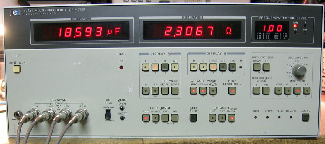
HP 4274A: Multi-frequency LCR meter. This piece is the big brother to the HP 4262A (see above). Not only can it do more measurements (C, L, R, Z, D, Q, ESR, G, X, B, theta, deviation, %deviation), but it can do them at a choice of 11 different frequencies from 100 Hz to 100 kHz and with a continuous range of test voltages up to 5 volts. Mine does not have the internal DC bias option, but biases can be added externally through a back panel jack. The accuracy is on the order of 0.1%, but that is best case. The manual devotes more than 5 pages to completely specify the accuracy among the various ranges. Like the HP 4262A, it is pretty much plug-and-play. But as with all better LCR meters, you sort of have to know the approximate answer before you start because it is easy to select a frequency, voltage, or mode where you can get an erroneous reading. Unlike the 4262A which uses banana jacks in a 4-wire configuration, the 4274A uses four BNC cables to carry the Kelvin arrangement. However, unlike most Kelvin clips, the outer shields of the four BNC cables have to be tied together at the DUT. So I took the Kelvin set I was using with my ESI SP5110 LCR meter, scraped away the outer jacket and tied all the grounds. This is quite annoying so I have on order a Chinese clone of the test fixture one normally uses with the 4274A. The HP 4274A was my 300th piece!!! And so I splurged a bit and spent $250 for it. (PDF) Grade: A
I took a chance on this piece because the seller advertised it as not working and throwing errors. Upon receipt, all the P/S voltages were correct, but the unit was unresponsive to any resistors, capacitors or inductors. Moreover, the series and parallel LEDs were alternately flashing like the unit was trying to make up its mind. Most of the front panel button presses did nothing, as if the unit was still in the process of making a measurement. So I decided to run the self-test which consists of 23 separate sub-tests. The thing failed all 23 of them. I figured that each test was making some sort of measurement and thus the only way every test failed was if the A/D board was bad. And so it was, since after hours of marching through the service manual's diagnostic charts, I arrived at an LM361 comparator that tells the unit when the digitizer has finished. The LM361 output was stuck high which explains why the unit was essentially non-responsive. Turns out that my HP 5335A counter has such a part (and I have a spare HP 5335A), so I ripped it out and installed it into the 4274A. The thing sprang to life and started to make reasonable measurements. However, I discovered that the some of the self-tests still failed, but only at specific frequency settings like 2 kHz and 40 kHz. Moreover, while most component measurements were accurate, there were ranges (2 uF to 5 uF) where the 4274A was pretty much out to lunch. I grappled with this for a day trying to put my finger on whether something was really wrong or it was some strange resonance with my modified Kelvin clips. After getting nowhere fast, I decided to run through the adjustment procedure. At one point, you are supposed to adjust a pot to get two test points 90 degrees out of phase. My two test points read close to zero degrees and the pot had no effect. Great, another diagnostic chart to work through. It led me to an MC1458 dual op-amp whose input and output voltages weren't even close to being right. I pulled the op-amp and installed an LM833 from the junk-box. Now, all 23 self-tests pass in all 11 frequencies and I'm not getting strange behavior with 2-5 uF caps. The only other repair was one of the front-panel LEDs that was dark. I put 10 mA through the LED and it lit, and all the control signals (which are multiplexed) seemed OK, so I scratched my head and just touched up the solder joints - voila.
Postscript: One day I turned on the unit and it was completely dead. One side of the DPDT power switched had opened up. It was suitably replaced, which took a bit of fiddling since the new switch had slightly different dimensions. A post-mortem of the old switch showed a nice lump of carbon fused onto one of the contacts.
Postscript^2: Preemptively replaced the Rifa 0.22 uF X-capacitors in the P/S with non-Rifa 0.22 uF X-capacitors.
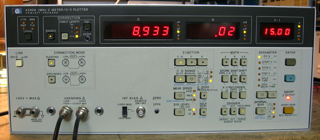
HP 4280A: 1 MHz C Meter/C-V Plotter. As the HP brochure says, "fast, high resolution capacitance and conductance testing with built-in staircase and pulsed bias." And that's about the only sentence in the brochure I understand - the rest is pretty much incomprehensible. The 4280A was usually sold as part of a multi-piece HP 4062B Semiconductor DC Parametric Set, but it stands on its own for basic capacitance testing. Because of the 1 MHz measurement frequency, the 4280A will only go up to about 1900 pF, so you ain't gonna be testing power supply electrolytics with this puppy. As the brochure says, you can give it a variety of voltage ramps and plot the results out on an external plotter. Similarly, you can twang a capacitor with a pulse and make a voltage vs. time plot. Shown in the picture is a measurement of a varactor's capacitance with 15V back bias. The basic accuracy is in the 0.1% class which is good, but not super-good. However, one look at the front panel shows that there are a lot of wonderful things being done somewhere. On the other hand, I have to deduct points for an overly confusing front panel. But the build quality is simply outstanding, even better than most other HP pieces (this one was made by Japan's HP-Yokogawa). This unit came with a 2007 Agilent calibration sticker and seals on the covers. I can only hope that means it is working properly. While I do have an op manual and a sparse service manual, the troubleshooting section was placed in its own separate manual. Good luck finding that. (PDF) Grade: A-
Postscript: Preemptively replaced the Rifa 0.015 uF Y-capacitors in the power supply with non-Rifa 0.01 uF Y-capacitors.
Postscript: Preemptively replaced the Rifa 0.015 uF Y-capacitors in the power supply with non-Rifa 0.01 uF Y-capacitors.

HP 4282A: High capacitance meter ranging from 10 nF to 1 F full scale. Selectable measuring frequencies of 120, 100 and 60 Hz, DC bias to 100 V. Also measures D and ESR, however HP tried (and failed) to introduce a new measurement unit, ohms-farad, for ESR that requires the user to divide by the capacitance to obtain the true ESR reading. My unit has Option 001 which will measure the leakage current after the capacitor is charged. The basic accuracy is about 1%. Very simple to use and a good adjunct to my other LCR meters which top out at about 20,000 uF. (PDF) Grade: A
The unit as received had several faults. There were three electrolytics from the same manufacturer that were highly suspect. One measured OK, but one was leaking and one had separated from one of its leads. All three were replaced. The DC bias front panel switch was faulty and was replaced. The unit uses about 18 T-1 incandescent bulbs and about 1/3 of them had burned out. All 18 were replaced with LEDs and some resistors were changed to set the proper current. The Option 001 board had a burned out 1K, 2W resistor and there was a lot of charring on the board underneath. This resistor was replaced with a 3W version and lifted off of the board. The front panel input connector is a 4 pin Amphenol-like piece, but I could not find a suitable part number and rather than guess at what I would have needed for a plug, I removed the connector and bought a matching plug and jack. As shown in the photo, the cable terminates in four banana plugs. This allows me to use the Kelvin clips I made for the HP 4328A as well as to disconnect the two voltage sense leads when I need to make a leakage measurement (per the manual).
The unit as received had several faults. There were three electrolytics from the same manufacturer that were highly suspect. One measured OK, but one was leaking and one had separated from one of its leads. All three were replaced. The DC bias front panel switch was faulty and was replaced. The unit uses about 18 T-1 incandescent bulbs and about 1/3 of them had burned out. All 18 were replaced with LEDs and some resistors were changed to set the proper current. The Option 001 board had a burned out 1K, 2W resistor and there was a lot of charring on the board underneath. This resistor was replaced with a 3W version and lifted off of the board. The front panel input connector is a 4 pin Amphenol-like piece, but I could not find a suitable part number and rather than guess at what I would have needed for a plug, I removed the connector and bought a matching plug and jack. As shown in the photo, the cable terminates in four banana plugs. This allows me to use the Kelvin clips I made for the HP 4328A as well as to disconnect the two voltage sense leads when I need to make a leakage measurement (per the manual).

HP 4328A: Low resistance meter from 100 ohms down to 1 milliohm full-scale. Seeing as I already had the high resistance meter (HP 4329A), I had to have this piece also. Uses a 4-wire measurement technique, but unlike regular ohmmeters, whose ability to measure very low resistances is compromised by the minute induced DC voltages from the galvanic reaction of the test leads with the DUT, the 4329A uses a 1 kHz AC measurement. Shown in the picture measuring 1.6 ohms internal resistance of a weak 9V battery (try that measurement with a standard VOM!). Fairly accurate as far as I can tell, except in the lower 1/4 of the range. But since it uses a 1-3-10 range scale, one should never be operating less than 1/4-full scale anyway. (PDF) Grade: A
The unit came with Option 001 (battery) and without the Kelvin leads. The batteries, ca 1985, hadn't leaked (what a pleasant surprise) and still held a charge. But the unit won't work with a discharged battery, even off of AC, and I'll never use it enough to keep the batteries charged, so I gutted the P/S board, threw two 7815 regulators in there, and converted the unit permanently to AC power. For the test leads, I purchased the proper male connector and a set of Kelvin clips. The leads actually run first to banana plugs so I can use Kelvin clips, banana-to-minigrabber leads, or whatever else I decide to use in the future, without disturbing the main cable and connector to the unit. The only other electrical problem came when I was doing the alignment. I needed to change one factory-selected resistor in order to improve the linearity of the meter.
The unit came with Option 001 (battery) and without the Kelvin leads. The batteries, ca 1985, hadn't leaked (what a pleasant surprise) and still held a charge. But the unit won't work with a discharged battery, even off of AC, and I'll never use it enough to keep the batteries charged, so I gutted the P/S board, threw two 7815 regulators in there, and converted the unit permanently to AC power. For the test leads, I purchased the proper male connector and a set of Kelvin clips. The leads actually run first to banana plugs so I can use Kelvin clips, banana-to-minigrabber leads, or whatever else I decide to use in the future, without disturbing the main cable and connector to the unit. The only other electrical problem came when I was doing the alignment. I needed to change one factory-selected resistor in order to improve the linearity of the meter.
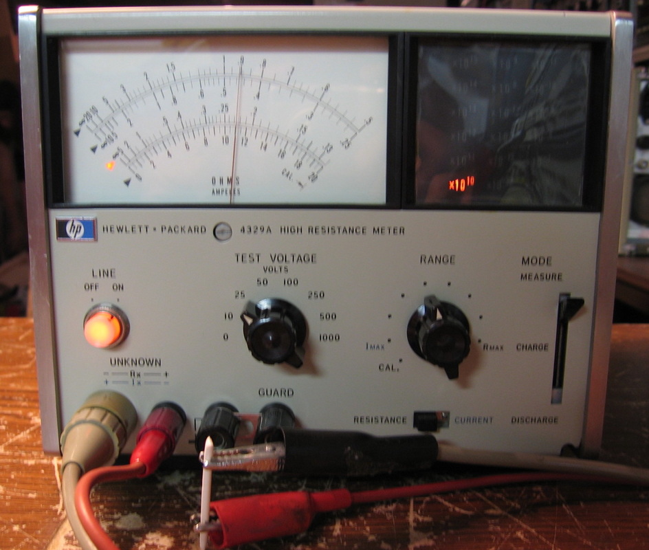
HP 4329A: High resistance meter from 500K to 2x10E16 ohms. Also functions as a pico-ammeter. Shown here measuring a few billion ohms resistance of a piece of a Q-tip. I don't often need to measure the resistance of a Q-tip, but when I do, I've got the piece that will do it! Seriously, I have used this to measure some of the stupidly high resistors in the Simpson and Triplett VOMs. (PDF) Grade: A-
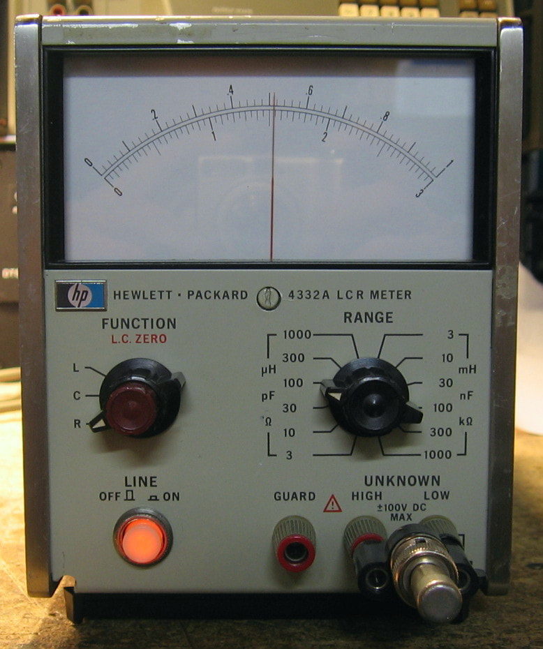
HP 4332A: Analog LCR meter. The 4332A measures inductance, capacitance and resistance in 12 ranges on a 1-3-10 scale. The full-scale ranges are 3uH - 1H, 3pF - 1uF and 3 ohms - 1000 ohms. The series-parallel selection and AC measurement frequencies are pre-ordained by the unit (L-series, C-parallel, R-series at 1 kHz or 100 kHz). By the time you add up all the accuracy specs, the basic conclusion is about 2.5%. Measurements are done with a two-terminal arrangement, however there is a third guard terminal which really needs to be used, for instance, at high resistance measurements. Nowhere as good as the digital LCR meters (e.g., HP 4262A or HP 4274A), but the small size makes it very convenient for a quick measurement. ($CD) Grade: A- (see Postscript below)
Postscript: I made up a set of test leads which makes the 4332A so much better at both extremes of the ranges. The High and Guard terminals go through a banana plug to BNC adapter. The other end of the BNC cable has the shield clipped at the end and the inner terminal to an alligator clip. The Low terminal uses a banana plug to a wire to another alligator clip, with the wire simply loosely wrapped around the High/Guard coax. I've now bumped up my previous grade of B+ to an A-.
Upon receipt, the 4332A almost worked. Many of the ranges were spot on, but there were others where it was flaky. For instance, the meter is supposed to read zero for a C measurement with the input open (and there is a zero pot on the front panel for fine adjustment). But mine was reading about 40 pF and couldn't be zeroed. The upper R scales were also gyrating a bit. I bought the manual (the on-line free version was unreadable) and a few days later settled down for a nice troubleshooting session. While I was getting the scopes and voltmeters set up, the 4332A settled down and all the problems disappeared. I went through the calibration procedure and all the adjustments worked as expected. This may have been another instance of a dormant piece needing a few hours to reform the capacitors. All that was left was to replace the burned out neon bulb in the power switch. But HP used a strange switch where I have no idea how to remove the neon bulb without destroying the switch button. So I simply exchanged the entire switch with the more standard version found in my pile of defunct HP parts.
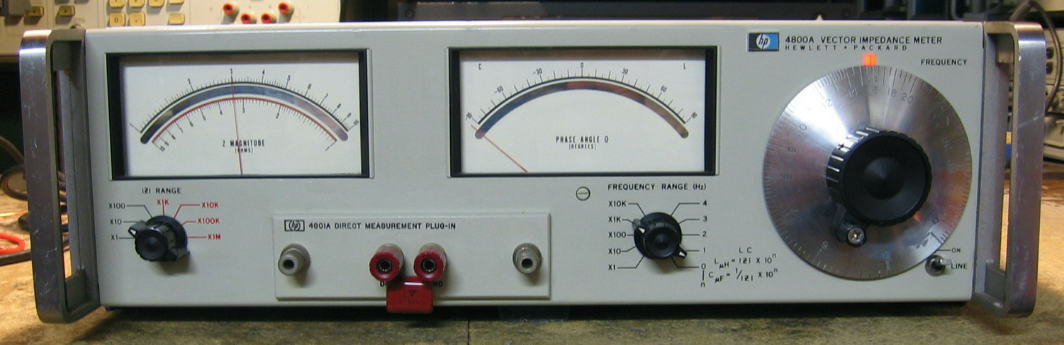
HP 4800A: Vector impedance meter, good to 500 kHz. Hook up to the front panel jacks and measure the magnitude and phase of the (complex) impedance - that's pretty much it. The accuracy is not particularly good, about 2% for magnitude and +/-6 degrees for phase. Of course, it is left up to the user to translate impedance into a component's value (for example, inductors or capacitors). However, if you look carefully at the main frequency tuning knob, you will see a little mark labeled "LC" at 15.92. Now look left of the tuning dial and you will see two formulas for L and C. When the tuning knob is set at 15.92, these formulas provide the component value. For example, the picture shows a capacitor that gives an impedance of -30j ohms (the phase angle should be exactly -90, but it is good enough). The frequency range knob is pointing to 1, so the formula to use is C(uF) = 1/30 x 10^1 = 0.33 uF. And since the capacitor was marked "334", that's exactly right. Even though I've already quoted the basic magnitude and phase accuracies, the calculations of component values, when done as just described, is only about 7%. Given that all this thing is doing is running an oscillator through a DUT and measuring the voltage and current, I'm not at all clear why HP took 20 circuit boards to do that. Moreover, one of the detectors uses a sealed light/photodetector unit which will take a bit of experimentation when the bulb finally burns out. And you really have to be careful with components hooked up via test leads to the front panel jacks - the inductance and capacitance of your test leads are perfectly happy to screw with the complex impedance and the 4800A is perfectly happy to display it to you. This piece was my second attempt at an HP 4800A. The first one (see the "It's Dead, Jim" section below) was unrepairable; this one was in excellent shape and looks like at least the cabinet and front panel were professionally restored. (PDF) Grade: B
This piece was advertised in condition unknown, but basically worked upon receipt. It was, however, quite a bit out of adjustment and required changing one factory-selected resistor. And then after a day, the thing acted flaky, which was boiled down to a faulty A7 Schmitt Trigger board. The previous repairman had already replaced the six transistors on the board, and if he could, then so could I. After replacement, the unit was much better, but the phase alignment is very touchy and ends up being a compromise across all frequencies and impedance ranges.
Postscript: After some more playing around with this unit, I noticed that it takes about one hour to achieve accurate readings. A quick check of the source oscillator output showed that it was not oscillating correctly during this warm-up period. Really the only thing that could account for this is the light bulb(s) in the feedback of the Wien oscillator circuitry - a special HP sealed unit containing three incandescent bulbs. The ohmmeter showed that the bulbs were not open, but something was definitely wrong. I noticed that if I touched a soldering iron to the three connection points on the board, the oscillation immediately began. HP describes the innards of this bulb set twice in the manual - and the descriptions do not agree. At one point, they talk of a 3V bulb and at another a 10V bulb. I pulled the sealed unit out and experimented with a variety of discrete bulbs. However, while this cured the lack of oscillation during warm-up, I could not achieve oscillation across all frequencies with the limited variety of bulbs in my junkbox. Luckily, an e-Bay seller had a new old stock unit. Unluckily, he wanted $50 for it. We compromised at $35, which is still outrageous for three incandescent bulbs, but when you need something, you need it. And that cured the problems with the HP 4800A.
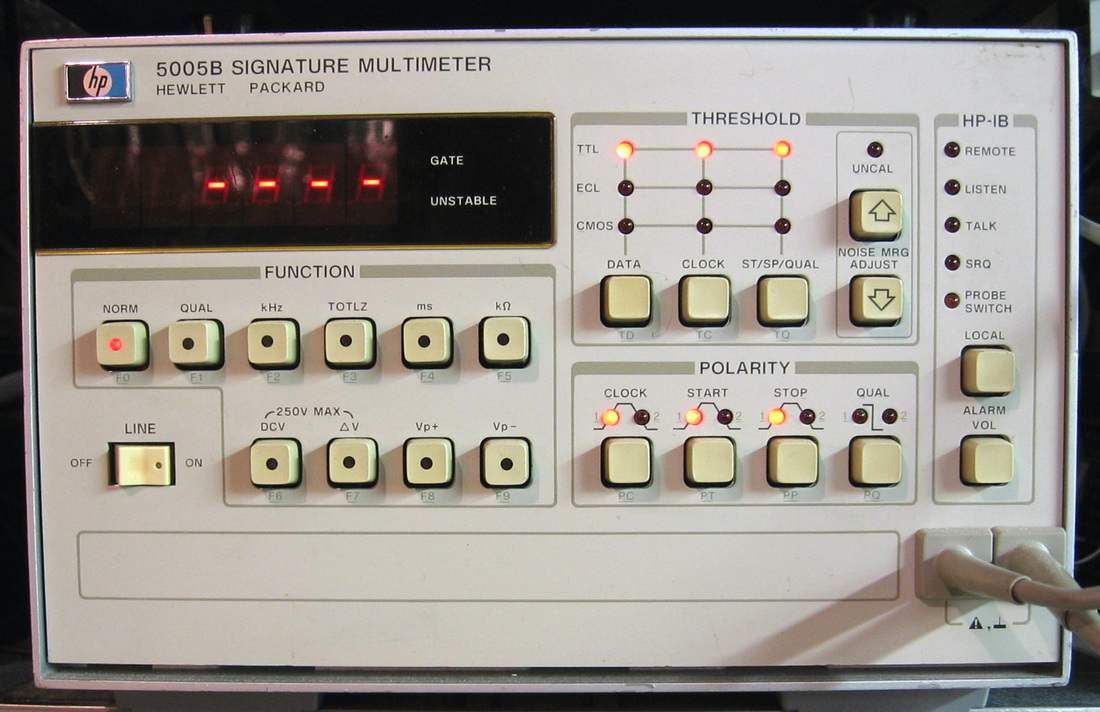
HP 5005B: Called a signature multimeter, this is a combination of a signature analyzer, a counter, a voltmeter and an ohmmeter. A "one instrument does all." Has presets for TTL, ECL, CMOS. See the comments for the HP 5006A below. (PDF) Grade: A-
Upon boot up, just hung. Great. The extensive "diagnostics" are available if you have an HP-IB connection. But what happens if the HP-IB isn't working? That was exactly the case. Through trial and error, I fixed this unit by replacing the RAM on the HP-IB board. I also rebuilt the probe by salvaging parts from an old HP pulser.
Postsciprt: Preemptively replaced the two Rifa 2200 pF Y-capacitors in the power supply with non-Rifa 1500 pF Y-capacitors.
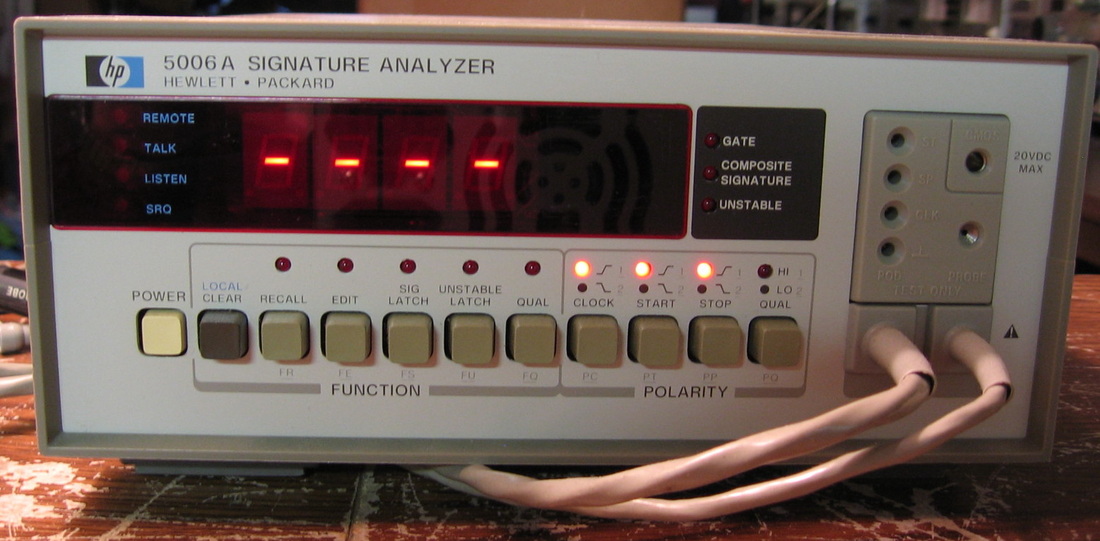
HP 5006A: Signature Analyzer. Used to debug most HP instruments of the 1980's. Put the DUT in its diagnostic mode and read the 4 character signature at various IC pins with this meter. Then compare to published HP values. HP and other manufacturers went through a phase when signature analysis was the preferred diagnostic method. You then need to know nothing at all about electronics to debug digital logic - just read the signatures. However, since most of the pieces under test used microprocessors and programs stored in ROMs, heaven help you if your service manual doesn't correspond to the program version in your ROMs. HP updated their ROMs a lot. I don't think I ever found a bad IC using signature analysis. All I really did was prove that the digital side of some piece was working correctly and that the problem was elsewhere. (PDF) Grade: B+
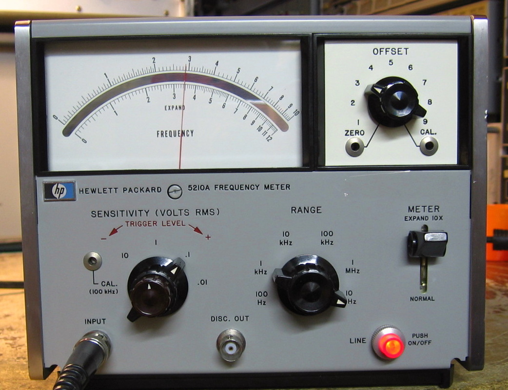
HP 5210A: An analog frequency meter from the late 1960s. Shown here measuring a 3.333 MHz signal using the x10 expand mode option. One reads the leading digit (3) from the offset switch and the rest of the digits (3.47) from the lower meter scale; thus the reading is 3.347 MHz. The difference, 14 kHz, is well within the 30 kHz spec (+/-0.3% of full scale). I suppose this thing has its uses, particularly in measuring FM deviation via the filtered discriminator output jacks, but it's like I'm standing in a room full of people where someone tells a joke and I'm the only one who doesn't get it. Nothing to repair on this one - the insides were just as clean as the outside. (PDF) Grade: B
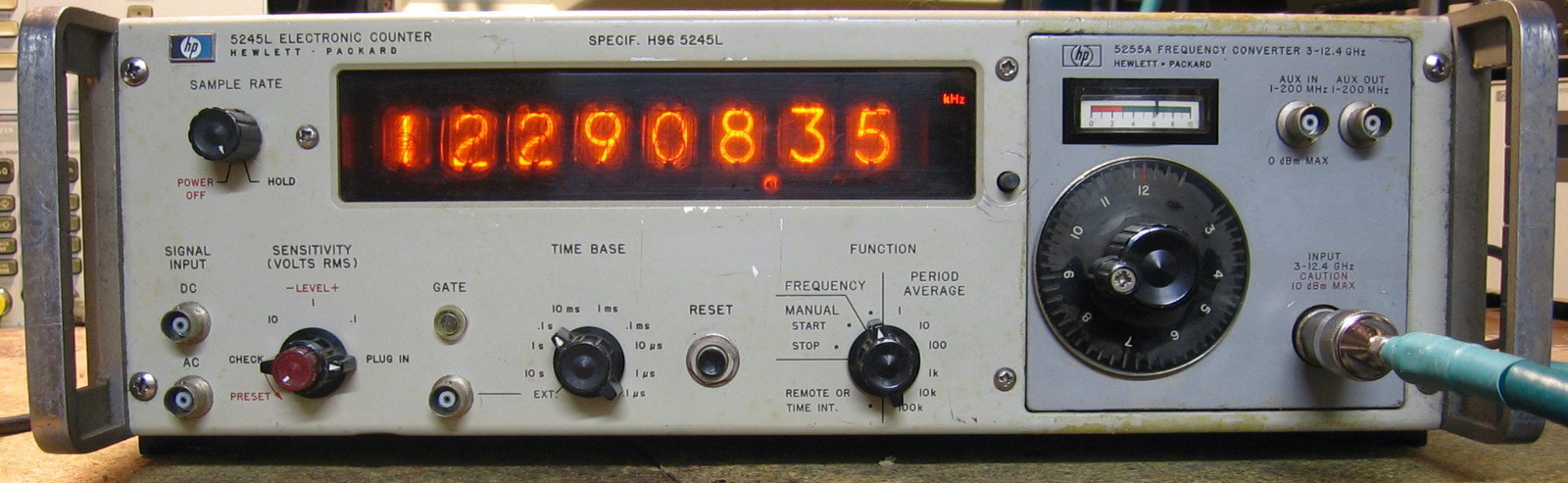
HP 5245L: The HP 5245L counter is a nostalgic 50 year-old piece capable of measuring frequency to 50 MHz and the average period of signals <300 kHz. It contains a 1 MHz OCXO that is multiplied up to 10 MHz. Gate times are selectable as 10, 1, 0.1, etc and period averages use x1, x10, x100 etc. Three selectable sensitivity ranges round out the permissible controls (100 mV basic sensitivity). As is typical of all HP pieces, it comfortably exceeds specs and will count a 73 MHz signal. Has separate jacks for AC or DC coupling and a switch on the rear panel to select whether you want to see the nixie tube digits count up during each gate or be held in "memory" until the next update. Priced at $3,200 in 1962! Postscript: Since the counter was free, I upgraded by purchasing an HP 5253B frequency converter. This plug-in mixes signals in the range of 50-500 MHz down to a 10 MHz baseband where the 5245L can count. Merely add the counter displayed frequency to the frequency dialed in on the plug-in. Pictured measuring a 492.35 MHz signal at 10 mV. (PDF) Grade: B
Postscript: Purchased ($35) an HP 5255A converter which does 3 GHz to 12 GHz, an improvement over the HP 5253B which only goes to 500 MHz. The picture now shows the 5245L with the 5255A converter (with a 12.123 GHz signal input). The 5255A is a bit restrictive and likes to see signals in the -10 to +10 dBm range. It also has a 200 MHz input which goes through an internal 4:1 prescaler for display on the 5245L. Fortunately the 5255A worked right out of the box.
When I pulled this out of the box, something didn't look right. Maybe it was because I purchased an HP 5345 counter from the eBay seller, not an HP 5245L counter like I was now staring at. The seller promptly apologized, realized he no longer had an HP 5345 counter to send me and refunded my money in full. Oh, and he said I could keep the 5245L counter and do with it what I wanted. Well, I wanted to fix it. But other than a flaky neon bulb used in a photodetector circuit to drive the nixie tubes, everything works fine. The NE-81 was replaced courtesy of NormanLamps, but it was a difficult operation.
Postscript: Here's a strange one. After many years, turned on the counter and everything worked perfectly except on the period measurement with the 0.1 usec gate time (the counter just sits there idle). In order to measure at this gate time, the standard internal 1 MHz reference oscillator goes through a x10 multiplier board. The last transistor on the board is an amplifier and it appeared that it wasn't amplifying as promised. It is a germanium PNP 2N2048 and who has any of those in their stash? So I popped in a 2N3906 expecting that it wouldn't work due to incorrect biasing. But lo and behold, all fixed! Afterwards, I put the old 2N2048 on a breadboard, wired it up as a common emitter amplifier and measured the voltage gain at about x5 (whereas the 2N3906 measured a gain of about x45). So the transistor definitely had lost its oomph.
Postscript^2: The 5245L is nearing the end of its 50+ year life. The counter can operate in storage and non-storage modes (selectable by a rear panel switch). In storage mode, the display updates at the end of the count cycle (gate); in non-storage mode, you see the digits flashing continuously as the count proceeds. When using the storage mode, the first two digits sometimes do not show the correct number and sometimes they do. This is probably due to weak NE-81 bulbs or weak germanium driving transistors. Since there are 64 bulbs and 64 germanium transistors for the combined 8 digits, I'm not about to replace them. And the counter operates flawlessly in non-storage mode, so I will simply use that mode.
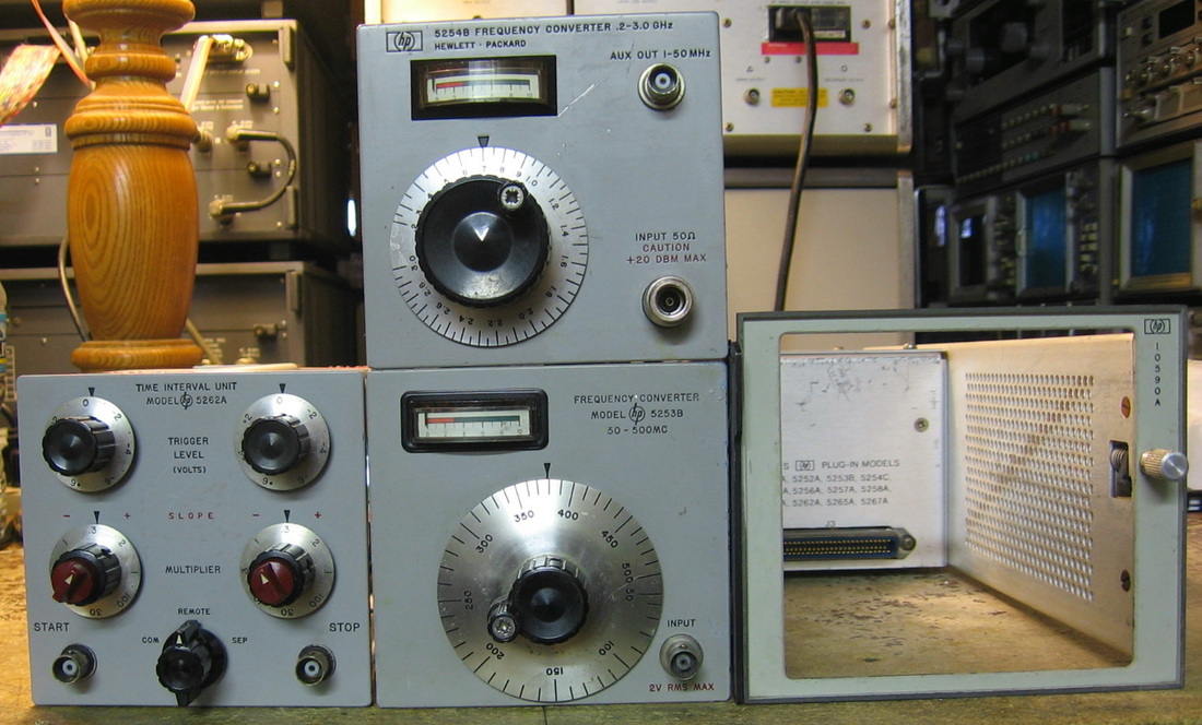
HP 5253B, 5254B, 5262A, 10590A: These are plug-ins for the HP 5245L and HP 5345A counters. The 5253B is a frequency heterodyner that mixes 50-500 MHz down to baseband in 10 MHz chunks. The 5254B mixes 0.2-3 GHz down to baseband in 50 MHz chunks. The 5262A is a time interval counter that produces a start/stop trigger for signals up to 1 MHz. As the 5245L counter is a 50 MHz unit, all three of these plug-ins work fine in the 5245L. When HP later came out with the 5345A counter, they realized people might still want to use the old plug-ins. So they designed the HP 10590A adapter which adapts these early plug-ins to the 5345A. (PDF) Grade: B
Postscript: I now also have the HP 10539A adapter which allows 5245 counter plug-ins (not the 5262A however) to be used with the HP 5360A counter.
Postscript^2: Added an HP 5255A 12 GHz heterodyner to the collection. See the entry for the HP 5245L counter above for a picture.
There was nothing wrong electrically with any of these pieces. However, due to their age (up to 50 years), all the mechanical parts had pretty much frozen. Not usually a problem, except the 5253B/5254B use tuned cavities and these required disassembly, cleaning, reassembly and realignment (with no published alignment procedure). HP warns in their manual that the cavities are not field repairable, but I took that as a personal insult.
Postscript: One day I noticed that the HP 5253B that I installed in the HP 5360A counter was not working; seemed totally dead. That usually indicates a power supply problem and a few measurements isolated it down to the 20V supply that is created in the HP 10539A adapter from the 24V furnished by the 5360A counter. The 2N3053 pass transistor tested faulty and was replaced with a 2N2219A. When I tuned everything back on, the 2N2219A immediately blew. So did a second one that I tried. I had noticed that the 22 uF electrolytic capacitor hanging off the output of the pass transistor had a DC resistance of about 660 ohms. I really didn't think that was of any concern. But an ohmmeter measures resistance with a much lower voltage and current than the pass transistor circuit is supplying. When I pulled out the cap and hooked it up on the bench to an external supply at 20V, it immediately forced the power supply into its max current limit of 1.7A. So no wonder this faulty cap kept popping my pass transistors. A new cap (and a third 2N2219A) fixed the 10539A adapter.
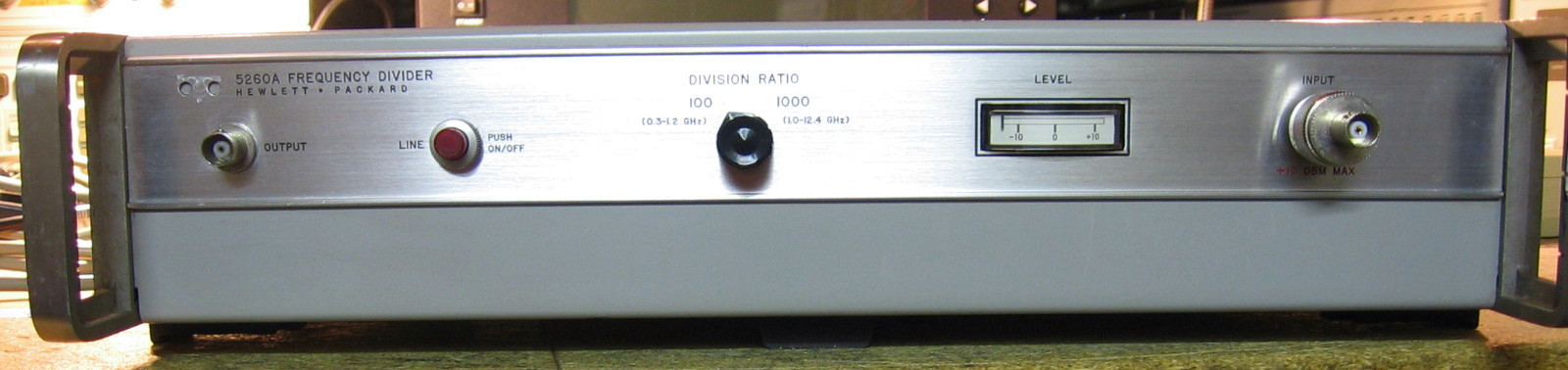
HP 5260A: 12.4 GHz pre-scaler. Suppose it's 1966 and you have a 12 GHz sine wave that you want to examine with your HP 5245A 50 MHz counter. What will you do? Well, one way is to heterodyne the signal down to a 50 MHz wide baseband, which is what HP did with 3 GHz signals in their 5254B plug-in. Another way is to build a 1000:1 pre-scaler. The 5260A will do either a 100:1 division for 0.3-1 GHz signals or a 1000:1 division for 1-12.4 GHz signals. The way they did this is simply ingenious and is explained in the April, 1967 issue of the HP Journal. Basically, the division is done digitally on a low (30 MHz) frequency and then two LOs and two microwave mixers do their magic at the GHz frequencies. The input amplitude requirements are a bit restrictive (-7 to +10 dBm) and there is but a single knob to select 1000:1 or 100:1. While I'm sure this thing was a technical marvel back in the 1960s (and cost $3,500), its usefulness was short-lived as pre-scaler ICs were employed shortly thereafter. ($CD) Grade: B+
Well, it ain't 1966 anymore, so I really don't have a need for something like this, especially since I have several microwave counters. But I couldn't resist it for $25. It was pretty much DOA and the first problem was that the 15V supply was being current limited down to about 4V. The offending part was a 10 uF electrolytic on one of the (many) circuit boards. After the P/S was fixed, it was still pretty much DOA. Marching through the diagnostic charts, I found a loose coupling wire on one of the oscillators. After fixing that, the thing sprang to life, but produced an output that was FM-ing greatly as if the oscillator was not harmonically locking to the input signal (which it wasn't). I resumed my march through the diagnostics, but about 15 minutes later, all of a sudden everything worked. I guess it simply took a little time for the 50 year old caps to reform. I must, however, voice my complaint about HP's calibration procedures in their manual. Usually the write-ups are very good and crystal clear (unlike Tektronix's cal procedures). But on the 5260A, the manual is filled with ambiguities and confusion to the point that I simply gave up midway.
Postscript: Went looking around for something to fix one weekend and found that the 5260A was completely hosed. What I thought would kill a Sunday morning turned into a one week marathon, however. The manual gives a long debug procedure, but I was getting nowhere fast with that - everything seemed to check out OK. I then went through the cal procedure only to find a pot that was supposed to adjust the VCO, but was doing nothing. I traced this to A6Q5, an ordinary 2N3906, that was defective. After replacing the transistor, things still were not right. Turns out that while I was marching through the cal procedure after the step involving the 2N3906, another transistor, A1Q2, that I already had checked out fine, went defective. After that one was replaced, things started to work. As I remarked in the original repair note, the cal procedure is one of the more difficult ones on an HP piece. But everything seems to be OK now.
Postscript^2: This is the piece that keeps on giving. Been about a year since the paragraph above and, sure enough, the 5260A has problems again. This time it was a couple more defective transistors. This 5260A surely has one of the highest defect rates I've experienced in an HP piece. It's a good thing that it is a pretty useless piece in this century at least.
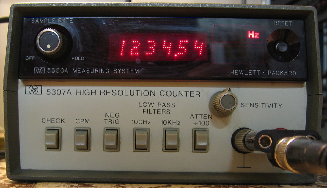
HP 5300A/5307A: The 5300A is a basic counter unit which accepts one of about a dozen different plug-ins. An HP 5307A "high resolution 1 MHz counter plug-in is shown mated to the 5300A. The HP 5300A was followed by the more capable HP 5300B (see next item). (PDF) Grade: C+
On this episode of Mythbusters, can you really fix a transformer by bashing it repeatedly with a hammer? Please, don't try anything you're about to read at home - I'm what you call an expert. When received, the 5300A had a blown fuse and promptly blew the replacement. The 5307A plug-in was not at fault since that worked with the similar HP 5300B unit. The problem with the 5300A was a shorted primary on the AC transformer. I bypassed the AC-DC conversion and powered up the unit from an external 22V power supply. This 22V then goes through the 5300A's switching DC-DC converter to supply the four required voltages. After a short time, my external P/S went into full current limiting with zero volts output. The problem was traced to the main switching transformer which had a short from primary to secondary (thus grounding my external supply). Oh, and it also blew up a Zener 68V protection diode across the switching transistor. At this point, I removed the custom toroidal potted transformer and lamented that there would be no way ever to get a replacement. While I had it on the ohmmeter, I noticed that if I squeezed the plastic cylindrical case, the resistance changed ever so slightly. OK, then I put it in a vise and squeezed even harder - more of a change. At that point, I tapped it with a hammer and noticed the ohmmeter move. I took it out of the vise, put it on the floor with the ohmmeter attached and beat the living hell out if with a hammer until little bits of Bakelite shell were chipping. When the ohmmeter read infinity, I stopped hitting it. Put the transformer in and the HP 5300A works fine. Of course, I still needed a replacement AC transformer. But for the $20 I would have spent on that, I made a $20 offer on another broken HP 5300A. When that was received, I simply pulled out the AC transformer, the main switching transformer and the Zener and put them in the first one (I don't really trust my hammered transformer very much). So the myth is confirmed - you can beat a transformer into submission.
On this episode of Mythbusters, can you really fix a transformer by bashing it repeatedly with a hammer? Please, don't try anything you're about to read at home - I'm what you call an expert. When received, the 5300A had a blown fuse and promptly blew the replacement. The 5307A plug-in was not at fault since that worked with the similar HP 5300B unit. The problem with the 5300A was a shorted primary on the AC transformer. I bypassed the AC-DC conversion and powered up the unit from an external 22V power supply. This 22V then goes through the 5300A's switching DC-DC converter to supply the four required voltages. After a short time, my external P/S went into full current limiting with zero volts output. The problem was traced to the main switching transformer which had a short from primary to secondary (thus grounding my external supply). Oh, and it also blew up a Zener 68V protection diode across the switching transistor. At this point, I removed the custom toroidal potted transformer and lamented that there would be no way ever to get a replacement. While I had it on the ohmmeter, I noticed that if I squeezed the plastic cylindrical case, the resistance changed ever so slightly. OK, then I put it in a vise and squeezed even harder - more of a change. At that point, I tapped it with a hammer and noticed the ohmmeter move. I took it out of the vise, put it on the floor with the ohmmeter attached and beat the living hell out if with a hammer until little bits of Bakelite shell were chipping. When the ohmmeter read infinity, I stopped hitting it. Put the transformer in and the HP 5300A works fine. Of course, I still needed a replacement AC transformer. But for the $20 I would have spent on that, I made a $20 offer on another broken HP 5300A. When that was received, I simply pulled out the AC transformer, the main switching transformer and the Zener and put them in the first one (I don't really trust my hammered transformer very much). So the myth is confirmed - you can beat a transformer into submission.

HP 5300B/5301A: The 5300B is a basic counter unit which accepts one of about a dozen different plug-ins. An HP 5301A 10 MHz counter plug-in is shown mated to the 5300B. The 5300B has all the basic counter and display circuitry and the plug-in serves as the signal conditioner. As shown, this combination works up to about 36 MHz. The whole thing is done in a few HP custom ICs, so they sold these units dirt cheap. They are very cute but certainly at the bottom of the HP food chain. (PDF) Grade: C
Postscript: Preemptively replaced the two 0.0022 uF Rifa Y-capacitors hanging off the power receptacle with 0.0015 uF non-Rifa Y-capacitors. I am somewhat surprised this 1979 built piece had Rifa capacitors - it is a tad early for them. The service manual (earlier edition) had them listed as 0.005 uF ceramic capacitors. And the HP 5300A (see previous entry) did not have any.
Postscript: Preemptively replaced the two 0.0022 uF Rifa Y-capacitors hanging off the power receptacle with 0.0015 uF non-Rifa Y-capacitors. I am somewhat surprised this 1979 built piece had Rifa capacitors - it is a tad early for them. The service manual (earlier edition) had them listed as 0.005 uF ceramic capacitors. And the HP 5300A (see previous entry) did not have any.
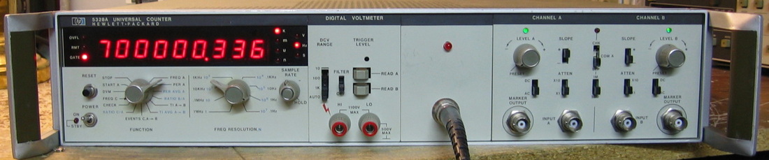
HP 5328A: This is a 100 MHz counter with Option 011 (HPIB), Option 021 (DCV) and Option 041 (HPIB controlled input section). HP built many pieces that were in production for many, many years and ended up being "classics" - this was one of them. It was at first a bit unsettling to use because it has separate controls for resolution and update time (sort of like decoupling RBW and VBW on a spectrum analyzer). But it grows on you. It is spec-ed for 25 mV sensitivity at 100 MHz, but I've done 139 MHz at <50 mV easily. I've got so many other counters (HP and non-HP) that I'm using the 5328A to count them. Postscript: Shortly after I got this, a buddy at work gave me a junker HP 5328A that had Option 030, 500 MHz prescaler (channel C). I removed it from his and installed it in mine. (PDF) Grade: B+
This piece was advertised on eBay as "doesn't power up, for parts or repair." The seller included some photos of the guts and I noticed they didn't look right. Indeed, the two main P/S filter caps were missing! When I received the piece, I saw that the previous owner had totally disconnected the P/S board which involved unhooking about 15 wires and removing 5 pass transistors. Saved me a lot of time! I pulled out the board and put in two replacement 4700 uF caps (and all the other electrolytics for good measure). There were also two 3W resistors that were discoloring the board, so I replaced those and elevated the new ones 1/4". Upon reassembly, everything worked fine except the DCV which was a bit unstable. To fix this just required a little tuner cleaner in one of the front panel switches. I also installed the channel C prescaler from a junker unit and drilled holes in the front panel for the input jack and overflow LED.
Postscript: As part of my "turn everything on once a year" policy, I fired up the 5328A only to find that the B channel was only working on the x10 attenuation setting, not the x1. It was a simple matter of finding the faulty reed relay which measured 1.1M when closed. Fortunately I had all the boards from the junker unit my pal gave me years ago, so out with the old and in with the older.
Postscript^2: Preemptively replaced the two 0.01 uF Rifa Y-capacitors hanging off the power receptacle with 0.01 uF non-Rifa Y-capacitors.
Postscript^3: One day I noticed that the Channel C, Option 030, 500 MHz prescaler wasn't working. The board consists of five custom HP ECL chips (amplifier, Schmitt trigger, multiplexer, divide by 2 and divide by 5) followed by an ECL-TTL translator and some TTL logic. Tracing through the signal path, it appears that the the input makes it through to the divide by 2 chip where it then disappears. The schematics and parts list do not match what is on my board, and there probably would be little chance of obtaining replacement parts anyway, so the best I can do is keep an eye out for a whole new Option 030 board.
Postscript^4: Found an Option 030 prescaler board for $35 shipped. It had a different part number (later date) than the one I had, but it seems to work fine. And it counts up to 900 MHz, way above the 512 MHz upper frequency limit specification.
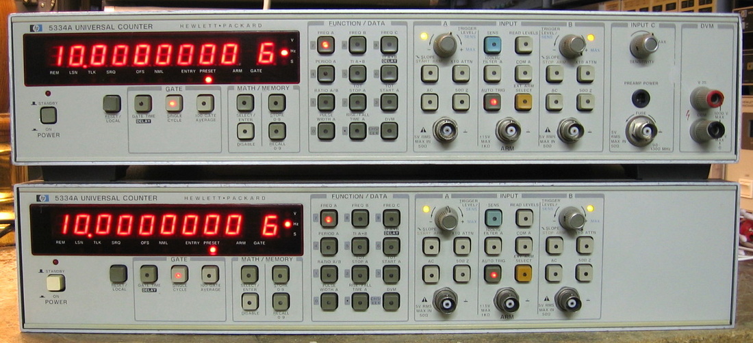
HP 5334A: 100 MHz universal counter with 1.3 GHz prescaler option and digital (DC) voltmeter option. Only sold by HP for a few years before they came out with the B model which was more inexpensive and had worse specs. I installed an EG&G OCXO (same as the HP 10811A) in it. The bottom unit (sans prescaler and DVM, but with original HP OCXO) was later donated by a retired colleague at work (thanks, Dan). ($CD) Grade: A-
Advertised by the eBay seller as "powers up, does not work." But the listing photo showed a row of dashes on the display. Not only is that the default behavior, but you can't even get to that display unless the unit passes the internal self-test. Oh well, his loss, my gain. Upon receipt, the only casualties were a blown input fuse on the C channel, a broken leaf spring on one of the pushbuttons and a smashed front panel. The latter two maladies were remedied while I wait to order the 50 cent fuse. As for the OCXO, a buddy had given me a small HP board marked 05334-6003 a few years ago. I threw it in a drawer back then. Turns out that this is the support board that is required to install the HP OCXO. Lucky me. And somewhat later, that same buddy gave me his HP 5334A!.
Postscript: One of the differences between the HP 5334A and 5334B models is that the A-version can store user settings. That means there is a RAM with a backup battery inside. Who knew? Anyway, one day upon power up, the 5334A threw error 5.2 which means it couldn't obtain the correct HPIB address. Normally, HPIB addresses are selected by a set of DIP switches on the back panel, but in the 5334A, they are stored in the RAM. That was the clue to go looking for a battery inside. Fortunately, the 3.6V rechargeable NiCd hadn't leaked too badly. It was replaced with my normal setup of two AA alkalines in a plastic holder with a Schottky diode in series to prevent recharging. The second 5334A I have fared somewhat better as its NiCd battery tested OK.
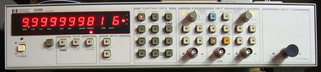
HP 5334B: 100 MHz universal counter with 1.3 GHz prescaler option. Designed to be inexpensive and used a lot of the newer ICs of the era to keep the parts count low. Amazing how HP can sell a counter for $10,000 (e.g. HP 5335A), then produce almost the same counter and sell it for $2,000. (PDF) Grade: A-
Postscript: As a colleague of mine, who purchased a 5334, pointed out, the standard (non-ovenized) crystal oscillator is extremely temperature dependent. HP's spec for the crystal is 5 ppm over a 50 deg C rise. That's a whopping 50 Hz at 10 MHz. I had to see it for myself, so I took the 5334B with the cover off and let it stabilize for an hour. I then simply walked about two feet in front of it and saw the display move about 0.1 Hz. Fanning it with a piece of cardboard moved the display over 1 Hz. While the 5 ppm spec might seem reasonable, even HP admits in one of their application notes that the drift isn't necessarily a simple linear curve - there can be very rapid rise and fall segments where a small temperature change can account for much of the 5 ppm drift. Bottom line: de-rate my A- grade by a full letter unless you get one of these with the OCXO.
Postscript: Preemptively replaced the four Rifa suppression capacitors with non-Rifa caps. Funny that the 5334A uses an integrated, sealed line filter, whereas the 5334B does it with discrete inductors and capacitors. Probably trying to save a few bucks.
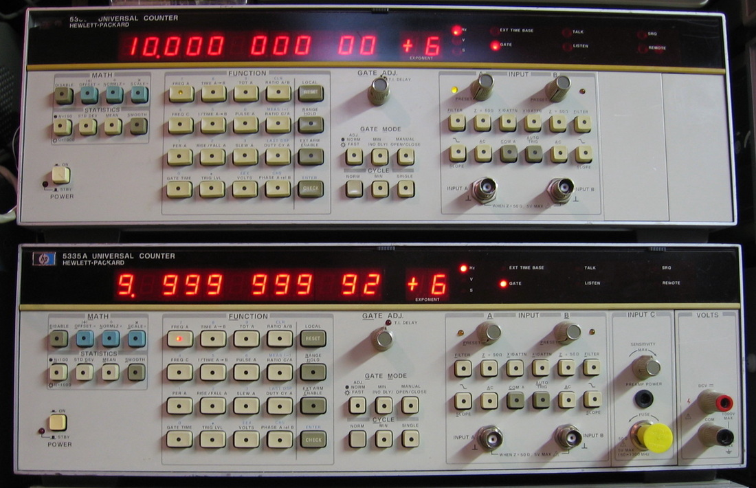
HP 5335A: The "standard" 200 MHz universal counter of the day. Lower unit has the 1 GHz prescaler and digital voltmeter options. Both units have HP OCXOs. These counters are very straightforward to use and are used often. (OM) Grade: A-
The lower unit had an open trimmer pot on the Channel C board. The upper unit rattled when I got it. Opened it up and found the main power relay bouncing around. The unit also had a shorted diode across A12K7. Also did the mod per the HP Service Sheet to rewire things around the main power supply relay.
Several years later, I was monitoring my repair of an HP 3325B on the counter and noticed the frequency seemed to be climbing steadily upwards. Luckily, I connected another very stable signal to the 5335A counter and saw the same thing, and when I opened up the counter, the 10811A OCXO was cold to the touch. Normally, the OCXOs fail with an open thermal fuse, but after taking the cover off and checking, the fuse was intact. Turns out that the OCXO has a current limiting circuit (about 0.4 amps) when it starts up. This circuit uses a voltage divider from the Vcc to get 0.2 volts on one side of an op-amp and the heater transistor current across 0.5 ohms to get the other input to the op-amp. By shunting away base current from the heater transistors, the op-amp limits the current to 0.2 V /0.5 ohms = 0.4 A. Turns out that a simple 19K resistor in the Vcc voltage divider opened up which put the + terminal of the op-amp at 0V. The op-amp did its thing and made sure that there was 0V at the - terminal, i.e., turn off the heater transistors. Word to the wise: it is extremely difficult to work on the OCXO. Not only are things wedged inside, but the circuit board cannot take any heat from solder/desolder without some sort of damage.
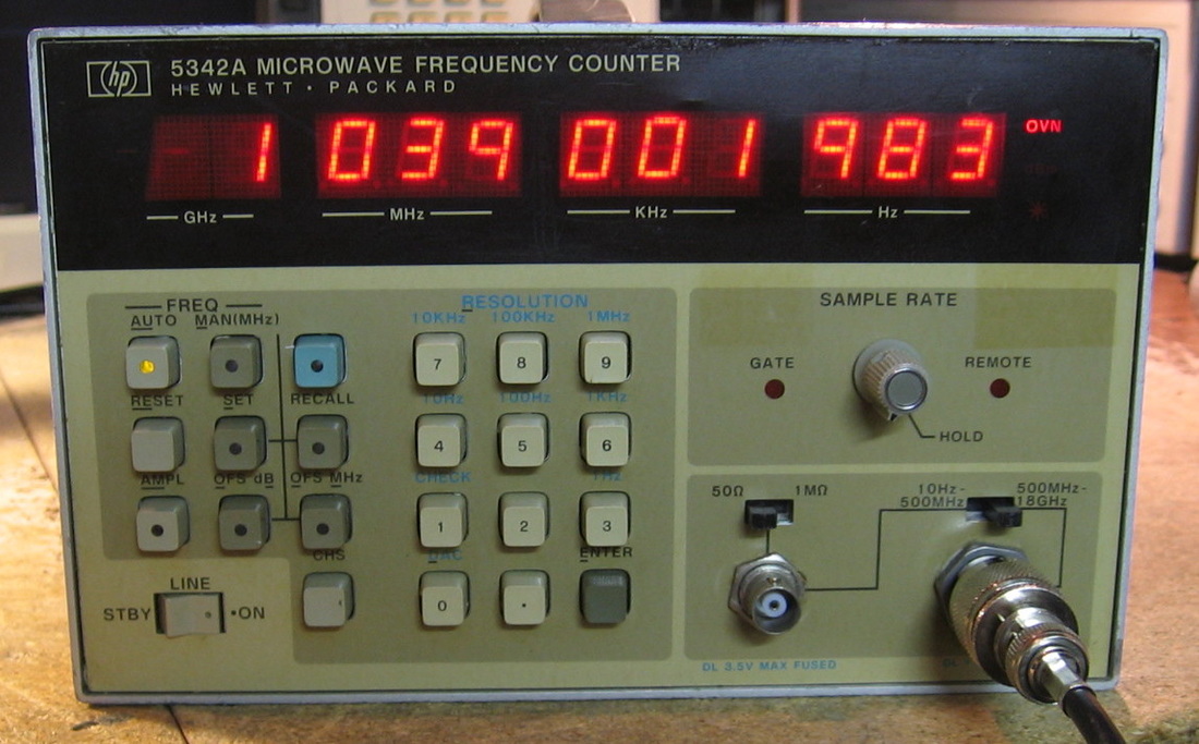
HP 5342A: Microwave counter to 18 GHz. Similar performance to my EIP 351D. However, the heterodyning down to the direct count baseband is done quite differently. The EIP counter runs a 200 MHz signal with lots of harmonics through a YIG filter that is swept up to 18 GHz. When there is a detected IF signal, the YIG stops and the counter is able to tell which harmonic was close to the input. With the HP 5342A, the fundamental oscillator frequency is swept. Eventually, some harmonic will be close to the input, but you can't tell which one yet. By using a second frequency, one can compute which harmonic was the offender and the input frequency can be calculated. I like the EIP method as it is more to the point. On the other hand, when the EIP YIG filter hits 18 GHz, it stops. With the 5342A, sufficiently many harmonics are generated that it will count to 26.6 GHz (with reduced sensitivity of course). My unit has both Option 001 (OCXO) and Option 002 (amplitude display). (PDF) Grade: A-
The seller did not indicate the status of the unit, but the picture showed random characters on the display. When I received the unit, the initial power-up also displayed the same thing, but about 5 seconds later, it went through its self-test, with all digits displaying "8", and then seemed to work fine. I haven't had any problems since. But, you know me, I went looking for trouble. I figured maybe something was wrong with the P/S. All voltages checked fine, but when I pulled the regulator board, an area around a TO-220 transistor was burnt to a crisp and one of the traces nearby had been obliterated. The previous repairman jumped around the broken trace, but left the transistor in place. The transistor was actually cracked in half! I pulled the transistor (MPS A51) and it was open, so I replaced it with something suitable. I also pulled a 2N3906 that was connected to it and that was partially shorted. The 2N3906 was replaced, the trace fixed, and all seems well for the moment.
Postscript: I didn't at first appreciate Option 002 (amplitude measurement). In fact one of the reasons I obtained the Tektronix 2754P spectrum analyzer was that I really had no capability to measure power higher than about 1.5 GHz. But the 5342A is sufficient and measures from about -30 dBm to +20 dBm across the entire range. At least at 1 GHz, the readings match my signal generator to within 1 dB everywhere. Now, getting back to repairs, the unit very occasionally would either not start or would lock-up. I finally caught it in a non-start condition and determined that the uP had no clock. I thought I had traced it to a bad DIP switch on the uP board that passes the clock signal and thus hard-wired the switch closed, as it is only ever opened in some strange debug mode. But then it happened again. When I gave the unit a strong rap on the cabinet, it recovered. So it sounds like a mechanical problem, and the only other mechanical thing touching the clock circuitry (which is derived from the 10 MHz OCXO) is the back-panel int-ext oscillator switch. The switch looked OK on the ohmmeter, but I squirted cleaner it in just to be sure. The counter has been running several hours without incident now, so stay tuned...
Postscript^2: Well, that didn't last long - the unit still either doesn't boot up or locks up shortly thereafter. It had nothing do with the uP clock signal, but rather the 5V analog supply (the uP clock signal is and-ed with a signal from the internal/external oscillator rear panel switch and that signal is dependent upon the 5V analog supply). The 5342A's switching supply develops 6V and that is fed through a standard 5V linear regulator consisting of an NPN pass transistor driven by an op-amp through an NPN emitter follower. What seems to be happening is that the 6V drops down below 5V which cuts off the pass transistor (insufficient C-E voltage). But the emitter follower feeding the base of the pass transistor has its collector attached to 15V, so the emitter follower drives all the necessary current through the emitter-base junction of the pass transistor. And since the emitter follower is not sufficiently rated, it burns to a crisp. At one point, I disconnected the emitter follower's collector and let the pass transistor simply be driven from the op-amp, through the E-B of the follower. That seemed to prevent the follower from frying, but occasionally I still would not get 6V out of the switching supply preceding all of this, and so the pass transistor wouldn't energize and the unit would lock up. I believe I now have found the culprit - a simple cold solder joint on the bridge rectifier of the secondary of the switching supply. Now, instead of getting about 5.8V out of it, with the thing dropping down to about 3V when the unit locked up, I'm getting a steady 6.2V. Everybody now seems happy.
Postscript^3: The A21 power supply board was a real mess after I got done with all of the debug and repair. Many traces and pads had been lifted and I had to solder in a lot of jumpers. Along came an eBay listing for a working A21 board for $20, so I grabbed it. While the 5342A worked fine with the replacement board, I noticed that upon startup, the -5.2V line started out at about -4.7V and it took several minutes to get to its final value. Turned out that the MPS A51 transistor had a nice bulge and crack in it and was the culprit, just like in my original repair. Go figure.
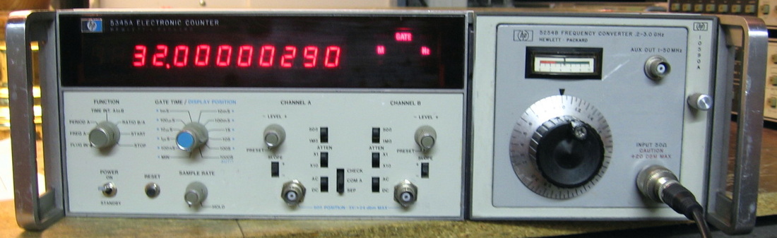
HP 5345A: The HP 5345A is a 500 MHz counter and one of the first models to measure frequency by first calculating period (time interval). It multiplies the basic 10 MHz OCXO up to 500 MHz and then randomizes the clock to avoid the usual +/-1 count errors from input signals harmonically related to the unjittered clock. The 5345 is basically a single channel frequency counter, but also has a B channel for A-to-B time interval and A/B frequency ratio measurements. It will also accept a variety of 5300-series plug-ins and, with the proper adapter, will also accept 5200-series plug-ins. The unit shown has an HP 5254B 3 GHz heterodyner plug-in with the HP 10590A adapter unit. The photo shows a 1032 MHz input where one reads the "10" off of the plug-in dial and the rest off the 5345A display. So the measured frequency is 1032.0000029 Hz which translates into a 2.9 ppb error between the counter's time base and the signal generator's time base. The extra digits provided by the heterodyner produce effectively a 13 digit count at the maximum gate time! (PDF) Grade: A-
Maybe I should call this an HP 5345F instead of HP 5345A, the F standing for flunk, for I was unable to completely fix this unit. Upon receipt, the fan was all gunked up and wouldn't start turning. That just required a careful dissection and lube job. Electrically, however, it was very flaky. I spent about 4 hours building two extender cables just to be able to get to the adjustments behind the front panel. I managed to slip a screwdriver which shorted something on the B channel. However, shortly after that, the A channel stopped working. Nothing I did to the B channel should have had an impact on the A channel, so it remains a mystery. The bottom line is that I swapped one of the HP hybrid chips between the two channels and at least now I have a perfectly working counter on the A channel. So that gives me frequency and period, but no time-interval or ratio. Oh well, nothing more I can do about it.
Postscript: Well, the B channel isn't completely dead, just degraded. The A-to-B time interval and the A/B ratio functions do work providing the input is greater than 100 mVrms, the input impedance is set to 1M and the frequency isn't ridiculously high (I was using about 20 MHz). No adjustments make it any better. And this is with the LM310 I shorted removed from the circuit and the B channel permanently put in preset mode.
Postscript^2: In what has to prove the existence of God, I actually found an eBay seller who had the HP hybrid IC I needed for a mere $5.00. Tack on another few bucks for an LM310 and the HP 5345A now works as it should.
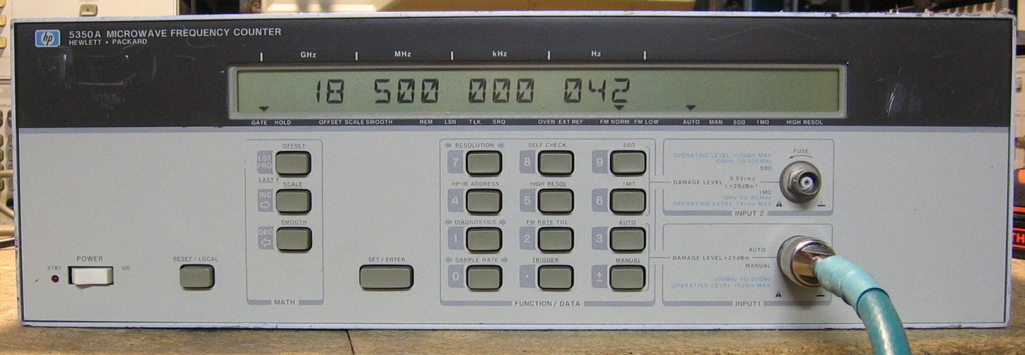
HP 5350A: Microwave counter in two bands: 10 Hz - 525 MHz and 500 MHz - 20 GHz. HP also made a 5351A and 5352A good to 26.5 GHz and 40 GHz respectively. I have a sneaking suspicion that one can change some jumpers on the motherboard and turn my 5350A into either a 5351 or 5352. However, the actual models have different connectors than the precision N-connector on my unit, so there certainly would be some losses unless I changed the connector. The 5350A is pretty much a vanilla unit that simply shows the frequency to 1 Hz resolution (higher resolutions are possible in the lower frequency range). There isn't much control or functionality beyond that. And HP got the cost down by using several custom hybrid components. Shown in the picture measuring my HP 8672A microwave generator set to 18.5 GHz, -10 dBm. All in all, a basic unit that, in my opinion, is not really any better than my earlier HP 5342A counter (see entry above). HP did make a follow-on 5350B that offers a bit more sensitivity and runs a bit faster. ($CD) Grade: B+
I took a chance on this one for $75. The seller had offered it for $200, then marked it down to $100, then took my $75 offer. It was listed as having Option 010, the ultra high stability OCXO. This OCXO, HP 10811-60211 is, I think, a hand selected standard 10811-60111 with better specs. So I figured if the front-end microwave converter was toast, which is about the only unfixable thing in the unit, at least I would have the better OCXO. But alas, the seller misinterpreted a smudge on the back panel next to the words "Option 010" as meaning the option was included. It wasn't, nor did it even have the standard OCXO - just a simple TXCO. I had the normal OCXO sitting around in one of my spare HP 5335A counters, so I stuck it in the 5350A. And, of course, the 5350A worked fine so I am a happy camper. The anemic yellow LED backlight needs changing and I will probably put in white LEDs when I get around to it.
Postscript: I got around to replacing the weak yellow LEDs with white ones. Makes it a bit easier to read the display in low ambient lighting. Unfortunately there doesn't seem to be a light spreader in this particular display, hence the light is a bit uneven.

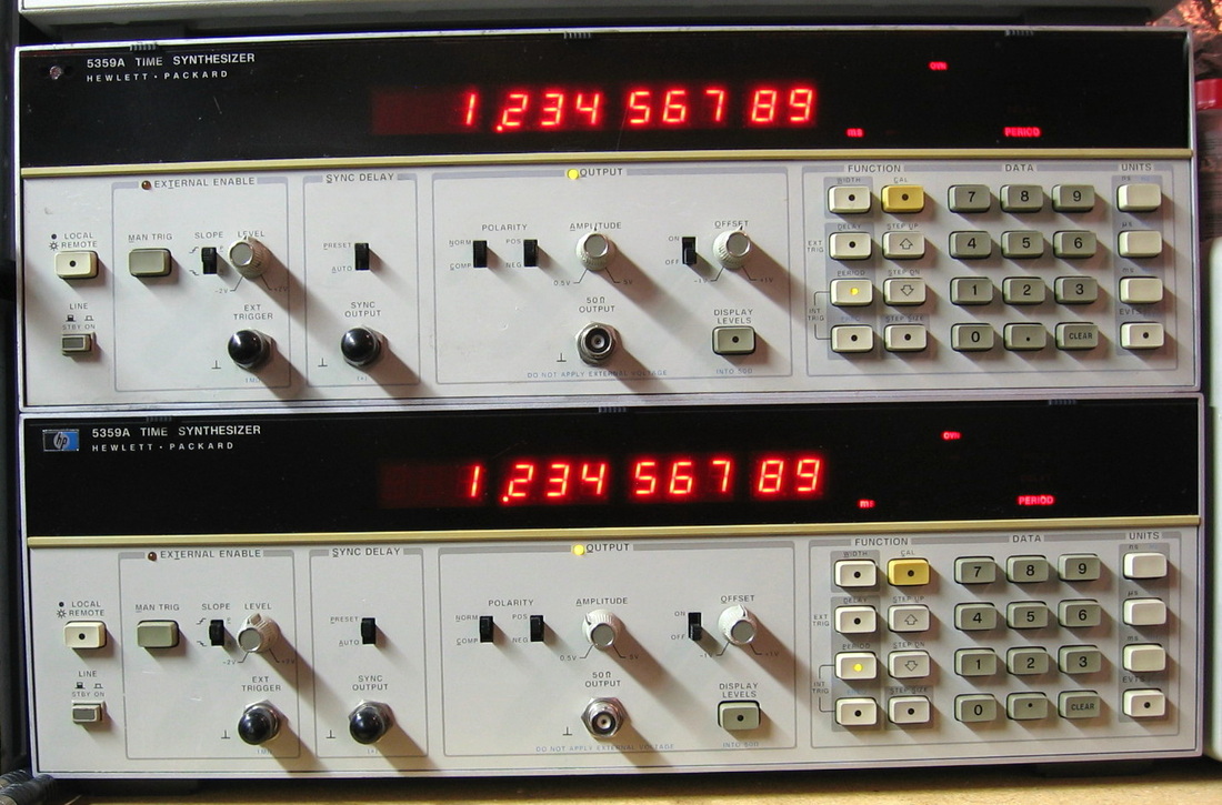
HP 5359A: Very, very expensive dual of the HP 5370 counter. Instead of counting, this puts out pulses at prescribed times/widths. The upper unit had a broken custom output amplifier IC and was replaced by a board designed by me. If you are looking for the ultimate time mark generator, this is it. If you just want to impress your friends by putting out a pulse exactly 13.456873 usec after a trigger, this is it. If you want to draw over 200 watts (a lot for an HP piece), this is it. Important note: The 5359A is a time synthesizer, not a pulse generator. Sure, you can set it to output a pulse train, but only the width of the pulses are what it cares about. The actual period of the pulse train can and does wander. So if you reach for this piece without thinking and hook it up to a frequency counter, the jittery readings might lead you to conclude the 5359A is faulty - it isn't. (PDF) Grade: A
One of the units worked fine. The other one produced funky output. The output amplifier is a custom HP hybrid which can't be replaced. So I built a board using an analog multiplier and some ECL glue chips to replace the hybrid. It doesn't give me quite as sharp rise/fall times as the other working unit, but it's good enough.
Postscript: For checking/calibrating pieces like a time interval analyzer (5370A, 5371A, 53310A), one can set the 5359A, for instance, to a 100 nsec pulse width and then measure pulse width on the analyzer. However, the 5359A with the replacement amplifier has particularly long rise times that can influence the measurement. Fortunately, there's a better way. Simply use the 5359A's two auxiliary output jacks on the back panel that put out nice sharp pulses synchronized to the start and stop of the output pulse (these are ahead of the output amplifier). Then put the analyzer in time interval mode, not pulse width. Works like a champ.
Postscript^2: A few years later, I traded a work buddy some spare Fluke 8502A boards for the 5359's A18 output board from his spare unit. I ripped out my hybrid replacement board and installed the new HP board with the functioning output amplifier. But even then, the unit threw error 9.1 and the output was all wrong. Turned out to be a faulty 2N3906 (A17Q4) on the next board over.

HP 5360A/5365A: HP called this a "computing counter." What does that mean, you may ask? Well, I'll tell you. Designed as a reciprocal interpolation counter (i.e., measures period), HP needed to do some arithmetic to display frequency. The way they did this in 1970 was to build an actual computer out of 7400 TTL logic. Now this isn't your standard microprocessor type of computer, no, this is a hardwired "programmable" computer. Hardwired-programmable sounds like an oxymoron, however there is a method to HP's madness. The mainframe has several hardwired "routines," and there is another logic board containing a program in the HP 5365A input module and another in the time-interval plug-in (which I don't have). Moreover, HP sold a keyboard that went with the 5360A allowing it to function as an actual computer (adds, multiplies, register writes, reads, etc.). If that wasn't confusing enough, HP also sold an external programming interface box which could be programmed by inserting various cards with matrices of diodes setting what was equivalent to machine code. But, back to the counter. It nominally is a 10 MHz counter, but the B-channel of the 5365A input module has a 32:1 prescaler, so the thing is good to 320 MHz (I've pushed it past 400 MHz reliably). One can select the number of digits to display and the gate time. HP claimed that this was the most accurate counter in the world when it came out. And the reason was their interpolation scheme. The thing only has a 10 MHz clock, but they charge up a capacitor from the gate starting (or ending) point to the nearest clock pulse and then discharge the current through a capacitor that is 1000 times smaller. This allows the 10 MHz clock to effectively count at 10 GHz. Simply brilliant. Yet it appears that HP abandoned this approach in many of their subsequent counters. As far as complexity goes, this piece takes the cake. Over 400 TTL chips spread out over 30+ boards. Two separate ovens and a wire-wrapped backplane with probably 1000 connections. HP claimed that it took 6-1/2 man years of effort to do the mechanical design. I'll give this a high grade only because it must have been a technical marvel at the time. And for $7,000 in 1970, it had better be. ($CD) Grade: A-
Postscript: After I had fixed this (and the spare unit described in the next listing), I came across a seller offering the HP 10539A adapter. This piece plugs into the right hand compartment and allows the plug-ins for the HP 5245 series counters to be used with the 5360A. I've updated the photo to include the adapter running the HP 5253B heterodyner plug-in.
I spent a whopping $20 + shipping for this piece, which was advertised as non-working. After I bought it, the seller e-mailed me and said he had another (broken) unit that I could have for an additional $20. I declined because I thought one of these was enough. But after I received the counter and took one look at the guts and at the manual, I realized I was in a world of hurt. The service manual did have some rudimentary troubleshooting information, but most of it required the keyboard and a special support board. I might have had a chance if I could narrow the problem down to one or two boards. But alas, the logic was so spread out and intertwined across boards, it was futile. Basically the counter was just sitting there with all zeros displayed. The arm-count-compute-display lights were supposed to be toggling, but they were simply dark. None of the arming or gate signals appeared at the back panel jacks.
So I quickly wrote back to the seller and got the second unit. The seller indicated that the display didn't work on that unit. But that was OK if the rest of the counter was working because I just wanted to swap boards into my first unit. When the second unit arrived, the display was dark and so was most everything else. That's because the 5V supply read 0V. I quickly traced that to a bad electrolytic in the regulator circuit and fired the counter up. Thankfully the arm-count-compute-display lights were toggling along. So it appeared that the counter was working and it didn't take long to find and replace the three faulty boards in my first unit.
Theoretically, now that I have a complete working unit, I could go back to the second counter and start fixing that by the comparison method. However, without the proper schematics for the display, that appears unlikely. For HP originally designed the 5360A with individual Nixie tubes. Sometime after a few years, they moved to a Burroughs Panaplex gas discharge display. This required three completely different boards that are not shown in my service manual.
Postscript: Turned on the (good) unit after about a year and it was all screwed up. The count digits were correct, but the exponent was all wrong. For instance, 10 MHz read 100.0 mHz. This changed as a function of the gate time. The problem was traced (with the help of the boards from the spare unit) to A23, U10 (7400) with one bad gate. It took me about 1-1/2 hours to find the culprit - not bad for a device with 400 ICs.
.
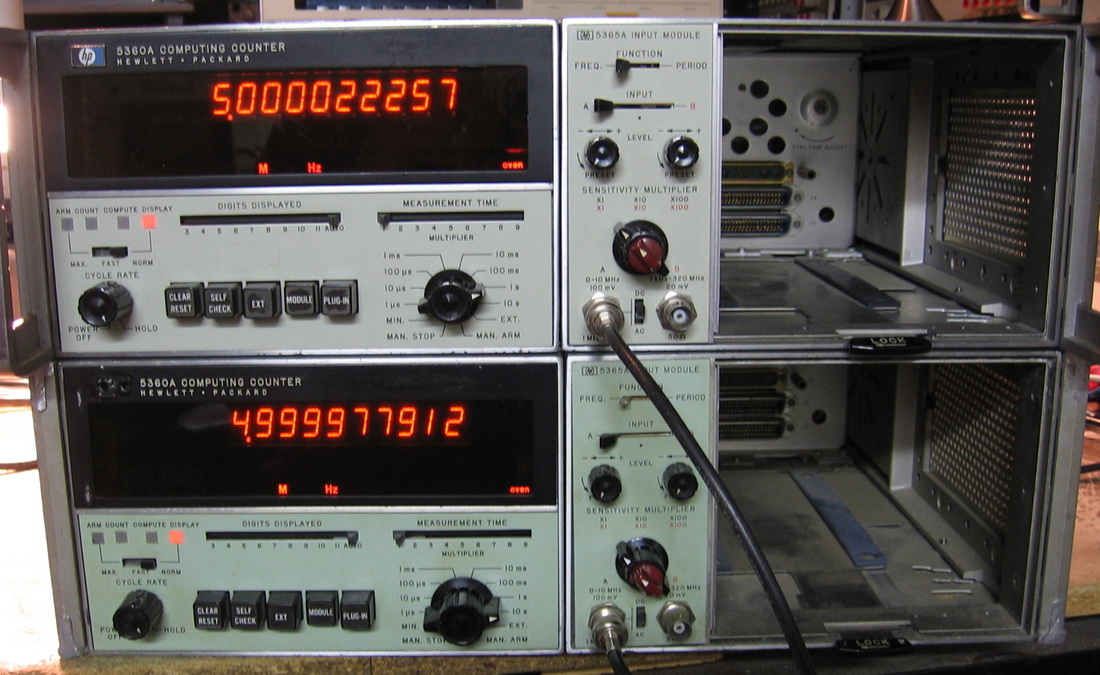
HP 5360A/5365A Spare: The spare HP 5360A (bottom) used to fix the first unit (top). Now, both are running just fine. The photo shows the 5 MHz internal oscillator from the top unit being counted by the bottom unit, and vice versa. The two ovens haven't fully warmed up (and the oscillators haven't been calibrated yet) - hence the small discrepancy in the counts. ($CD) Grade: A-
Recall from the description of the HP 5360A (listed above), this second unit was received non-operational and three boards were pulled to fix the first unit. The initial fix to this unit was a shorted A2C3 which brought down the power supplies. With three faulty boards exchanged from the first unit, and most probably other bad boards, the crucial item on the agenda was to fix the display, which was dark. If the display couldn't be fixed, I didn't see the point in going any further with the repairs. Luckily, Artekmedia responded to my inquiry and was able to provide an updated manual which had the proper display schematics.
The display consists of a main board which receives, stores and forwards the digit information from the arithmetic counting circuitry. Plugged into this main board is a second board that drives the digit selection (a multiplexed display) and plugged into the second board is a third board that basically drives the 9-segments of each digit. This board also drives 17 neon light indicators below the display. The actual display is a Burroughs 13-digit Panaplex neon panel which plugs into the third board. Using the various display boards from the first unit, I determined a major fault with the first main display board. The problem was traced to a faulty A54U10 74161 counter which was supposed to strobe the digit information out of the RAM on the board. No strobing meant that the display thought it was "done" and remained dark. A check of the second board showed two things. First was a shorted driver transistor and the second was a severing of three traces on the board from someone who used too long a screw in the top cover! The traces were fixed and all 13 MPSA42 driver transistors were replaced. The third display board had many bad neon bulbs and about 1/4 of the MPSA42/92 transistors tested bad. All 37 transistors and 17 neon bulbs were replaced. I also took the opportunity to replace the 62K 1/4-watt neon dropping resistors with 1/2 watt versions since the bulbs draw 2 mA and thus the dissipation was close to the rated 1/4 watt. Finally, the actual Panaplex display did not light up the "d" segment on any digit with 180V supplied to the proper pins from my Fluke 334A calibrator. I carefully dissected the display and found a disconnected bonding wire.
With the display now functional, I could see a lot of stuff very wrong with the counter: 1) the 10 MHz self test would sometimes read 1 MHz or 100 MHz, 2) the neon units indicators (m, k, M ...) were incorrect, 3) the count and compute neons didn't flash as expected, 4) the number of displayed digits could not be correctly set, 5) the calibration readout (1000xx1000) was completely screwed up, and so on. Not surprising because I knew at least three boards were bad. It took several weeks of painstaking schematic tracing to find all of the bad chips (remember that the HP 5360A has about 500 TTL ICs in it). The short list of defects was A6U9 7402, A19U17 7476, A21U12 7402, A21U21 7400, A23U2 7473 and A32U12 7473. I had no hope of finding or building an extender board, so I basically took a board out of the unit, put it on the bench and hooked up 5V to the board. That left about 25-50 inputs (via the edge connector) on each board floating, which generally gets interpreted as a TTL high. Then I used a logic probe and the schematics to check outputs of gates. Luckily, most bad chips were spotted this way. Because of the complexity and convoluted design of the 5360A, even the simplest fault can only generally throttle the possibilities down to about 3 or 4 boards.
All in all, probably one of the most difficult fixes I've ever done. I have to believe HP must have had a steady stream of exchange boards to its customers during the support lifetime of the 5360A. I bet they couldn't wait to end production.
Postscript: The fixes of both the HP 5360A counters did not include any potential problems with the plug-in module compartment because I didn't have any plug-ins. However, I purchased the HP 10539A adapter unit and that exercises additional functionality in the 5360A. I am happy to report that both counters work fine with plug-ins.
Postscript^2: Turned this on after a year or so and the display was all screwed up. Needed a slight "persuasion" to reseat a few boards. I've said it before and I'll say it again - the HP 5360A is and was an absolute maintenance nightmare.
Postscript^3: Another few years and time to fire this piece up again. This time, the display was flickering, the count's decimal point was screwed up, the units prefix was wrong, etc. I thought I had fixed all this stuff long ago. Using the other unit, I determined that the main display board, A54, was the culprit. Many fruitless days of debug later, I found a minute solder bridge across two traces. It could only be seen with a strong magnifying glass. Removed the short and all is good. Well, not quite - the number of digits displayed selection does not work. This was traced to my original fixes, years ago, when I put in a 74LS54 as a replacement for an SN7454. Not so fast, the pinouts are slightly different. A new SN7454 fixed all.
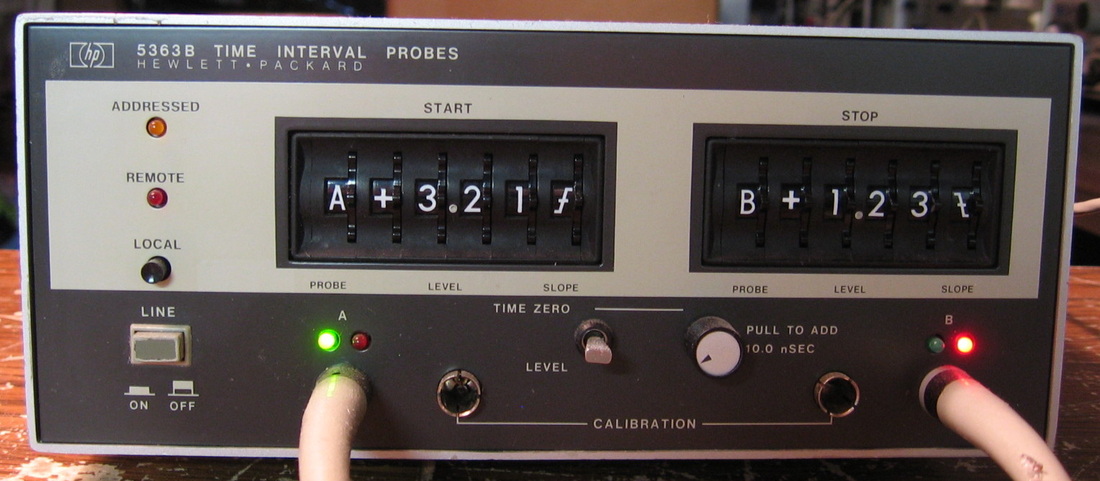
HP 5363B: The accuracy of time interval measurements on a counter is somewhat determined by how accurate the counter's trigger levels can be set. The 5363B has two probes and circuitry to very precisely set the trigger levels to user selectable values. It can also zero out any probe time delays. One feeds the probe outputs of the 5363B to a time interval counter like the HP 5370A. The 5370A is pretty accurate by itself, so I don't often use the 5363B. (PDF) Grade: B
Discovered a flaw in the thumbwheel switches many months after I first acquired this. Simple open diode.
Discovered a flaw in the thumbwheel switches many months after I first acquired this. Simple open diode.

HP 5370A: While designed primarily as a time interval counter (the dual to the HP 5359A time synthesizer), the HP 5370A is a high precision 200 MHz counter. Uses a very unique interpolation scheme based upon relatively prime clock intervals. The internal clock is scaled up to 200 MHz from an ovenized 10 MHz oscillator. Matches or exceeds present day counter specs. HP made a "B" model that is slightly better and a lot more expensive on eBay. But this will do just fine. They really don't make them like they used to. (PDF) Grade: A-
Replaced two front panel switches, added 35 pF from A18TP2 to ground to clean up noise in the B-channel trigger voltage display. Installed HP 10811A OCXO.
Postscript: One day, after about an hour run time, the display went dead. One of the internal fuses in the P/S had blown. So I put in another and the unit fired right up. Came back about an hour later and the new fuse had popped. Really, the only way the fuse could blow is if there is an overvoltage condition that fires a zener and shorts out the circuit. But the zener tested fine. However, if there was something funky with the pass transistor, I suppose it might pass enough voltage to cause an overvolltage condition. So I pulled the 2N6050 PNP Darlington and put in on the Peak DCA55 component analyzer. It read it as two diodes, clearly wrong. I guess that until it heated up, it somehow regulated a little bit, then poof. Anyway, a new 2N6050 was procured.
Postscript^2: One day, the unit powered up and immediately locked up. A check of the power supply showed the -15V supply had folded back to about -0.3V, and an ohmmeter revealed a short on the -15V rail. I've done the "standard" procedure a million times - leave the ohmmeter hooked up and start pulling boards until the short goes away. Then look for the shorted capacitor on the offending board. In this case it was a 10 uF tantalum, C35, on A21. In fact, a close inspection of the cap showed a little dimple in it (where it must have blown)
Postscript^3: One day years later, the unit powered up and immediately locked up just like described in Postscript^2 above. Same deal with the -15V supply. This time it was the other 10 uF tantalum, C17, on A21. About five minutes after I fixed that, the display went dark and the +15V supply folded back. The problem now was on the A6 power supply board with another shorted tantalum, C2.
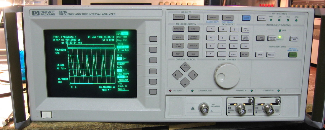
HP 5371A: Call it a "Frequency and Time Interval Analyzer" or call it by HP's later nomenclature, a "Modulation Domain Analyzer". This piece, along with the HP 5372A and HP 5373A, were precursors to the HP 53310A. You can read my description below of the latter to understand exactly what the 5371A does. The 5371A is the basic model and the 72 and 73 added some hardware acceleration and other less important features. The 537x uses HP 5400X input pods found in many HP scopes (standard is the 50 ohm 54002, but I have a bunch of 1 Meg 54003's in my HP 54300A multiplexer that I also could use). It is interesting to note the advancements made in the approximately 5 years between the 537X series and the 53310A. The 537X series uses primarily standard DIP ICs, a 68K uP and a massive linear power supply, whereas the 53310A uses virtually all surface mount ICs with some ASICs mixed in and a switching supply. However, the 537X base model goes to 500 MHz, while the 53310A only goes to 200 MHz. The 537X also has a 10811 OCXO as standard. And the 537X has a few more measurements (e.g., Allan variance) and the ability to display the data in both tabular form and histogram. Perhaps the nicest feature of the 537X is the ability to measure (and display statistics) for two independent channels at the same time. The biggest difference between the 537X and 53310A is the computation speed. I clocked the 53310A as being 33x faster doing a repetitive histogram of a collection of frequency measurements. My conclusion is that if you are really trying to delve into a single measurement, the 537X is the superior machine. But if you like to adjust equipment or fiddle around while watching the display, the faster computation rate of the 53310A is the ticket. And for the lack of speed, I'm deducting a few points from a solid grade of A. (PDF) Grade: A-
I rescued this one by the skin of my teeth! A buddy at work found an eBay seller offering two of these for $300 shipped. One was advertised as working, but had broken glass on the CRT cover plate (and also a non-functioning front panel rotary encoder as it turns out). The other one was advertised as powers on, but no display. Well, it took a little bit of persuasion, but I finally plunked down $150 for the non-functioning display unit and my pal took the other one. I received the unit exactly as described and began the debug. The display and display control board were 3rd party (as is usually the case in a late 1980's, early 1990's HP piece), so of course there were no schematics. When I went to discharge the CRT, there was no loud pop and I convinced myself that the anode wasn't getting the 10 kV it deserved. This usually points to a bad flyback transformer (unobtainable), but I plodded on. At this point, I borrowed an old CRT monitor with H-sync, V-sync and video BNC inputs, and connected it to the 5371A. Fired it up, saw a nice display, ran all the self-tests and everything passed. So at least it was worth continuing the fix. I pulled the CRT board and found a resistor burnt to a crisp. My pal read me the color code from his unit, a 150 ohm 1/4 watt resistor. I tacked one in, hit the power switch and let out the smoke. A quick check with the voltmeter showed about 330 VDC across this 150 ohm resistor. My ohmmeter showed about 120 ohms to ground on the far side of the resistor (the 300V side is correct as it comes off the flyback as part of the focus circuitry). I pulled and checked all the resistors and caps, but found nothing out of the ordinary. Then I held the board up to a strong light and saw the problem. There were carbon blotches deep beneath the surface of the board making contact with lots of pairs of adjacent traces. What was amazing was there was no indication of any of this looking at the surface. I got out the awl and dug the carbon out, fired up the 5371A and ... victory!
The story could stop here with the proverbial happy ending, but nooooo. After I fixed the CRT board problem, I put back all the various board cover plates, panels, etc., that I had removed. Turned on the machine and it hung. Restarted it and it began to fail three tests on the A6 board. Finally, it went dark and all five P/S voltages folded back to zero. A quick check showed zero ohms between the -15V test point and ground. When I removed all the mechanical parts, I saw the problem. A long metallic RF gasket had fallen off one of the board cover plates and lodged itself right up against a 140-pin edge connector of the A6 board. After the initial horror had worn off, I pondered the possibility that I had fried somewhere up to 60 ICs on A6. Now, I could bore you with the methodology I used, but I won't - I'll just give you the answer. A single transistor in a CA3127E 5-transistor array shorted it's collector protection diode down to the chip substrate which was being supplied -5V. This forced the collector to -5V which then pulled one of the inputs to a PAL16L8 to -5V. This redefined the notion of ground for the PAL, rendering a TTL high near zero volts. The outputs of the PAL were tied to bits 0-6 of the internal 16-bit data bus that runs data all around A6, pulling down the seven bus lines and completely hosing the board and causing all three A6 self-tests to fail. Bottom line: a new CA3127E fixed all problems. Now, there was some amount of debug skill on my part (especially since I didn't have an extender board for A6), but I got REAL lucky on this one!
Postscript: I don't know when to leave a good thing alone, so I decided to risk further damage and clean up some odds and ends. First, I installed a new 3.6V lithium memory backup battery on the uP board. But the biggest problem was the dirt behind the glass cover plate in front of the CRT which made the display a bit smudgy. I pulled the front panel, which was a job and a half, and removed the attached CRT. There was a thick film on the glass cover as well as the face of the CRT. It was caused by a sponge-rubber gasket surrounding the CRT that had decomposed nearly into dust. So I manufactured a new one out of some foam packing material, cleaned it all up and put it back together. As I was assembling the various metal covers, and manipulating the unit into various positions, I heard a "rattle, rattle, clunk" when I turned the unit over. Having learned my lesson already, I dissected the unit until I found the culprit - the captive screw that holds the top cover on. However, my top cover already had a replacement screw in it. So my conclusion is that the captive screw got lost in the unit many years ago and the previous owner had simply put another screw in the top cover. All these years, the screw had been lodged inside somewhere - a disaster waiting to happen!
Postscript^2: After six years, the 3.6V Lithium backup battery died (the service manual claims a three year life) and was replaced.

HP Counter Summary: In the Beginning, God created the HP 5245 counter. And it was good. But not too good, as God was really no big fan of Nixie tubes. And it wasn't cheap, and since The Chosen People were always on the lookout for a bargain, especially if they had relatives in wholesale, He created the 5300 series. But alas, the story goes that Moses came down from the mountain with the 10 commandments just in time to quell a riot from the impatient masses. That's what they would like you to believe. The real story is that the masses were rioting against the 5300 series counters. So God created the 5328A which begat the 5334A which begat the 5334B which begat the 5335A which begat the 5345A which begat the 5370A. And after the 5370 series, God rested. He finally got it right. [The astute reader will note that I took some liberties by ordering the set via the model number; that isn't the order that HP actually released them. So sue me.]
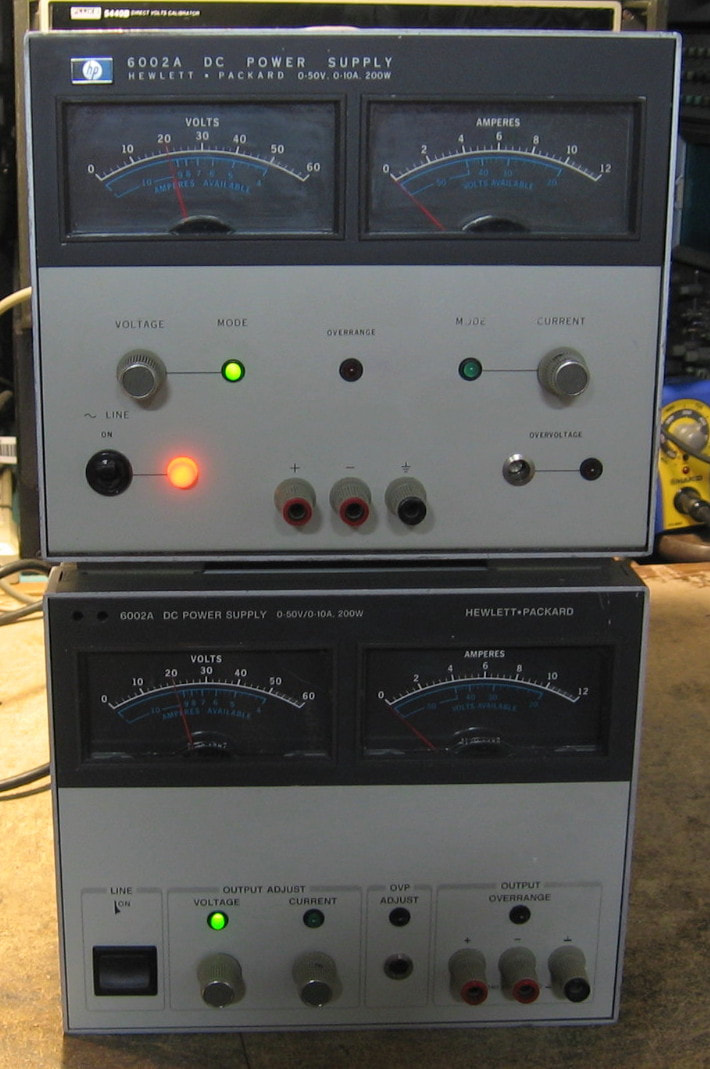
HP 6002A: This is a 200 watt linear power supply capable of a maximum voltage of 50V and a maximum current of 10A. Both units have Option 001, GPIB. Has an interesting circuit design where different main transformer secondaries are switched into the rectifiers depending upon which one of four V-A regimes you are in. A nice feature is the dual meters. A not so nice feature is that both knobs are 10-turn pots which gets a bit tedious. It's heavy (35 lbs), loud, big and beefy. No wonder HP moved towards switching supplies (for example, the HP 6034A described below). The guts are really packed into the cabinet and it took me over an hour to figure out how to disassemble and replace the fan. HP must have made the 6002A for many years as evidenced by the redesign of the front panel sometime during its lifetime. Why they changed it is beyond me, however. And they got a pretty penny for this power supply at the end of its run - over $4,000! (PDF) Grade: B+
Two units were purchased in a single buy for $50 and both were described as "bad." The top one in the picture only needed proper strapping of the terminals on the back and a spritz of WD-40 to free up the pots. The bottom one was totally unresponsive upon power up - not even the fan (which is directly connected to the AC line) was moving. And that's because the fan was completely shot (grinding noise when turned manually and an open circuit across the power leads). Moreover, not only was the unit also improperly strapped on the back, but the GPIB switches that have to be pushed out for the supply to work in local mode, had pretty much disintegrated into dust. So I pulled out the entire GPIB option (three boards) and restored the unit to non-Option 001 status. I suppose I could replace the switches, but I really don't need the GPIB. Both supplies are now working great.
Postscript: The two pots on the top unit were still way too hard to turn for my taste. For some reason, I had two suitable replacements in my junkbox, so in they went.
Postscript^2: Preemptively replaced the Rifa 0.01 uF X-capacitors in both units hanging off the AC jacks with non-Rifa 0.22 uF X-capacitors.
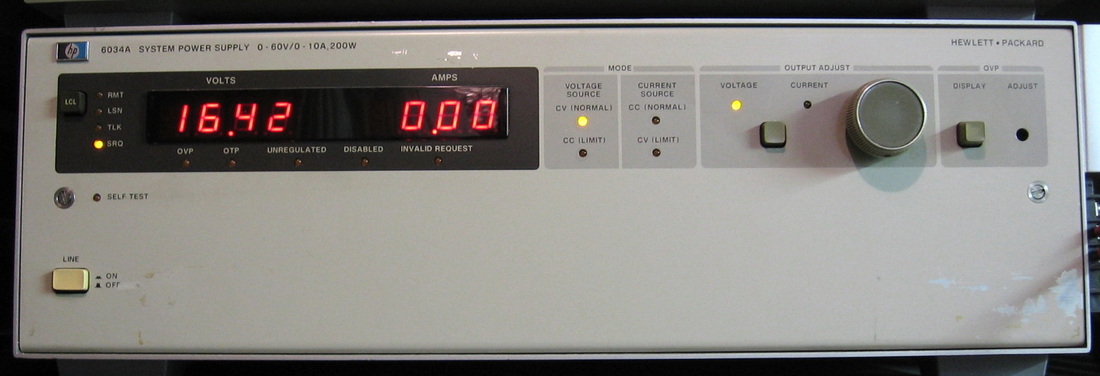
HP 6034A: One of HP's first switching power supplies. Will do up to 60V and 10A. Autoconfigures to keep the total power < 200W. Extensive self-test. I'm using this in the two wire configuration with the sense leads connected to the output terminals at the source. So I do get a voltage drop with high current draw. But at least the 10 amp capability is nice. (PDF) Grade: B+
This unit produced no voltage among other things. The switching FETs had shorted from source to gate and blew up everything in its path. Had to rebuild the driving circuitry to the gate and install new FETs. The optical encoder also needed new light bulbs and the over-voltage protection circuitry was malfunctioning because a wire had come off.
This unit produced no voltage among other things. The switching FETs had shorted from source to gate and blew up everything in its path. Had to rebuild the driving circuitry to the gate and install new FETs. The optical encoder also needed new light bulbs and the over-voltage protection circuitry was malfunctioning because a wire had come off.

HP 6113A: Precision power supply. HP made a few different models of these - mine is 10V, 2A, which is a bit obnoxious. However, the regulation is on the order of 0.001%, the stability is less than 0.01% over 8 hours and the ripple is less than 40 uV RMS. You would be hard pressed to find even a modern power supply that good. The "secret" is that they put the transistors controlling the feedback regulation inside an oven. This approach is similar to the Power Designs 2005 model described later on this web page. Built all with discrete transistors, it is everything you would expect from a 1968 piece. My only complaint is the thumbwheel switches which give your thumbs a good workout. (PDF) Grade: A-
The seller advertised this piece as producing 2.5V output regardless of setting. But, for twenty bucks, why not take a chance? Sure enough, the voltmeter read about 2.5 VDC and would only change to zero if I turned down the current limit. But after spending about an hour checking the various transistors, it dawned on me to hook up a scope to the output. As I have commented in the repair notes below, one should always check a power supply with an oscilloscope, because an ordinary DC voltmeter will just show you the average voltage even if the output is varying. And that's just what was occurring - a 10V AC signal at a frequency of about 10 kHz was the output of the 6113A regardless of front panel setting. Bottom line was one of the 1450 uF electrolytics right at the output had dropped down to about 100 pF and was causing something to oscillate. A new 1000 uF cap was the cure, but I probably should replace the five or so electrolytics that still remain in this unit.
The seller advertised this piece as producing 2.5V output regardless of setting. But, for twenty bucks, why not take a chance? Sure enough, the voltmeter read about 2.5 VDC and would only change to zero if I turned down the current limit. But after spending about an hour checking the various transistors, it dawned on me to hook up a scope to the output. As I have commented in the repair notes below, one should always check a power supply with an oscilloscope, because an ordinary DC voltmeter will just show you the average voltage even if the output is varying. And that's just what was occurring - a 10V AC signal at a frequency of about 10 kHz was the output of the 6113A regardless of front panel setting. Bottom line was one of the 1450 uF electrolytics right at the output had dropped down to about 100 pF and was causing something to oscillate. A new 1000 uF cap was the cure, but I probably should replace the five or so electrolytics that still remain in this unit.
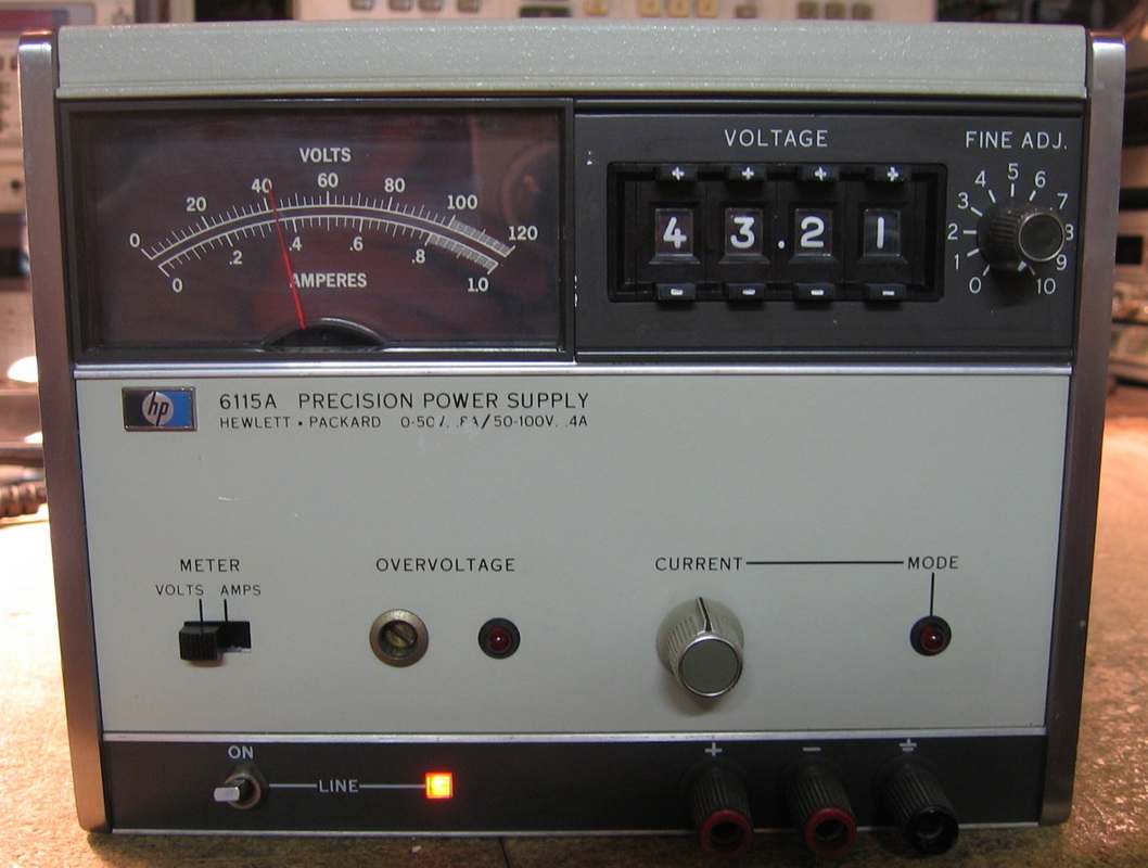
HP 6115A: Precision power supply. This is the big brother of the HP 6113A shown above. But this time, the voltage goes up to a little more reasonable 100 volts. The 6115A will do 0.8A at 50V and 0.4A at 100V. The specs are similar, but not quite the same, as the 6113A. While the 6113A has more digits of resolution, the 6115A is more accurate, achieving a 0.025% + 1 mV spec. Unlike the 6113A, there is no oven in the 6115A. The accuracy is provided by a 1N829 temperature compensated Zener (0.0005% per deg C) and a bunch of 0.1%, 0.025% and 0.01% precision resistors. No finger-hurting thumbwheels on this one; simple + and - buttons change the voltage. Has the usual over-voltage control/crowbar and current limiting pot. My only complaint (because I have to complain about something) is why did HP use red binding posts for both plus and minus? Couldn't they have used red, black and green for plus, minus and ground like everyone else? This supply had a long lifetime at HP. The manual I have is dated 1972, but my unit was made in 1985. (PDF) Grade: A
Advertised by a pseudo-test equipment dealer as being returned by the previous buyer because the volt/amp meter switch was defective and the unit was noisy. The meter switch was easy cleaned, so I turned my attention to the noisy output. At least that is what I thought the seller was referring to. But the output was perfectly clean (both with and without a load) and my Racal 9301 AC voltmeter measured 30 uV RMS, below the 40 uV spec. It was only when my finger happened to glance across the + and - buttons for the digits did I see the problem. The switches were noisy, not the output. A guy on eevblog posted a very nice tutorial on how to take the sealed switches apart, clean them, and reassemble everything. I simply followed his steps and the problem was solved.
Advertised by a pseudo-test equipment dealer as being returned by the previous buyer because the volt/amp meter switch was defective and the unit was noisy. The meter switch was easy cleaned, so I turned my attention to the noisy output. At least that is what I thought the seller was referring to. But the output was perfectly clean (both with and without a load) and my Racal 9301 AC voltmeter measured 30 uV RMS, below the 40 uV spec. It was only when my finger happened to glance across the + and - buttons for the digits did I see the problem. The switches were noisy, not the output. A guy on eevblog posted a very nice tutorial on how to take the sealed switches apart, clean them, and reassemble everything. I simply followed his steps and the problem was solved.
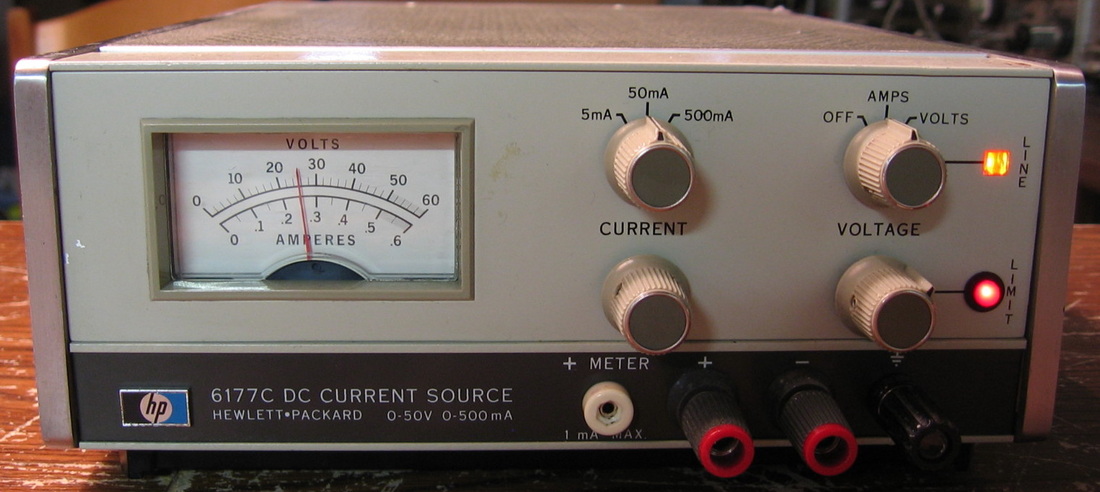
HP 6177C: A basic 500 ma current source, no-load voltage to about 50V. Really very nice to simply dial in the current you want. No messy power supplies, resistors, and voltmeters. Can also charge batteries if you like. Really a "must" for any well-equipped lab. (PDF) Grade: B+
Remounted the meter, replaced broken output connector.
Remounted the meter, replaced broken output connector.
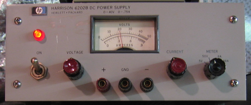
HP 6202B: Harrison and/or HP built a dozen different varieties. This one will do 40 V at 0.75 A. Totally bulletproof. These things go for <$25 if you shop around. I would recommend them to anyone who needs a basic P/S. (PDF) Grade: B
Simple blown pass transistor. I've gotten pretty good at replacing those!
Postscript: Umpteen years later, the previously replaced pass transistor blew again. Not sure if I caused it, because I was turning the supply on and off dozens of times while trying to debug another piece that was hooked up to it. The first transistor I pulled out of the junkbox only had a beta of 7 and when I put it in the 6202B, I was only getting about half the rated current out. The next transistor I tried, an RCA 40636, had a beta of about 50 and the 6202B achieved about 0.9 A out, exceeding specs.
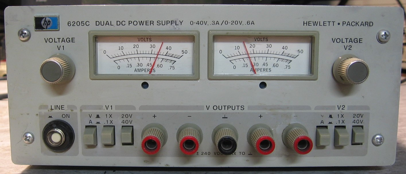
HP 6205C: Dual power supply, selectable ranges of 20V @ 600mA or 40 V @ 300mA. I used to have the 6205 "B" model, but gave it away. I am glad to see that HP made two improvements on the "C" version: 1) 10-turn front panel pots and 2) the banana jacks in a "+ - G" configuration instead of the annoying "+ G -" which won't accept a standard dual-banana plug. Other than that, it's a pretty bulletproof design with no frills (such as adjustable current limiting). (PDF) Grade: B+
This was only $50 shipped, condition unknown. It is getting harder and harder to find old test equipment that 1) I don't already have, or 2) isn't ridiculously overpriced by sellers that haven't a clue, so I was happy to get the 6205C. I would have been even happier if it was broken, but alas, it worked fine once I freed up the stuck pushbutton switches with some contact cleaner. The right channel's meter read a tad low on the voltage setting and there were no adjustment pots for it, so I padded the relevant resistor in the meter circuit.
This was only $50 shipped, condition unknown. It is getting harder and harder to find old test equipment that 1) I don't already have, or 2) isn't ridiculously overpriced by sellers that haven't a clue, so I was happy to get the 6205C. I would have been even happier if it was broken, but alas, it worked fine once I freed up the stuck pushbutton switches with some contact cleaner. The right channel's meter read a tad low on the voltage setting and there were no adjustment pots for it, so I padded the relevant resistor in the meter circuit.
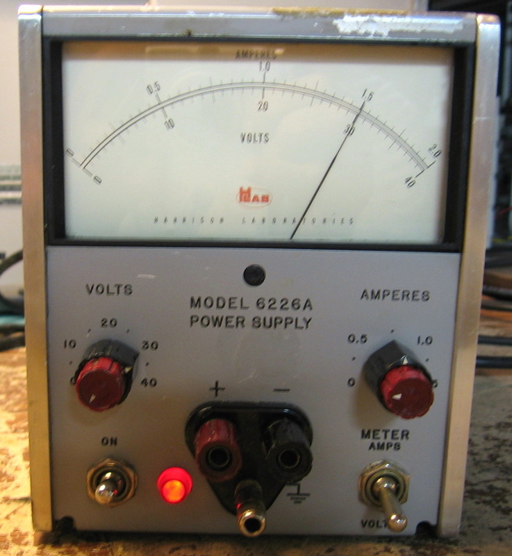
HP 6226A: Another one of a variety of Harrison single output power supplies. This one is rated for 36V @ 1.5A but will do 50V @ 2A. The transformer makes a nice humming noise. It draws 25W with no load due to Harrison's tendency to stick high wattage power resistors in the circuit for no apparent reason. Maybe the germanium transistors of that era needed to stay warm. (OM) Grade: C+
Despite being serial number 101, manufactured in 1962 and with a cracked resistor and many bulging capacitors, this thing actually worked when I received it. I replaced the bad resistor and all the electrolytic capacitors for good measure. And of course the service manual schematic didn't match my unit (what else is new?).
Despite being serial number 101, manufactured in 1962 and with a cracked resistor and many bulging capacitors, this thing actually worked when I received it. I replaced the bad resistor and all the electrolytic capacitors for good measure. And of course the service manual schematic didn't match my unit (what else is new?).
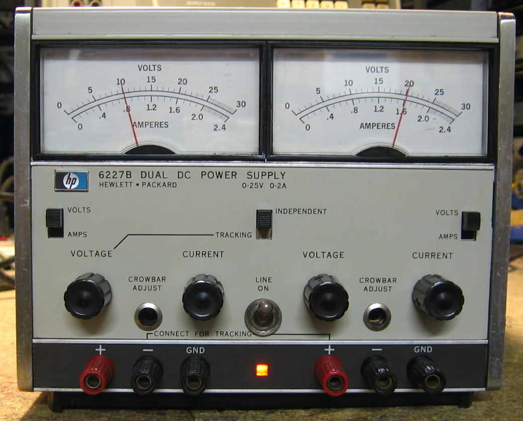
HP 6227B: Dual 50 watt power supply. The 6227B has two independent 25V, 2A power supplies. They can also be set to tracking mode so that the right (slave) power supply follows the left (master). Also has SCR-based overvoltage crowbars whose level can be set from the front panel. The specifications are OK, nothing spectacular. It weights about 25 pounds and consumes about 45 watts with the voltages set to zero. I would give this a grade of "B" for "Boring," but the fact that HP put the plus and minus binding posts next to each other, rather than putting the ground post between them, earns them a slight positive adjustment. (PDF) Grade: B+
This item was offered for $40 as a parts unit because it had been dropped onto the floor and the whole frame was severely bent out of shape. The seller also indicated that the V/A meter switch on the slave supply didn't work. Fortunately, when I received it, the slave supply did output voltage, so the fact that the meter read zero really was due to the V/A switch. The switch body took some damage in the fall to the floor, but I managed to bend things back, squirt in some contact cleaner, and it seems OK now. The big repair on this unit, however, was the chassis. The side frames had been bent so badly that one of them actually cracked in half. But HP used the same basic chassis components in a lot of their 1970 vintage units and I had a nice straight set of side frames in the junk pile. In they went. Most of my HP power supplies easily exceed their maximum ratings. In fact, the upper range of the meter scales are grayed out meaning that the supply will work, but the specs may not be met. I can get to >30V using resistance programming on the back panel of the 6227B, but under front panel control, 25V is all I get. R16 on the 6227B are padding resistors, hand-selected at manufacture, that control the voltage going into the main comparator that drives the pass transistors. The 13.1K and 19.1K resistors on the master and slave boards were both changed to 4.7K. Now I get the full 30V out of both supplies.
This item was offered for $40 as a parts unit because it had been dropped onto the floor and the whole frame was severely bent out of shape. The seller also indicated that the V/A meter switch on the slave supply didn't work. Fortunately, when I received it, the slave supply did output voltage, so the fact that the meter read zero really was due to the V/A switch. The switch body took some damage in the fall to the floor, but I managed to bend things back, squirt in some contact cleaner, and it seems OK now. The big repair on this unit, however, was the chassis. The side frames had been bent so badly that one of them actually cracked in half. But HP used the same basic chassis components in a lot of their 1970 vintage units and I had a nice straight set of side frames in the junk pile. In they went. Most of my HP power supplies easily exceed their maximum ratings. In fact, the upper range of the meter scales are grayed out meaning that the supply will work, but the specs may not be met. I can get to >30V using resistance programming on the back panel of the 6227B, but under front panel control, 25V is all I get. R16 on the 6227B are padding resistors, hand-selected at manufacture, that control the voltage going into the main comparator that drives the pass transistors. The 13.1K and 19.1K resistors on the master and slave boards were both changed to 4.7K. Now I get the full 30V out of both supplies.
Covid-19 Bonus Rant: I know what your are thinking - this guy is now going to pontificate on social issues, not just test equipment? Sorry to disappoint you, but no. My only comment is that I have seen a marked decline in test equipment offerings on eBay over the past year of Covid-19. One can speculate as to why, but one obvious reason might be that people have not been at their jobs and disposing of surplus equipment might have taken a back seat to other duties. And so in order to feed my compulsion to fix old test equipment, I've had to buy things that I really, really, really don't need, not my usual really don't need. The HP 6227B described above is a perfect example, hence this Bonus Rant.
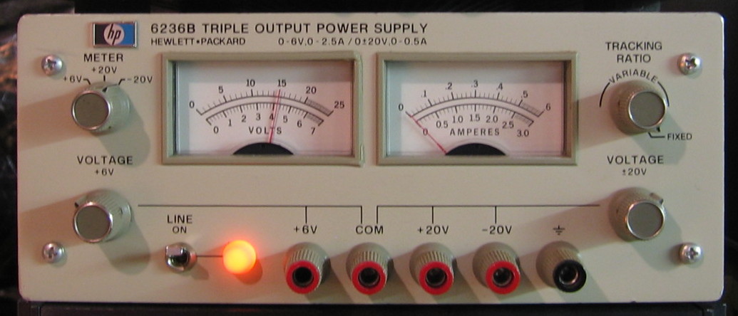
HP 6236B: 5, 20, -20 VDC triple output supply. The +/-20 V supplies can autotrack. Does about 2 A at 5V and 0.5 A at 20 V. If you are going to play around with op-amps, it's nice to have the plus and minus supplies. A Martha Stewart "good thing." (PDF) Grade: A-
Got two of these in one buy. The "better" one's meters had been pushed into the chassis and some of the output posts had broken off. I salvaged parts out of the second unit. The second unit had been reworked extensively by someone with no talent. I rejuvenated it to working condition and gave it to a friend with the caveat "never leave this thing powered up out of your sight."
Postscript: Many years later I noticed that there is a 0.1 uF Rifa suppression cap on the power line. Rifa caps are essentially time bombs waiting to explode. Even though this one was after the power switch, so that I need not worry if the 6236B is plugged in but off, I replaced it with a non-Rifa brand.
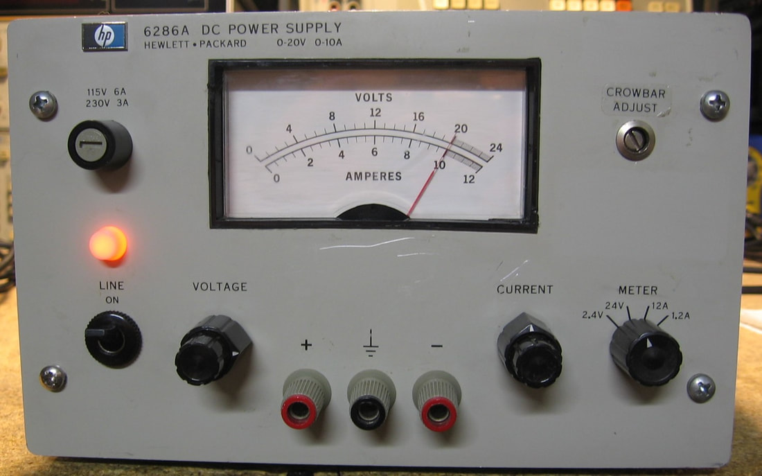
HP 6286A: DC Power Supply: The 6286A is a 20V, 10A linear power supply built by HP for about 30 years (mine was built in 1981). I suspect one can trace its lineage back to Harrison power supplies that HP sold back in the 60's. Unlike many other higher wattage supplies, this one is rated for the full current at the maximum voltage. Other supplies have specifications like 0 to 60V, 0 to 10A, 200W total meaning that the voltage and/or current is automatically throttled back to keep the total power below the 200W rating. The 6286A keeps the power dissipation on the pass transistors low by pre-regulating the input voltage with SCRs. Thus it gets away with convection cooling and no fan. But you can tell from the several brown discolored spots on the board that the unit runs hot by design. Like typical HP pieces of the 1960's and 1970's, it is built like a tank and weighs about 30 lbs. It does hum a bit, but I guess that is normal for a beast like this. (PDF) Grade: B+
The seller offered a cryptic description along the lines of "only half output and no negative voltage." Didn't make much sense to me, but the price was right ($25 + shipping). When received, the meter bezel had cracked in two places (maybe during shipment) and the meter was rattling loose inside. A little epoxy and black paint put the meter back where it belonged. Electrically, the unit was fine and only very slightly out of adjustment.
The seller offered a cryptic description along the lines of "only half output and no negative voltage." Didn't make much sense to me, but the price was right ($25 + shipping). When received, the meter bezel had cracked in two places (maybe during shipment) and the meter was rattling loose inside. A little epoxy and black paint put the meter back where it belonged. Electrically, the unit was fine and only very slightly out of adjustment.
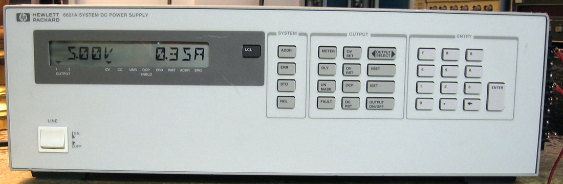
HP 6621A: The HP 6621A consists of two independent 80W power supplies. Each can operate in one of two modes that are automatically selected: 1) 7V, 10A or 2) 20V, 4A. The supply is intended to be used primarily through the GPIB interface, but can be operated adequately from the front panel. Mine has Option 750 which brings an extra connector out the back with signals related to various faults within the supplies (the intent is then to use these signals to protect the load with relays for example). Agilent still sells this model for about $9,000, along with the 6622A, 6623A, 6624A, ... which have up to four outputs using either 40W or 80W supplies. My unit is extremely accurate (no load voltage accuracy to < 1 mV) and I've measured about 1.2 mVrms output ripple on my wideband (10 Hz - 10 MHz) HP 3400A RMS Voltmeter without even doing the measurement accurately (specific load, shielded cables, etc.). All in all, a very nice example of typical HP over-engineering. Unlike many of my recent buys, the 6621A is actually going to be part of my main stack of operational equipment rather than thrown on a random pile. (PDF) Grade: A
This item was offered as "powers up, LCD display dark," and the seller was accurate in his description. A quick check of the controller board supplying the DC voltage to the LCD showed 0V at the 5V test point. This was caused by an open 4A fuse on the controller board. Once that was replaced, the LCD sprang to life and I dialed in 5V on the panel and measured 5V on the output. However, when I tried to press the other front panel buttons (e.g., to set the current), only a few of them responded. So I pulled the front panel only to find the ribbon connector tilted making contact with about 1/4 of the pins. A simple fix indeed. The only other thing left to do was run the 8 output lines from the back panel around to a connector block at the front right of the unit (look carefully at the photo) so that I can actually use this thing.
Postscript: Preemptively replaced the Rifa 0.22 uF Y-capacitor on the power receptacle with a non-Rifa branded 0.22 uF Y-capacitor. In addition to this cap, there were six other various Rifa 0.022 uF and 0.0015 uF Y-caps going between the DC output and chassis ground. Not quite sure why they needed to use Rifa caps, but all were replaced with non-Rifa 0.01 uF Y-capacitors as I don't think the actual uF value is critical.
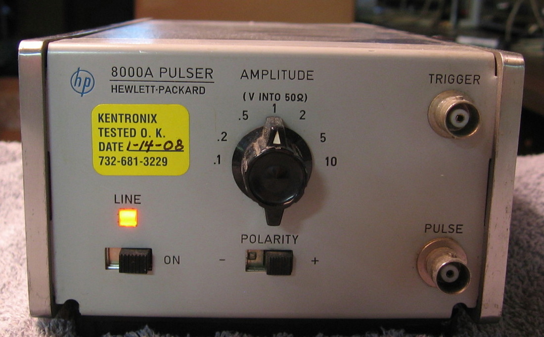
HP 8000A: Can find nothing about this. It puts out a 1 nsec rise time pulse at 100,000 pulses per second. That's it.
Postscript: Came across the op/svc manual on BAMA (finally) and HP says this device was built to test the dynamic response of wideband amplifiers and components. It has <1 nsec rise time (I measured it at about 850 psec) and is flat to within 2% over 100 nsec nominal pulse width. It uses a step-recovery diode which I'm sure is just as hard to get as it was originally to find out anything about this pulse generator! (PDF) Grade: B
Postscript: Came across the op/svc manual on BAMA (finally) and HP says this device was built to test the dynamic response of wideband amplifiers and components. It has <1 nsec rise time (I measured it at about 850 psec) and is flat to within 2% over 100 nsec nominal pulse width. It uses a step-recovery diode which I'm sure is just as hard to get as it was originally to find out anything about this pulse generator! (PDF) Grade: B
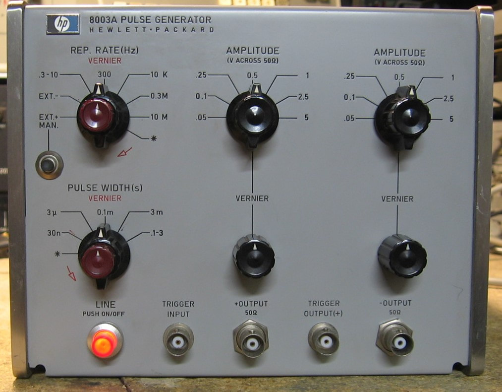
HP 8003A: Basic 10 MHz pulse generator. Will do 0.3 Hz to 10 MHz repetition rate, 20 ns to 3 s pulse width, 0.2 V to 5 V amplitude into 50 ohms with 5 nsec rise/fall times and simultaneous positive and negative outputs. Don't let the plain front panel fool you, this is actually a wonderful piece that is built like a tank (1969) and straightforward to use. Despite being more than 50 years old, it looks like it came out of a museum. There's hardly a mark on it and the insides are pristine. It is a very straightforward design without any integrated circuits or unobtainable tunnel diodes. When I received it, only a few squirts of contact cleaner in the pots/switches were necessary and the unit was perfectly functional and within spec. (PDF) Grade: A
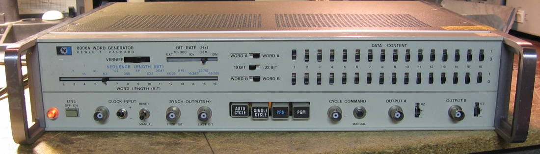
HP 8006A: Two channel, 16/32 Bit 10Hz-10MHz word generator. Pretty straightforward and a little easier to use than the HP 8018A and HP 8080A. It does, however, have two quirks. First, the positive amplitudes are fixed at 2.5V and the negative at -5.0V. Secondly, when using RZ mode instead of NRZ, the pulses have a fixed 45 nsec wide width. At first, I thought the unit was broken because I was looking at 1 kHz pulses and expected the RZ widths to at least be visible on the scope! (PDF) Grade: B
Flawless upon receipt except for a broken front panel toggle switch which was suitably replaced.
Postscript: With over 300 pieces of test equipment, something always eventually needs fixing. This time, it was the HP 8006A's turn. The output was dead on all channels both in word mode and random mode. This implied that the master clock wasn't running and a quick check of the test point confirmed that. It was fairly easy to trace it to the PNP clock amplifier transistor. The part number was 1853-0027 which googled to a custom HP transistor with no equivalent. The first junkbox transistor I tried didn't have the frequency response I guess, because I only got about one volt of clock signal out of it (I'm guessing I need a TTL level). So where am I going to get an 1853-0027? I figured HP must have used them in other pulse generators, for instance the spare HP 8012B parts unit sitting in the junk pile. And so they did. I also used a larger heat sink this time to keep it from burning up again.
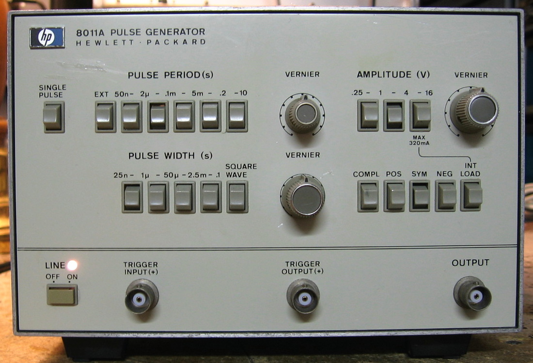
HP 8011A: Basic no-frills 20 MHz pulse generator. Unlike the HP 8012B, this one uses pushbuttons instead of the problematic slide switches. Has a fixed 10 nsec rise time, positive/symmetric/negative amplitudes and a whopping 16V maximum output. (PDF) Grade: C+
The seller claimed that the unit showed no signs of life on power up. So he "verified" that 5V was being supplied to a presumably burnt out front panel bulb. He then claimed that he wasn't sure if the unit was working. So let's see, he knew enough to take off the covers and put a voltmeter across the bulb, but he didn't bother to hook up a scope to the output? And this is from a test equipment dealer! Upon receipt, the unit's output was all screwed up - wrong voltages, some frequencies didn't work, etc. The fault seemed to be located around a set of 3 ICs which shape the Schmitt trigger pulse generator on its way to the output amplifier. To simplify things for exposition, consider the three ICs as being powered by the 14V rail through a 121 ohm resistor to a 5.1V zener to ground (Vcc is pulled from the resistor-zener junction). What was happening is that too much current was being drawn and Vcc was dropping through the resistor to about 3.5V. Thus the IC outputs never made it high enough to get over the quiescent point of the output amplifiers. I pulled the three ICs and ordered new ones. While I was waiting, I put the ICs on a breadboard and tested the logic. I could find nothing wrong with them. Moreover, when I re-installed the ICs and lifted the one output pin going to the amplifier, all of the IC functionality was correct. So things didn't look good for my bad IC assumption. To make a long story short, I had already checked the 5.1V zener, but now I put an ohmmeter across the 121 ohm resistor: 350 ohms. That can't be good. The resistor actually measured 446 ohms when I pulled it. All I had in the junkbox was a 2W, 150 ohm resistor, so that would have to do. And do it does. The thing now works flawlessly, calibrated properly and passed all the performance tests. I also replaced the 5V bulb and the amplitude vernier pot (taken from a spare HP 8012B parts unit) that was very noisy and I removed two plastic circular 1-10 scales that were glued to the front panel. The reason I've graded this piece a C+ is because of the heat. It probably has to dissipate >25W and it does it one transistor and resistor at a time. Virtually every part runs too hot for my taste.
The seller claimed that the unit showed no signs of life on power up. So he "verified" that 5V was being supplied to a presumably burnt out front panel bulb. He then claimed that he wasn't sure if the unit was working. So let's see, he knew enough to take off the covers and put a voltmeter across the bulb, but he didn't bother to hook up a scope to the output? And this is from a test equipment dealer! Upon receipt, the unit's output was all screwed up - wrong voltages, some frequencies didn't work, etc. The fault seemed to be located around a set of 3 ICs which shape the Schmitt trigger pulse generator on its way to the output amplifier. To simplify things for exposition, consider the three ICs as being powered by the 14V rail through a 121 ohm resistor to a 5.1V zener to ground (Vcc is pulled from the resistor-zener junction). What was happening is that too much current was being drawn and Vcc was dropping through the resistor to about 3.5V. Thus the IC outputs never made it high enough to get over the quiescent point of the output amplifiers. I pulled the three ICs and ordered new ones. While I was waiting, I put the ICs on a breadboard and tested the logic. I could find nothing wrong with them. Moreover, when I re-installed the ICs and lifted the one output pin going to the amplifier, all of the IC functionality was correct. So things didn't look good for my bad IC assumption. To make a long story short, I had already checked the 5.1V zener, but now I put an ohmmeter across the 121 ohm resistor: 350 ohms. That can't be good. The resistor actually measured 446 ohms when I pulled it. All I had in the junkbox was a 2W, 150 ohm resistor, so that would have to do. And do it does. The thing now works flawlessly, calibrated properly and passed all the performance tests. I also replaced the 5V bulb and the amplitude vernier pot (taken from a spare HP 8012B parts unit) that was very noisy and I removed two plastic circular 1-10 scales that were glued to the front panel. The reason I've graded this piece a C+ is because of the heat. It probably has to dissipate >25W and it does it one transistor and resistor at a time. Virtually every part runs too hot for my taste.
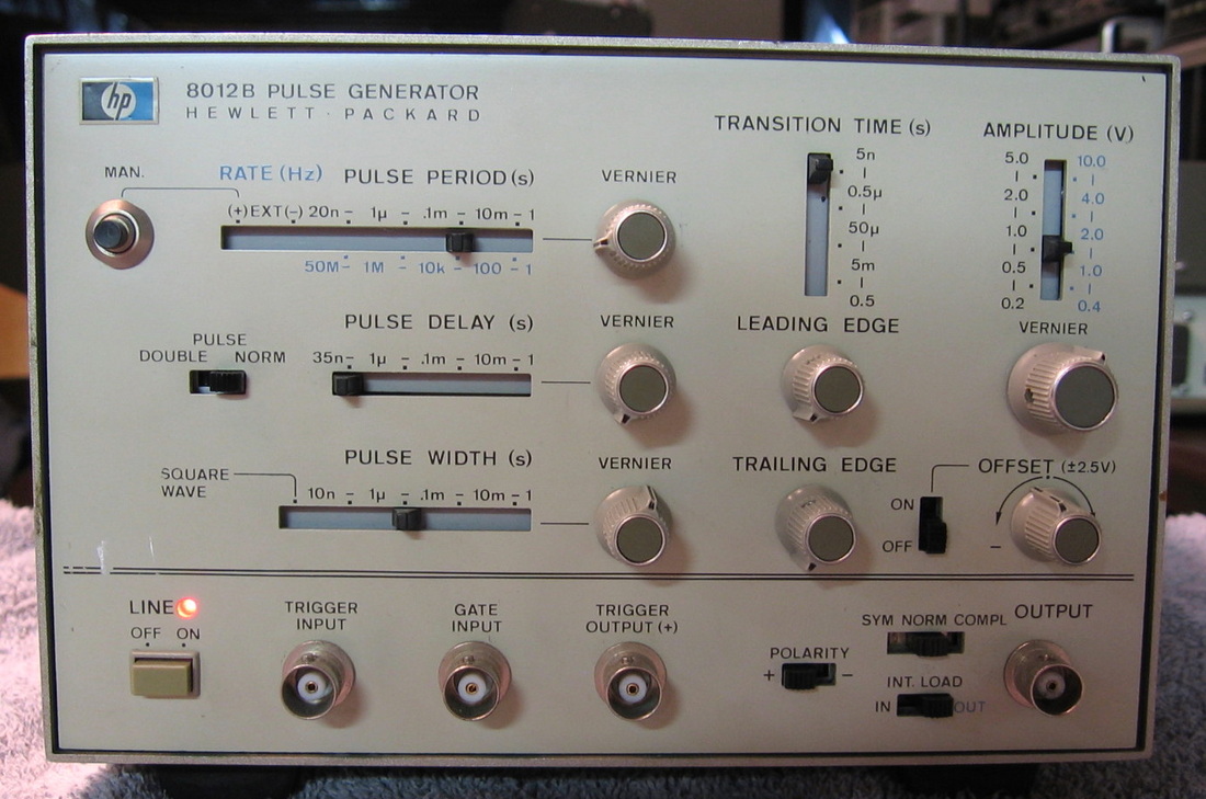
HP 8012B: Basic no-frills 50 MHz pulse generator with HP's odd scheme of slide switches. The thought was to "unconfuse" the operator by suggesting that no lower slide switch be to the right of the one above it. All it really does is confuse. (OM) Grade: B-
Another "two-for-one" deal. Both not working. The "better" one I chose to fix using parts from the second. Some of the resistors in the attenuator circuitry were gone. Not bad, but simply not there. Also replaced blown diode in 17V P/S circuit. Exchanged a few pots, knobs, etc.
Another "two-for-one" deal. Both not working. The "better" one I chose to fix using parts from the second. Some of the resistors in the attenuator circuitry were gone. Not bad, but simply not there. Also replaced blown diode in 17V P/S circuit. Exchanged a few pots, knobs, etc.
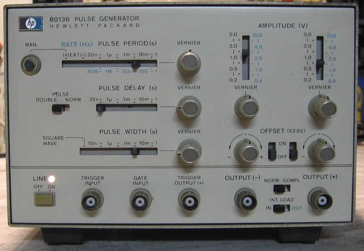
HP 8013B: Basic no-fills 50 MHz pulse generator, similar to the HP 8012B. Whereas the 8012B has a single output with user adjustable rise and fall times, the 8013B has normal and complementary outputs with fixed 3.5 nsec transition times. Otherwise, the basic functionality, performance and somewhat cumbersome user interface is the same. (PDF) Grade: B-
This piece arrived in condition unknown. The 17V and -17V power supplies were spot-on, but there were no pulses coming out of either of the two outputs. The trigger output showed some life, so at least the basic rate generator was working. HP pulse generators of this era (8012B, 8013B, 8082A, etc.) use these slide switches which have little spring contacts (sort of like those in the cam switches of Tektronix scopes) that drag across gold traces on the front panel board. These are guaranteed to be maintenance nightmares even long before the gold gets scraped off. And since the purpose of these switches mostly is to apply voltages to the proper pulse generation circuitry, when they go, so goes your output. Several hours of dissection and epoxying put the cracked plastic and loose misaligned spring contacts back in order and the 8013B sprang to life. The period, delay and width vernier pots were pretty much shot and I found a bunch of replacements in my junkbox, so in they went. I ran through the calibration procedure just to make sure everything electrically was correct - and it was.
This piece arrived in condition unknown. The 17V and -17V power supplies were spot-on, but there were no pulses coming out of either of the two outputs. The trigger output showed some life, so at least the basic rate generator was working. HP pulse generators of this era (8012B, 8013B, 8082A, etc.) use these slide switches which have little spring contacts (sort of like those in the cam switches of Tektronix scopes) that drag across gold traces on the front panel board. These are guaranteed to be maintenance nightmares even long before the gold gets scraped off. And since the purpose of these switches mostly is to apply voltages to the proper pulse generation circuitry, when they go, so goes your output. Several hours of dissection and epoxying put the cracked plastic and loose misaligned spring contacts back in order and the 8013B sprang to life. The period, delay and width vernier pots were pretty much shot and I found a bunch of replacements in my junkbox, so in they went. I ran through the calibration procedure just to make sure everything electrically was correct - and it was.
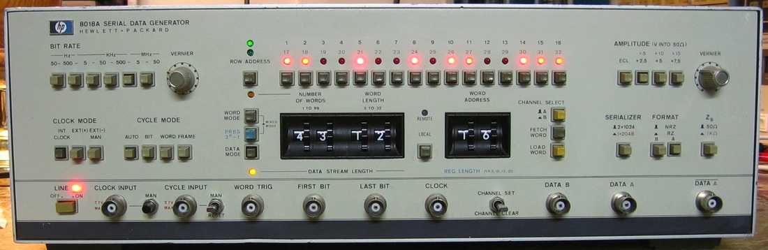
HP 8018A: 50 MHz digital data generator capable of outputting a user defined 2048 bit string. Also has several pseudorandom generators that can be interlaced with the user defined string. Can be configured as a single 2048 bit channel or two 1024 bit independently programmed channels. Outputs a variable positive level or a fixed ECL level, RZ or NRZ pulses, 50 or 1000 ohm output impedance, and has lots of input/output triggers and gates. This unit has Option 001, GP-IB. Although relatively easy to program from the front panel, I can see why many would prefer Option 001. The 8018A is very similar to the HP 8080A I have, but is more flexible (and has a lower clock rate). For the twenty bucks I paid for this, you have to admit it has a very high button-to-dollar ratio. (PDF, OM) Grade: B
This unit was made by HP-Germany, another fine example of "German Engineering." Yeah, right. You Mercedes owners had better think twice. The piece runs extremely hot (155W draw) and they put an anemic little fan, about the size of a CPU cooler, right in the middle of the chassis. As far as I can tell, all it does is stir up the air inside. When received, two of the three power supplies were dead. This was traced to pass transistors not making contact with their sockets (see the writeup on the HP 3314A). And that pretty much summed up the rest of the piece. All the boards needed reseating and all the front panel controls needed contact cleaner. The amplitude vernier shaft was sheared off and replaced with a new pot. Two of the pushbuttons were missing and bought from Tucker. The burned out power bulb was replaced with an LED. Everything works fine now and meets the performance checks and specifications.
Postscript: As a precautionary measure, replaced the Rifa branded 0.47 uF X-capacitor and two 0.001 uF Y-capacitors. Otherwise, it is only a matter of time before they blow up. In particular, the 0.47 uF already had a large crack in the case.
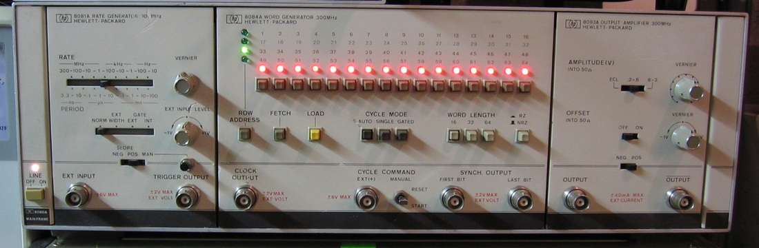
HP 8080A: Mainframe with 8081A, 8083A and 8084A modules configured as a 300 MHz, 64 bit word generator. The 300 MHz capability is nice, but the HP 8175A is more versatile. (OM) Grade: B
The standard faulty P/S supply requiring a new switching transistor and emitter resistor.
Postscript: Truly Rifa madness in this one! There were six Rifa suppression capacitors in the power supply. All were replaced with non-Rifa caps.
The standard faulty P/S supply requiring a new switching transistor and emitter resistor.
Postscript: Truly Rifa madness in this one! There were six Rifa suppression capacitors in the power supply. All were replaced with non-Rifa caps.
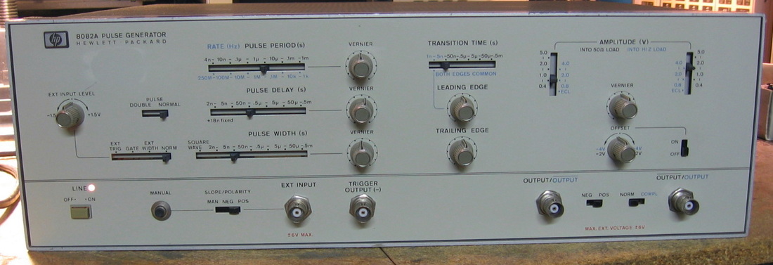
HP 8082A: 250 MHz pulse generator, the big brother of the HP 8012/13 series. All pretty self-explanatory by looking at the photo. Completely analog in design, using a few HP hybrid chips, there is no comparison to the precision offered by something like my HP 8160A. But unlike all the other pulse generators I have, this is the only one that will do a 1 nsec rise time pulse. And that's the reason I forked over $26 to buy it. The rise time measured about 700 psec on my HP 53310A modulation analyzer (in time-interval mode). The 8082A was built by HP-Germany, along with many of their other HP 8xxx series stuff. It uses the horizontal/vertical slide switches which I absolutely detest; thankfully, HP abandoned those soon enough. The switches, which simply drag contacts along gold traces on the underlying PC board, are somewhat open to the outside and easily get dirty. And if that's not enough, eventually the contacts scrape away the gold. Otherwise, it's a pretty decent unit. Oh, except for the drift when it is first turned on - I measured almost a 3% frequency change in the first 20 minutes. (PDF) Grade: B+
Advertised by the seller as "doesn't power up." Took it out of the box, plugged it in, worked flawlessly and passed all the performance tests. Thanks a lot, Mr. Seller - now I have nothing to do (well, I did pull the front panel apart and clean all the slider switches). Let me also take this opportunity to make a remark about the front panel paint. With most of the HP pieces I have, HP used a flat gray paint on the front panel which can easily be damaged if harsh chemicals are used to remove stubborn sticker residue. In more modern pieces, HP went to some sort of plasticized panel which is even more fragile. The HP 8082A and my HP 8018A use a gray crinkled paint that simply laughs at stickers and seems impervious to any chemicals. I wish they were all like that.
Postscript: A few years later I noticed the front panel power light was blown. Kind of strange because I really haven't used the piece at all after the initial repairs. A new 5V miniature bulb was therefore installed.
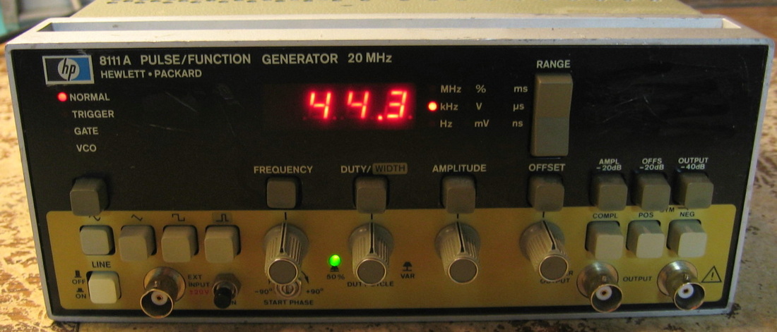
HP 8111A: HP-Germany designed 20 MHz function generator. Does sine, triangle and pulse waveforms with variable duty cycle/symmetry. Somewhat peculiar set of controls, but works as advertised. Which isn't particularly impressive because the specifications on this unit are simply horrid: +/-5% for frequency and amplitude accuracy (as a function of the numeric display), 1-3% distortion, etc. I suppose this thing makes a nice source for teaching how to use an oscilloscope, but I wouldn't dare use it when I needed accuracy. I'm not sure what HP was thinking since their HP 3314A is similar and has much better specs. Perhaps they simply were trying to hit a lower price point. (PDF) Grade: B-
I took a chance on this one because the 8111A, like the 8112A and 8116A, uses a set of HP custom ICs that are unobtainable (see the writeup in the "It's dead, Jim" section on my previous exploits with the 8112A). The seller advertised the unit as "doesn't power up," and that was almost correct. Upon inspection, and breathing a sigh of relief when I found the custom ICs happily in their sockets, the P/S was cycling on/off rapidly due to overcurrent on the -23 V supply. The culprit was a single 0.47 uF capacitor on the -23 V rail of the output board. I don't think I've ever seen a plain old ordinary capacitor shorted - there certainly were no outward signs. Anyway, a quick replacement and a tedious alignment restored the unit to spec. Cosmetically, it was in average shape. The 8111A, 8112A and 8116A all have a thin plastic coating on the front panel. Most of these start to buckle over time and mine was no exception. So I sat for over an hour carefully stripping away all of the plastic. Somewhat better look now.
Postscript: Took the cover off one day and saw a Rifa 0.01 uF suppression capacitor. It was replaced (with a non-Rifa brand) on the spot. Don't take chances with any old, gold colored Rifa caps - simply replace them before they blow up, which they are guaranteed to do soon.
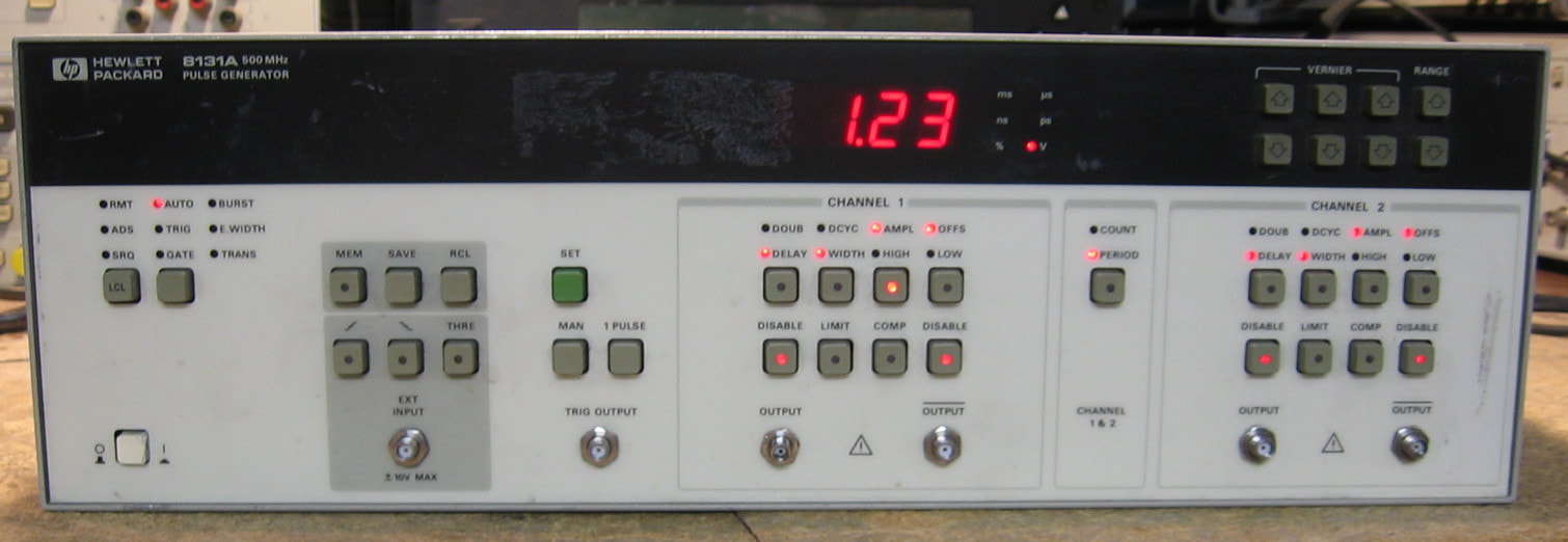
HP 8131A: Two channel 500 MHz pulse generator. Compare this piece to the HP 8082A and HP 8160A (both listed on this web page). The 8082A will do 250 MHz with 1 nsec rise times, but is not digitally programmable and requires a scope to set it precisely. The 8160A, on the other hand, is implemented digitally, but only does 50 MHz with 6 nsec rise times. The 8131A will do 500 MHz with a pretty amazing 200 psec rise time. There is also a mode which will accept up to a 1 GHz sine wave and will output a squared-up version of your input. My unit has the Option 020 which adds the second channel. Now for the bad news. The 8131A, like most HP pulse generators in the 8xxx series, was built by HP-Germany and as such contains numerous custom hybrid chips and a thoroughly unimpressive service manual. The custom chips are notorious for failing and in some instances, eg., HP 8112 generators, it's almost guaranteed that there are one (or more) failures. But for $77, I thought I would take a chance on the 8131A. Unfortunately, I too got burned on this one. For it looks as though the custom GaAs output amplifier hybrid on both channels is faulty. Kind of odd that both channels failed, unless the previous owner hooked up some cable of death to the output of channel #1, blew that up, and then in desperation, switched the cable to channel #2 and blew that up also. Now, these ICs are not totally dead, just badly misbehaving. You do get outputs on both channels, but the pulses have a lot of ringing and an incorrect DC level. Moreover, you have to crank up the amplitude to between 4.0 and 4.5 volts to even get an output pulse. However, everything else works: timing, modes, external triggers, etc. And I'm getting about 650 psec rise times on my HP 54522A and Tek TDS350 scopes consistent with their 500 MHz bandwidth, so I'll take HP 's word that the 8131A can generate 200 psec rise times. The front panel is a bit awkward and the manuals are terrible, so I'll give this piece a grade of B+ (assuming it worked properly). (PDF) Grade: B+
I basically just verified that the control voltages surrounding the two output amplifiers seemed correct and that the input to the hybrids (from the so-called transducer board) also seemed correct. Then I started crying.
A few days later I took the cover off one of the hybrid amplifiers and looked at it with a 10x magnifying glass. I saw several broken wires (less than the thickness of a human hair) confirming my suspicions that there is no hope of repair (at least by me).
HP 8131A Bonus Rant: The 8131A doesn't really belong in the "It's dead Jim" section below, nor does it really belong in the main collection. As a compromise, I am including the piece in the main collection, but not counting it as an actual item or including it in the "Some statistics" section below.

HP 8160A: Two-channel 50 MHz pulse generator, designed by HP-Germany but built in the USA. Unlike most (vintage) pulse generators that have analog knobs, this unit is programmed all digitally from the numeric front panel keypad. Simply punch in the period, width, delay, leading and trailing edge times and high and low amplitudes and you are good to go. Has the usual external gate and trigger functions and will also do double pulses. Selectable output impedances of 50 and 1000 ohms, similar to that found in the HP 8165A; however, the effect on output voltage of the output impedance is not what you would think since this thing is designed basically as a current source. HP also sold this in a single channel variant (less Option 020), but my $50 eBay purchase luckily was the two-channel version. HP also made the HP 8161A which has slightly better rise/fall times than the 6 nsec I am getting. The basic accuracy for most parameters is about +/-1%. One of the nicest features is that it will add the two channels together with a flick of a button. By varying the pulse delay parameters, one can then come up with a slew of interesting three step waveforms. The big surprise is when you take off the top cover and peer inside. Staring at you are 23 circuit boards, spaced about 1/4" apart with absolutely no free space anywhere to be found in the chassis. I have numerous other pulse generators and they all have a couple of boards at best. So why does the 8160A need 23 boards and why is it rated at 675VA? And why did it cost $25,000 in 1992? Ask the Germans. (PDF) Grade: A
First of all, the service manual is written in the distinct HP-Germany style which means a bunch of service block sections each containing some measurements and hints as to how to fix things. But the schematics and parts layout are complete. I don't like this style quite as much as the HP-USA service manuals which tend to walk you through things logically. Having now voiced my complaint, the unit was advertised as "doesn't power up" - my favorite kind of fault. Powered through the Sencore isolation transformer, the meter showed zero current being drawn when I hit the power button. So that usually means a switch or fuse or relay. I first pulled the processor board containing the two 1/3-AA size NiCd batteries that I suspected would have leaked by now. And I wasn't disappointed. So I meticulously cleaned up the acid residue and decided to run wires out the back panel to a battery holder to hold two regular AA NiCds. Not that these will get much charging, because the unit only supplies about 15 mA and only when it is powered on. I was sort of hoping that the battery acid might have shorted something causing the P/S to drop off. But a quick look at the schematic showed that nothing in the charging circuit really could have much effect elsewhere. So turning to the main supply, I opened up the switching P/S and found a blown 1A fuse on one of the three boards. Reaching into my drawer of fuses, I pulled out a 3A fuse and proclaimed "close enough." The 8160A now powered up, but the front panel was completely lit up (automatic startup condition) and unresponsive to any input. Then, of course, there was that strong burnt smell, which didn't last long because smoke started to pour out the left rear corner. I turned the thing off and pulled out what I thought was the offending board - the main regulator which takes the switching P/S outputs and generates about 10 other voltages. Everything looked fine, tested fine and I could find nothing wrong with the board. So I put it back in, powered it up and waited for the smoke so I could see exactly where it was coming from. No smoke this time, but the front panel was still locked up. I measured the 5V line and it read 4V. That explains why the uP was unresponsive to front panel keypresses. While I was pondering that, I saw a glow coming out of the (shielded) switching P/S. Peering through the vent holes, I saw what I thought was a neon light bulb. Funny, I didn't remember seeing a neon bulb when I replaced that 1A fuse. Looking more closely, it wasn't a neon bulb that was glowing bright orange - it was a 10 ohm, 20W wire-wound resistor that was lit up like a toaster. The 8106A has an inrush current limit circuit that consists of that 10 ohm resistor preceded by the 1A fuse. The fuse-resistor combination is bypassed by a relay which switches as soon as sufficient voltage is sensed on the main transformer. Only problem was that the relay never switched. So the thing was more than happy to dump about 3.5A through my 3A fuse into the 10 ohm resistor. Had I not stupidly replaced the 1A fuse with a 3A fuse, it wouldn't have been obvious what was happening. The 1A fuse would have just kept popping. Bottom line: a 681 ohm, 1W resistor in series with the relay coil opened up. I replaced the resistor (with six 3.9K 1/4W resistors in parallel from the junkbox), put in the proper 1A fuse, and voila. I was very fortunate because the toaster I made out of the resistor actually melted a portion of the adjacent relay and the adjacent main power switch. But they both survived as did the 10 ohm resistor. So everything works as expected now. The unit is a mechanical nightmare filled with relays, switches, cables and little connector boards with dozens of sharp pins on them (these connect adjacent boards because I guess they ran out of motherboard/edge connector pins). It is clear that things are a bit tarnished from the long period of inactivity as a few times the signal output was a bit off (but quickly cleared up). I cleaned a lot of what I could get to and it seems to be improving as I use it. The unit appears to be in spec from the limited performance tests, but someday I might try the calibration as soon as I can come up with two 15 pin extender boards and one 10 pin extender board all the same height. Oh, there are well over 100 pots/caps to adjust and I estimate at least six hours to do it right.
Postscript: One day, I entered 50 nsec for the A-channel pulse width and got 500 nsec out. Moreover, the pulse widths were all OK for values less than 50 nsec, but abruptly changed to 500 nsec the moment I entered 50 nsec. And it basically was flaky all over - for instance, a change in amplitude affected the pulse width. The B-channel, however was all good. I exchanged A- and B- channel width boards (the one of three that handles each channel's >50 nsec widths) and the problem moved with the exchange, so that narrowed it down to one board. Finally, I noticed that when I changed a B-channel parameter, that also affected the A-channel. All of this pointed to a problem with what HP called the "acceptor," on the A-channel width #3 board, which is just a fancy way of saying an address decoder. The acceptor is implemented with five CMOS 4000 chips and I had three out of five in my junkbox, so in they went. Turned it back on and everything works. Funny, but the little Chinese TES200 IC tester I have indicated all three of the pulls were OK. My guess is that the flip-flop was the faulty component and the tester isn't very good - the other two chips were simple combinatorial logic and it would be hard to fool the tester on those. Anyway, who cares - the 8160A works.
Postcript^2: Turned the 8160A one day and I heard a few pops followed by a terrible stench emanating out the back all the while the unit seemed to work just fine. Indeed, one of the notorious Rifa 0.22 uF suppression caps exploded. I replaced it temporarily with a 0.1 uF cap, but since it is part of the snubber circuitry across the main transformer in the switching power supply, I ordered the correct value and in it will go.
Postscript^3: I decided to replace all nine of the Rifa suppression caps in the P/S since if one exploded, others are sure to follow. Curiously, all nine caps read very high on the LCR meter - most by at least 50%. Now, the May 1979 HP Journal describes the 8160A's P/S this way: "accessibility and hence serviceability are good thanks to modular design with functionally separated plug-in boards." Yeah, right. The supply is crammed together with virtually no free space. It took me several hours to pull out the line filter board, A13, since it is directly soldered to the back of the AC receptacle and fuse holder that stick through the outside (non-removable) cover, and there is a riveted bracket in the way that has to be drilled out. And then when you try to lift the board out, there are several parts on the motherboard in the way that must be removed. "Serviceability?" I guess if you just want to probe parts of the boards, it is OK. "Accessibility?" Not a chance in hell. It's a bit of a shame because someone at HP must have given the designers a volume constraint on the P/S. The whole supply sticks out the back, but only about half of the back panel is interrupted. They might have made the supply a bit larger one would think.
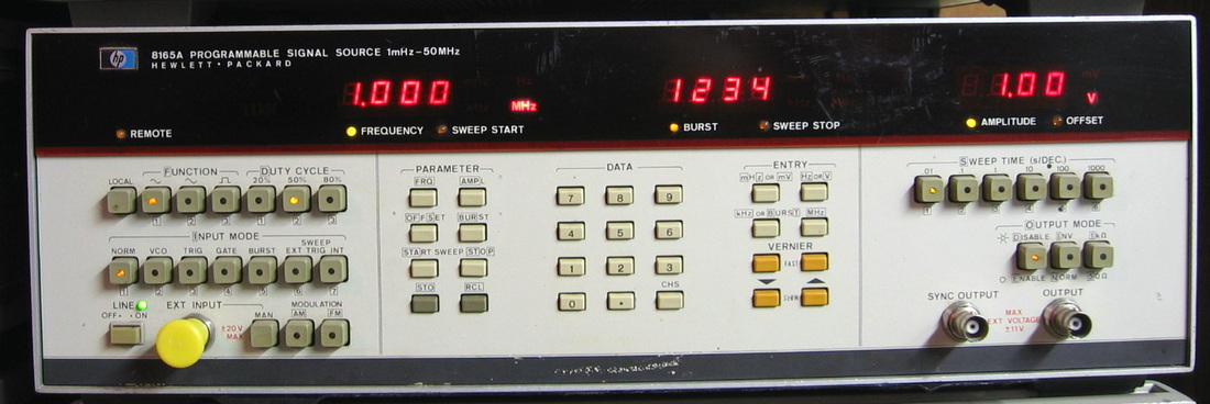
HP 8165A: Called a programmable signal source, this is a 50 MHz function generator producing sine, triangle, square. Actually is very capable, but does not have the parameter resolution of many other generators. Built by HP Germany. I've seen many of these go on eBay for very little money because nobody seems to know what they are. If you don't need precise control of frequency, they are a very good deal. (PDF) Grade: A-
This was not really a repair as much, but deserves note because all of the initial problems were corrected once I properly aligned the unit. I've never seen any HP piece this far out of whack. Also reworked the battery backup into a remote enclosed battery holder.
Postscript: Did a preemptive replacement of the Rifa suppression 0.022 uF capacitor.
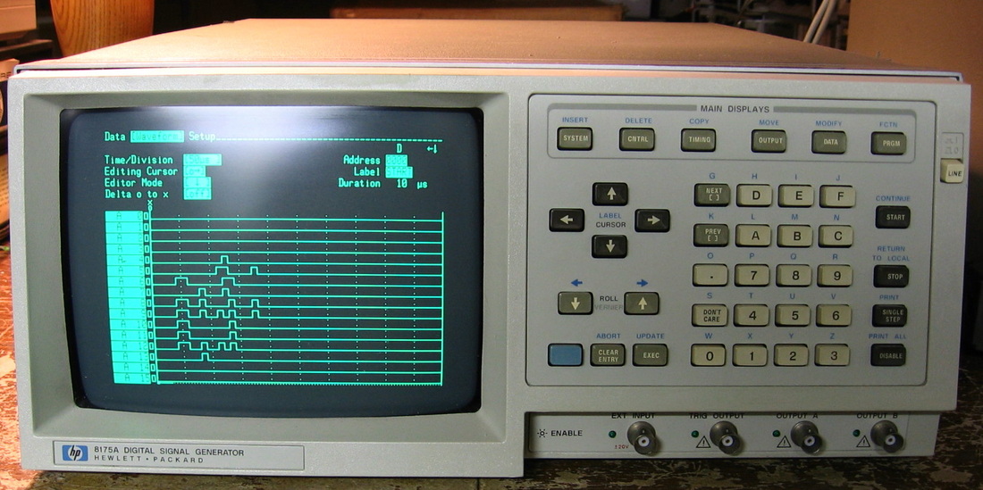
HP 8175A: Digital Signal Generator, 24-channel parallel, 2-channel serial. Also has Option 002 - analog arbitrary waveform generator. The matching stimulus unit to the HP 1630G logic analyzer. Somewhat cumbersome to use. (PDF) Grade: B+
There is an expensive option to the HP 8175A that adds two channels of arbitrary analog waveform generation. At first, nothing came out of the two analog output ports, so I just figured the option wasn't installed (it wasn't advertised by the eBay seller as having the option). But after I dissected the unit, I saw the waveform generator board (it was pretty well hidden beneath the motherboard) and then discovered that whoever installed the board forgot to hook up any of the cables coming off of it. D'oh.
Postsciprt: Preemptively replaced the Rifa 0.022 uF Y-capacitor in the power supply with non-Rifa 0.01 uF Y-capacitor.
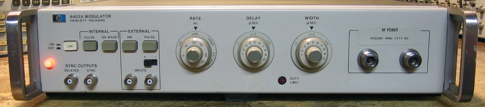
HP 8403A: Modulator, configured for 0.8 - 2.4 GHz. This is a curious piece that was manufactured for 20 years starting in the mid-1960s. At that time, HP realized that PIN diodes could be used to make a current controlled absorptive attenuator. They produced the HP 8730 series of modulators in various ranges up to 12.4 GHz. Just pipe your CW signal generator through one of these and you can have pulse or AM modulated signals coming out. Of course, you still had to supply the correct V and I to control these PIN diodes; the control signal has to have the correct shape however (not just a simple pulse). So HP designed the 8403A which internally generates control signals for pulse and square wave modulation (to about 50 kHz) and also accepts external pulse and AM modulation sources (to 500 kHz (FM) and 10 MHz (AM)) to once again generate the requisite control signals. In a bare 8403A, the output control signal was brought out to a front panel BNC jack along with a second BNC jack that was a basic general purpose pulse output. You had to manually connect the control signal output to your 8730 modulator. But somewhere along the line, HP decided to embed the 8730 modulators inside the 8403A as an option. Thus the two front panel BNC jacks were replaced by the input and output jacks of the PIN diode modulator block; the control signal output jack was eliminated (it is connected internally) and the general purpose pulse output BNC jack moved to the back panel. My unit contains the HP 8731B modulator rated from 0.8 to 2.4 GHz. In typical HP fashion, it operates outside these ranges for quite a bit. Nowadays, most decent signal generators have their own internal pulse, FM, AM modulation sources, so this unit is a bit of a dinosaur. (PDF) Grade: B+
The seller offered no real description of the condition of the unit other than it powered up (the neon bulb on the front panel lit). I don't blame him because to test this puppy, you need a microwave signal generator and a microwave spectrum analyzer. So for $40, why not? When I pulled it out of the box, there was a huge rattle coming from inside. I opened it up and found the BNC cable to the back panel disconnected and flapping in the breeze. Everything else looked pristine, but I noticed a Rifa 0.1 uF class-X suppression capacitor across the line filter, so this was immediately replaced with a 0.22 uF out of my junkbox. Even though there were no cracks in the Rifa cap, I know it is only a matter of time before it blows. I fired the unit up and it seems to work perfectly fine. I did notice that one of the front panel rotary switches was very loose, so that was tightened down. And there is a 12V bulb that lights when an illegal combination of rate, delay and width settings is selected. The bulb was intermittent - touching it with your finger seemed to make it go on and off. The bulb is in a metal housing with one power lead emanating out the back. The other power line is ground and HP relied on the metal housing of the bulb to make good contact with the front panel. But the front panel is painted, so they relied on a lockwasher to bite into it. However, the lockwasher doesn't make good contact with the bulb's metal housing. I don't know if this was the original condition or a previous owner fooled around with it, but if it was the original, it is a huge design flaw in my opinion. Rather than screw around with various pieces of hardware, I simply removed the bulb and replaced it with an LED. The LED is a better solution anyway since it will last indefinitely.
The seller offered no real description of the condition of the unit other than it powered up (the neon bulb on the front panel lit). I don't blame him because to test this puppy, you need a microwave signal generator and a microwave spectrum analyzer. So for $40, why not? When I pulled it out of the box, there was a huge rattle coming from inside. I opened it up and found the BNC cable to the back panel disconnected and flapping in the breeze. Everything else looked pristine, but I noticed a Rifa 0.1 uF class-X suppression capacitor across the line filter, so this was immediately replaced with a 0.22 uF out of my junkbox. Even though there were no cracks in the Rifa cap, I know it is only a matter of time before it blows. I fired the unit up and it seems to work perfectly fine. I did notice that one of the front panel rotary switches was very loose, so that was tightened down. And there is a 12V bulb that lights when an illegal combination of rate, delay and width settings is selected. The bulb was intermittent - touching it with your finger seemed to make it go on and off. The bulb is in a metal housing with one power lead emanating out the back. The other power line is ground and HP relied on the metal housing of the bulb to make good contact with the front panel. But the front panel is painted, so they relied on a lockwasher to bite into it. However, the lockwasher doesn't make good contact with the bulb's metal housing. I don't know if this was the original condition or a previous owner fooled around with it, but if it was the original, it is a huge design flaw in my opinion. Rather than screw around with various pieces of hardware, I simply removed the bulb and replaced it with an LED. The LED is a better solution anyway since it will last indefinitely.
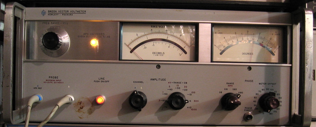
HP 8405A: Vector voltmeter that measures amplitude and phase between two channels. Uses similar probes to the HP 3406A. Good to 1 GHz. Not too much to be said - a basic RF instrument. (PDF) Grade: B+
As with a lot of HP pieces of this vintage, replacing electrolytic capacitors is the order of the day.
As with a lot of HP pieces of this vintage, replacing electrolytic capacitors is the order of the day.
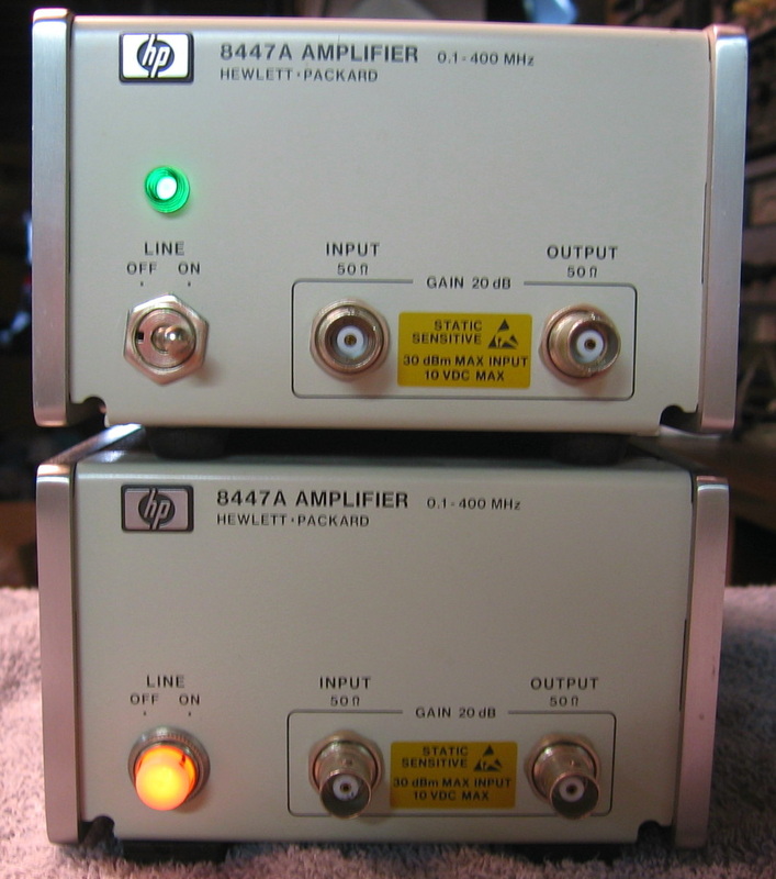
HP 8447A: The 8447A is a very simple 0.1-400 MHz 20 dB RF amplifier, plain and simple. Take a $40 minicircuits amplifier, a $25 HP power supply, and sell it for $1,500. That's the HP way. The top unit required a little rework to the power switch. The specs say 400 MHz, but it easily goes above 700 MHz. (OM) Grade: B
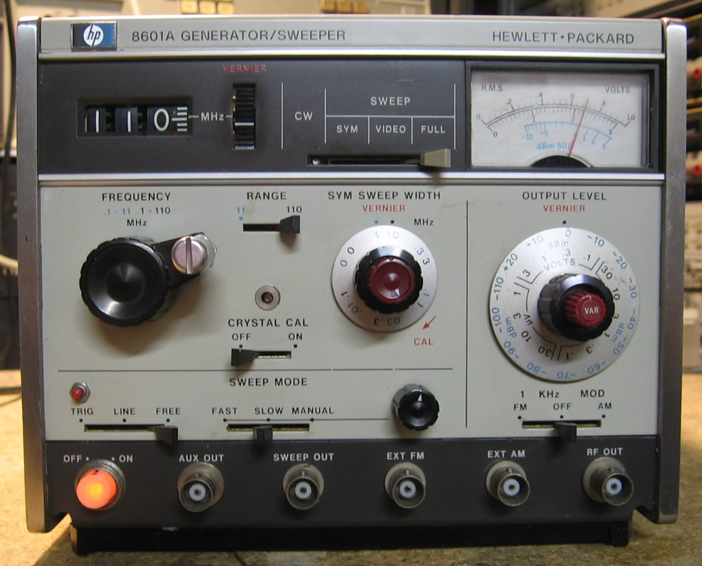
HP 8601A: 110 MHz Sweeper. This is a curious piece that operates both as a CW signal generator and a sweeper. It functions in two bands, 0.1 - 11 MHz and 1 - 110 MHz. There are three types of sweeps: 1) symmetrical, which generates sweeps around the dialed-in center frequency (sweep widths selectable on front panel); 2) video, which generates sweeps from the bottom of the band up to the dialed-in frequency; and 3) full, which generates sweeps across the full band, regardless of the dialed-in frequency. The sweep speeds are controlled by knobs/switches on the front panel and one can also operate the sweep manually via a knob. As an RF signal generator, the 8601A is not for precision work. The numerical frequency readout is only approximate, and the stability and drift have poor specifications. The amplitude, however, goes from about +18 dBm to less than -120 dBm and I measured the error to be less than 0.5 dB everywhere. The 8601A has rudimentary modulation capabilities and will do a fixed 30% AM and a fixed 75 kHz deviation FM (7.5 kHz on the 0 - 11 MHz band). There are provisions for external modulation, but that only extends the modulation capabilities slightly. It also has a 5 MHz crystal calibrator that I have yet to learn how to use. The chief utility of the 8601A is the sweeping, however. With most of my RF synthesizers, any sweeping is slow and jumps in discrete steps. With the 8601A, it is perfectly smooth. I've found this piece quite useful in verifying the bandwidths of many of my broadband AC voltmeters, for instance (PDF) Grade: A-
This piece was another in a long series of advertised as not powering on. The unit contains several custom HP hybrid amplifiers and the forums are full of people searching for an equivalent replacement. But I thought I would take a chance on it, even though it was being offered by a test equipment dealer who ought to know about these things. So I expected the power supply would need to be repaired. But no, the unit didn't power on because the power switch was dirty. I removed the lamp/cover from the switch, sprayed in contact cleaner, exercised the switch a few times, put back the lamp/cover and the thing powered up fine. It also worked fine. Cosmetically, it was missing the amplitude vernier knob which I replaced with an old Tektronix red knob and the main tuning knob's spinner was missing. I took a screw, a long spacer, a nut and epoxied it into what was left of the hole the spinner attached to. Good enough for government work.
This piece was another in a long series of advertised as not powering on. The unit contains several custom HP hybrid amplifiers and the forums are full of people searching for an equivalent replacement. But I thought I would take a chance on it, even though it was being offered by a test equipment dealer who ought to know about these things. So I expected the power supply would need to be repaired. But no, the unit didn't power on because the power switch was dirty. I removed the lamp/cover from the switch, sprayed in contact cleaner, exercised the switch a few times, put back the lamp/cover and the thing powered up fine. It also worked fine. Cosmetically, it was missing the amplitude vernier knob which I replaced with an old Tektronix red knob and the main tuning knob's spinner was missing. I took a screw, a long spacer, a nut and epoxied it into what was left of the hole the spinner attached to. Good enough for government work.
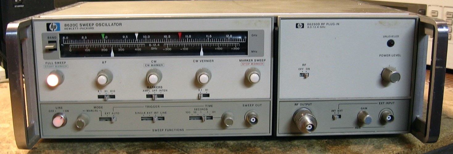
HP 8620C/86250D: The 8620C is a microwave sweeper mainframe and my unit is populated with the 86250D plug-in which goes from 8.0 to 12.4 GHz with a maximum power output of about 15 dBm. The mainframe is kind of cute with separate tuning knobs to control the sweep excursion. One can also, of course, run it in CW mode, although the frequency drift over time is not very good (mostly a function of the plug-in). Functionally, there isn't much to this piece - a ramp generator in the mainframe and a YIG oscillator in the plug-in. My plug-in has the ALC option (001) which HP eventually figured out was kind of necessary and thus made it standard in later versions. I would rather have a different plug-in, like the 2 - 18 GHz one, and plug-ins are plentiful on eBay. However, you need the associated dial marking piece that goes in the plug-in and these, of course, are nowhere to be found. I suppose you could print one out on the computer though. Not as good as a full fledged microwave signal generator, like my Gigatronics 900, but kind of cute nonetheless. (PDF) Grade: A-
This piece was advertised as not powering on and with knobs that were difficult to turn. The seller was completely right and a few squirts of WD-40 freed up all the tuning knobs. I was getting infinite resistance across the hot/neutral of the AC receptacle with the power switch on, so that meant the switch was no good. But a few squirts of contact cleaner into the switch brought it back to life. Everything checked out electrically and I was about to claim victory when I noticed that the sweep time vernier pot control was missing. Actually, the shaft of the pot had been sheared off flush with the front panel. It was such a clean break that it didn't even catch my attention. I replaced the pot and put on a knob and all is well.
This piece was advertised as not powering on and with knobs that were difficult to turn. The seller was completely right and a few squirts of WD-40 freed up all the tuning knobs. I was getting infinite resistance across the hot/neutral of the AC receptacle with the power switch on, so that meant the switch was no good. But a few squirts of contact cleaner into the switch brought it back to life. Everything checked out electrically and I was about to claim victory when I noticed that the sweep time vernier pot control was missing. Actually, the shaft of the pot had been sheared off flush with the front panel. It was such a clean break that it didn't even catch my attention. I replaced the pot and put on a knob and all is well.
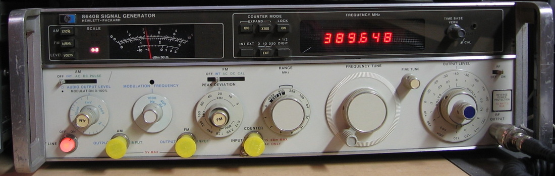
HP 8640B: The ultimate in analog signal generation. Uses a mechanical cavity tuned oscillator and achieves phase noise specs that are outstanding. AM and FM modulation. HP must have sold tens of thousands of these over the years. Every lab seems to have one. (PDF) Grade: A-
This was one of the first signal generators I worked on. When I first turned it on, the P/S caught fire - literally. After I put the fire out, there were a few traces that had melted away. Jumpered them with heavy gauge wire. A couple of years later, the display intermittently showed the frequency as 0000.00. Turns out that they mounted the P/S pass transistors on the back panel and then put a metal screen over them. Metal screen gets pushed in, touches the TO-3 cans, shorts to ground, you get the picture.
Postscript: Preemptively replaced the Rifa 0.022 uF Y-capacitor hanging off the line filter with a non-Rifa 0.01 uF X-capacitor. The capacitor was across L-N, and the line filter internally had two Y-capacitors between L-G and N-G, so using an X-capacitor was fine.
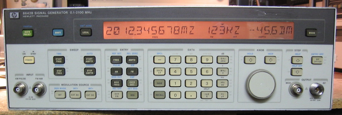
HP 8642B: High fidelity signal generator, 100 kHz to 2,115 MHz. The 8642A/B generators were designed as a "replacement" for the universal, but aging, HP 8640B (see entry above), which achieved excellent phase noise and spurious specs due to its cavity tuned oscillator. The 8642 series claims to beat the 8640's phase noise by 6 dB even though it is a digital synthesizer; it uses a surface acoustic wave resonator, whatever the hell that is. HP claimed it was the best signal generator on the market in the late 1980s, although their 8662A signal generator had slightly better phase noise at <5 kHz offsets. The 8642 phase noise spec is as low as -148 dBc/Hz at 20 kHz offsets and the spurs throughout the range are <-100 dBc. Amplitude ranges from +20 dBm to -140 dBm (a little lower maximum power at higher frequencies). Unlike many other (cheaper) generators, the modulation capabilities are excellent, providing AM, FM, pulse and phase (and combinations of these). A very nice internal low frequency oscillator offers continuously tunable modulation frequencies up to 100 kHz. This oscillator is spec-ed at a best-case distortion of -72 dBc, but I hooked it to my HP 8903A and it read an amazing -92 dBc, making it second only to my HP 239A oscillator in terms of distortion. The only negative thing I can say about the 8642 is the way it handles frequency sweeps. Normally, it has a discrete set of steps and, in combination with the relatively slow 85 msec switching time, tends to leave artifacts on the spectrum analyzer when viewing the sweep. Fortunately, HP also provided a phase continuous sweeping mode, although only over smaller ranges. If that's not clear, there are 18 pages in the op manual devoted to frequency sweep modes. This beast also has an extensive set of special functions and menus that I have only begun to play with. I call it a "beast" because it weighs 72 lbs - something like a total of 20 lbs of metal individually surround each of the major RF modules. At a mid-1990s price of $41,000, it ought to be outstanding - and it is. Deserves a solid grade of "A," but I'm going to deduct points because servicing and/or calibrating this piece is next to impossible (the manual is over 1,500 pages). For instance, each module is individually serial-numbered and has a matching set of cal constants that get transferred and stored on a little calibration EAROM board accessible through the back panel. And this is on top of the auto-calibration routines built into the instrument and the manual adjustments. Working on this is not for the faint of heart! And on such a high-end piece, you couldn't have made an OCXO standard HP? I mean, seriously, the stock oscillator is crap. And while I'm complaining, why does it take 30 seconds for this thing to boot up? Take a lesson from the Fluke 6080A. (OM) Grade: A-
Rather than enter the $1.5 billion Powerball lottery, where the odds are something like 1:239,000,000, I figured I'd spend $200 on the lottery for a $41,000 MSRP piece of HP gear, even though the seller advertised the piece as not starting up, but throwing errors A11 and A12 (PLL unlock errors). I conjectured maybe it was a power supply fault or he forgot to hook up the reference oscillator cable on the back panel (there was no listing photo of the back). Upon receipt, I turned it on, it went through its 35 second self-test and threw no errors at all. In fact, I can't find a single thing wrong with it. The only rationale I have is that I noticed the seller had two of these for sale and the first one sold about 5 months earlier. I got the second one and perhaps he never even tried that unit. The one I got didn't match the listing photo (the picture must have been the first unit). And the chances that two units had exactly the same errors seems kind of low (but not as low as 1:239,000,000). All OK with me as one look inside would be enough to convince you that repair is probably futile.
Postscript: I added a Vectron OCXO powered off the unregulated 8 VDC through an LM317 to 5V. This was placed externally on the back panel and routed into the external oscillator input jack. It was just too cumbersome to attempt to place the OCXO within the unit.
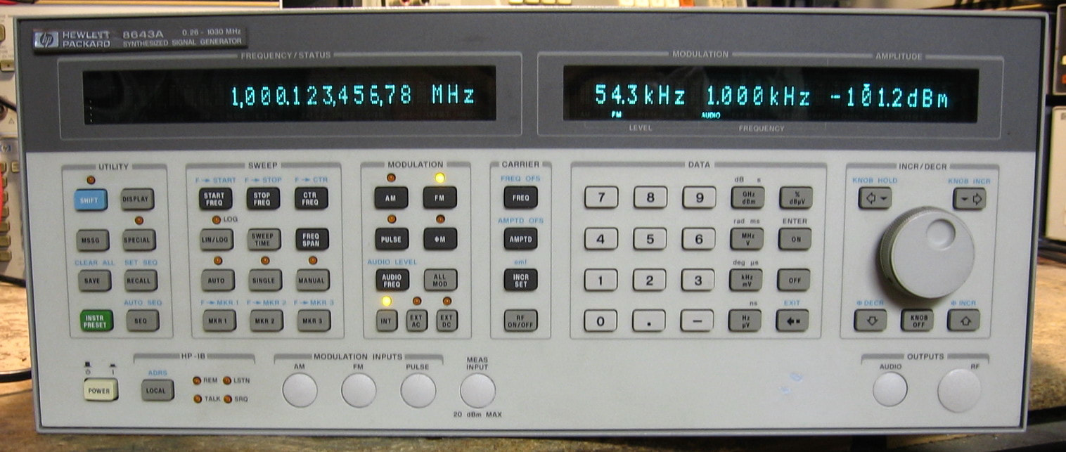
HP 8643A: 0.252 to 1030 MHz high fidelity signal generator. HP made a few of these "High Performance" RF generators, such as the 8643A, 8644A/B, 8645A, 8664A and 8665A/B, which are all basically the same fundamental unit. My 8643A is the lowest performance unit of the bunch. For instance, the difference between my 8643A and the 8644A is that my unit uses a switching power supply whereas the lower phase noise 8644A uses a linear supply. Contrast these signal generators to my HP 8657A which HP listed in their catalog as "Economy". The 8643A is certainly more capable than the 8657A, but not quite as good as my 8642B (although I like the 8643A better than the 8642B). As with most HP signal generators, the specs are excellent and this 50 pound beast is built like a tank. Well, that is, a tank with a cheap power supply. For some reason, HP purchased a COTS switching power supply, model nfs96-7630, from Computer Products (later Artesyn). I guess it was so noisy that HP added their own filter/regulator board after the power supply. But the switching power supply is extremely cheaply designed and manufactured. It rivals even the bottom end of cheap Chinese PC power supplies you can buy for $25. I don't fault HP for not wanting to design their own power supply, but you would think for a signal generator that costs nearly $20,000, HP would have at least sourced a decent one. My unit has Option 003 (rear panel connectors which I despise) and Option 011 (an internal 2 GHz frequency counter). There are all kinds of special functions including many to control the multiple independent internal audio modulation waveforms. In fact, the audio subsystem is reportedly based upon the same ASIC used in the HP 8904A multi-function synthesizer and some users have commented that they use the 8643A as a very capable audio function generator. All in all, about as good as you can get. (PDF) Grade: A-
*** SPECIAL NOTE *** This piece is #402 of my collection and has the distinction of vaulting me past the $2,000,000 mark for original MSRP (not that the MSRP means anything today, but it is fun to keep track).
I bought this 8643A for $95 + $30 shipping, an excellent price. It was advertised by someone who claimed it was a working unit when he purchased it, but did not power on when he received it. When I received it, nothing happened when I pressed the power button, but I could see that about 40 watts were being drawn off the AC line, so something was at least starting. Two of the eight P/S valid LEDs were lit and those were due to the auxiliary switching power supply (a separate unit) supplying power to the OCXO and some other things. But all of the voltages (5, -5, 15, -15, 10, 38) out of the primary supply were near zero. I pulled out the main power supply and separated the COTS switching supply from the HP filter/regulator board. Set up a test jig on the bench and fired it up. Nothing was coming out of the supply (5, 15, -15, 38) and I noticed that after about 15 seconds, the switching transistor was already >150 degF. By looking at resistances, I found a shorted flyback diode on the secondary. It was rated as an 8A, ultra-fast switching diode, and I figured there would be something suitable in my collection of old, junk PC power supplies. And so there was, and in it went. That got the 5, 15 and 38 volt outputs up and running. But the -15 volt output was sitting at about -10 V and very slowly drifting towards -15 V (the furthest it got was about -12.5 V). Looked like some sort of capacitor was charging up. So I started pulling the electrolytic capacitors on the secondary and found several with puddles of leaking electrolyte. I pulled them all out, cleaned the board thoroughly, and replaced those that I had in the junkbox. Fired up the supply and my -15 V was restored. Put everything back into the 8643A and the unit powered up nicely. It threw a few errors mainly due to the RAM backup battery being dead. I replaced the 3.6V NiCd with two alkaline AAs with a series diode to prevent charging and went through the self-test and calibration. I did notice that when I invoked the Option 011 counter, sometimes the frequency display would blank randomly. And a few times, the self-test did identify a hardware error with the counter. I pulled the counter board out, cleaned it, reseated everything, and at least I haven't seen the counter malfunction again. However, I did notice that every time I turned the unit on, I would get a "hardware failure 18" message which says a failure of the counter. The user manual suggests that you run Special Function 171 which clears the RAM and does a recalibration. After I did that, I haven't seen the error message in several power-up cycles. I will have to watch it and see if the error comes back. Meanwhile, I can see nothing wrong with how the counter operates. Finally, when received, the front panel was a mess. It looked like this unit sat for several years in a dirty garage. However, it did clean up nicely as the photo shows.
Postscript: I hate rear panel connectors because almost all of my pieces are up against a wall, meaning I have to leave a BNC cable permanently hooked up and bring the cable out around the side of the unit to the front. So I was happy to see a very clean front panel
assembly being offered for $35 that had all of the front panel connectors and cables. It also had the complete keyboard and display assemblies which means I now have a spare for those. When received, everything looked in order and the front panel swap looked fairly straightforward. But then I noticed that the seller had simply attached an SMA cable to the rear of the RF Output N-connector on the front panel. This is not the correct cable which normally terminates into the attenuator board using a compression fitting. But not a problem, I simply took the cable out of my unit that was going to the rear panel N-connector. It was too long, but I just bent it gently into a loop so that it would fit. I left the Option 11 counter input jack on the rear panel for a couple of reasons: 1) the rear panel BNC jack was not the right type for the new front panel, and 2) I won't be using this Option very much (or at all). The whole operation took about three hours since I had to do a lot of disassembly to get to the connections on the rear panel. Also, I used the display that came with the new front panel, which, unfortunately, isn't as bright as the old display. I'll leave it that way until the vacuum fluorescent displays die. Then I will simply put in the other display board from the original front panel.
Postscript^2: Once I figured out that I could get the front panel off and exchange the display board with minimal disassembly, it was a simple matter to put the brighter display in. Took about 20 minutes and now I am happy.
Postscript^3: One day, I turned the 8643A on and it went into calibration mode. This normally means a bad RAM backup battery, but the battery voltage (2 AA batteries with a series Schottky diode) measured 2.92V which should be fine for the RAM. But then I measured the P/S voltages and found the 15V supply at about 14.2V, slowly ramping up to about 14.7V after a few hours. This led me on a multiple day digression into the P/S. I found nothing overtly wrong with the supply and the voltage drop seems simply due to the resistance in the wires leading from the supply to the boards (the unit draws >3.5A at 15V). The unit would be fine (meaning normal startup with no calibration) on several attempts during the day, but let it sit overnight and the next morning it would go back into calibration mode). I removed my 2 AA batteries, which were in a cheap plastic holder with a switch, and replaced them with 3 AAA batteries and a normal diode - I'm getting now about 4V at the RAM. It has now started up fine without cal on two successive mornings. Could have been bad contacts/switch in the cheap battery holder, or a marginal connection from the uP board to the motherboard (the battery voltage leaves the uP board, goes through the motherboard, and then back to the uP board), a marginal capacitor somewhere, or still something wrong with the P/S. I found a replacement P/S (all three boards) for $35 on eBay, so I have ordered that just in case. Until something becomes obvious, it remains a mystery. Indeed, the uP does measure the battery voltage, but my series diode prevents it from actually seeing the battery, thus the test should always pass (5V is applied to the measurement point when the unit is powered up). Meanwhile, even when the unit goes into cal mode upon startup, it passes the self-test and works flawlessly. Oh, and while I had the P/S out on the bench, I replaced the two Rifa caps, one of which looked like it would explode pretty soon.
Postscript^4: All of the previous discussion on a bad back-up battery was a red herring I think. The thing went back into the mode where it starts to calibrate upon startup. And it finally threw a "14.040.xxx" error code which is a low 15V rail. All the while, the RAM saved my previously stored configuration data. So that led me back to my initial problem with the power supply. I managed to buy a replacement for all three P/S boards for $35 on eBay (advertised as probably working). But the smaller (24V) supply had a blown flyback diode and zero output voltage. I replaced the diode, re-capped both COTS switching supplies just to be sure (with Nichicon 105 deg low impedance caps) and stuck them in the 8643A. With the old P/S, I was getting 15.03 V with no load, but when connected to the unit, the P/S started at about 14.2 to 14.3V and slowly ramped up to a high of about 14.7V. With the new supply, the no load voltage was 14.92, but when connected, the voltage started at 14.78 and within a few seconds ramped up to 14.83V where it moved 0.7mV over two hours! Much, much better. We will see if this finally cures the startup calibration. I'm still not sure what happened since the old supply seemed to work OK on the bench while connected to one of my dynamic load units, and any voltage drop seemed to be coming from the connectors/wires. Perhaps all this jostling of the connectors finally broke the dirt free, or stressed a marginal solder joint on the connector.
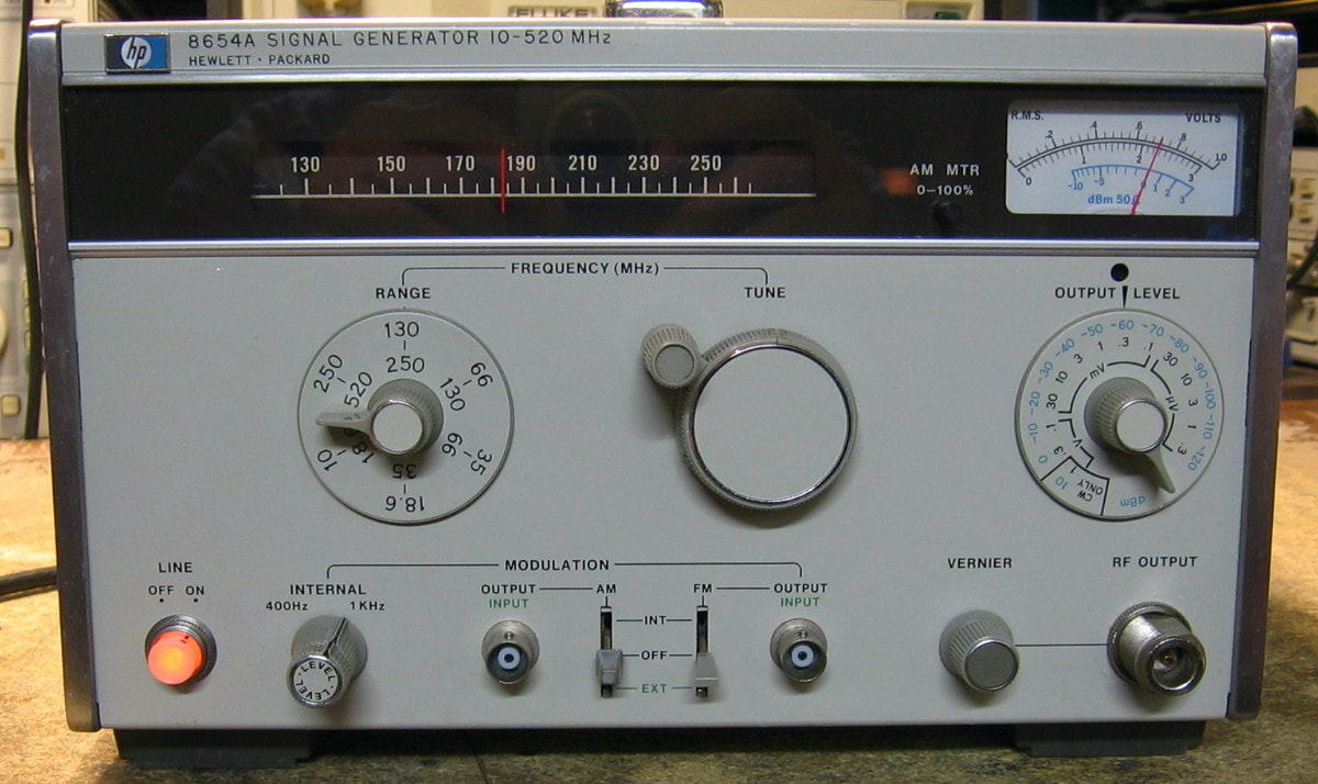
HP 8654A: Low cost, portable signal generator, 10 - 520 MHz, +10 to -130 dBm. The 8654A was introduced by HP in 1972 as the first transistorized substitute to the HP 608, with performance approaching the venerable HP 8640A (introduced one year later). It is a basic generator whose frequency obviously cannot be set with any accuracy (specification is +/-3% after a 2 hour warmup) and whose drift is specified as 1 kHz in 5 minutes (although mine is certainly a lot better). Harmonics are woefully inadequate at only -20 dBc (again, mine is
more like -40 dBc). The step attenuator inside is as good as any modern unit, so the amplitude accuracy is fine. It will do AM or FM modulation (400Hz/1kHz internally, or externally supplied), but once again, I wouldn't trust the meter to give you a very accurate prediction of the levels set on the front panel level control. The build quality is curious: there is one exposed circuit board, but the entire RF generation circuitry is in a heavy die-cast box with access ports to adjustments obtained by unscrewing various round covers. Inside the RF box is a variable capacitor and a set of inductors that are on a turret and are rotated around by the band select knob. Heaven help you if you need to fix something inside the box. The one thing going for the 8654A are the "physical" specs, 17 lbs, 10 watts, 7" x 10.5" x 12", making it a nice piece to move around the lab where needed. (PDF) Grade: B+
I picked this piece up for $75 shipped in condition unknown. It had calibration seals intact and a sticker from 1984, so I guess it hasn't been opened up in 35 years. Everything seemed to work fine except for a dirty modulation level pot. If I could get the pot out, there's a chance I could dissect it and spray in some cleaner. But the best solution would be to replace the pot. And I might have a chance if I could get the front panel off. But this requires removing the modulation frequency knob whose Allen screws are stripped. Oh well, a project for another day.
HP Pozidriv Bonus Rant: I have worked on probably over 100 HP pieces and in almost all cases have simply ignored the Service Manual's warnings saying that the piece uses Pozidriv screws, not regular Phillips-head. I have been using Phillips bits in my electric screwdriver for years noting that when the torque clutch disengages, the bit is usually skipping out of the screw head. But I stumbled upon a nice set of Wiha Pozidriv #1, #2 and #3 bits on Amazon for $12, so why not? (Actually, after I bought them, I found the same set on eBay for $9). The 8654A above was the first unit that I tried the Pozidriv bits on. What a difference - it's almost like the bits were made for the screws!!! Made a believer out of me.
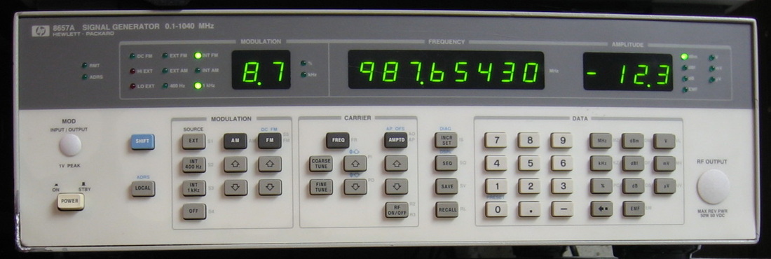
HP 8657A: Highly popular $10K synthesizer, good to 1 GHz, -140 dBm. Nowhere near the purity of the HP 8640B, but certainly easy to use. Would be easier to use if it didn't have the rear panel output jack option. (PDF) Grade: A-
I love this one! It was advertised as "doesn't power up." Just what I like! I turned it on - and nothing. Well, almost nothing. I did see one LED flash. Well, at least the LED got power. Then I looked at the back panel and saw the 110/220V switch set to 220V. From now on, that's the first thing I check. Now that it powered up, it still didn't work. I didn't yet have the manual, so I opened it up. I found five wires coming off a harness going to one of the main boards. All five were floating in mid-air. Now where do they go? Luckily, I found a picture of the insides of an HP 8657A on someone's web site. Used the picture to connect the wires. Works like a champ
Postscript: After many years, I got tired of the rear-panel output option and so mounted an N-connector on the front panel and re-plumbed the insides. Now I don't have to waste a 6' BNC cable getting the signal from the back of the unit.
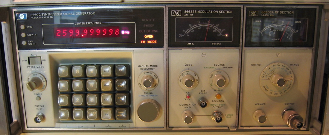
HP 8660C: Synthesized Signal Generator configured to 1300 MHz. The HP 8660C is the mainframe and mine is configured with the HP 86632B AM/FM modulation generator and HP 86602B RF section. Amplitude is controlled by both a step attenuator and vernier pot and ranges from +10 to -136 dBm with a basic accuracy of about +/-2 dB. FM deviation goes to 1 MHz in three ranges. The unit has a moderate amount of sweep capability and also has a real front panel tuning knob, something many HP generators lack. The frequency resolution is 1 Hz and there is an ovenized oscillator which takes about 20 minutes to warm up unfortunately. The phase noise is about -105 dBc at 10 kHz, which is OK. I certainly can't see the difference between the 8660C and the HP 8657A on my Rigol DSA-815 spectrum analyzer (and that's probably because the analyzer's phase noise is much worse than both generators). My only complaint is the strange man-machine interface. If I want to generate a signal at 456 MHz, I punch in 4, 5, 6, MHz and CF on the front panel. OK, but while I'm doing that, I see absolutely no change on the display. The keyboard entries go into a buffer and aren't made available to the main display until the last button is pressed. Same deal for sweep width and frequency step. But, see the three little buttons in the top left corner? They hold the register contents as you are typing them in. So if you hold in a button, you can see what you enter. But the main display? Forget about it. Very strange. And not particularly obvious if you are trying to fix a broken one and can't figure out why no key press shows up on the display! The basic control is a state machine and they give you LEDs and a single step button so you can follow the program as it moves along. (PDF/OM) Grade: A-
Postscript: Spent a little more money and recently upgraded to the HP 86603A RF plug-in. That now gives me frequencies up to 2.6 GHz, but with relaxed specs compared to the 1.3 GHz HP 86602B. I also got a good deal on another HP 86632B modulation plug-in which allowed me to replace the sticky meter in mine (see the repair notes below). As now configured, this beast sold for more than $30,000 in its last years at HP. Good grief!
Bought this advertised as keyboard not responsive. But it truly was broken, not just an artifact of the keyboard/display action as described above. A fair amount of digital debug isolated the problem to one (or possibly two) boards, and I was pretty sure that one or more of the nine 74150 multiplexers on one board was faulty. This prevented the state machine from correctly obtaining the various data pieces and hung the machine up. Rather than scrounge around for a bunch of ICs, the simplest thing to do was spend another $75 and buy a parts mule for the 8660C mainframe that was advertised as working, but the OCXO was subsequently ripped out. Meanwhile, the main bridge rectifier for the 5V supply opened up on one half and I was getting a lot of ripple. Also, the attenuation knob on the 86602B was dirty and made the step attenuator's relays gyrate like crazy. A shot of cleaner fixed that. When the parts unit arrived, I replaced a few boards and the rectifier. Problems mostly solved, but the meter on the 86632B modulation plug-in was frozen. I dissected the meter only to find the entire magnetic torus surrounding the movement was filled up with tiny metal slivers. It took a long time to remove them all (they are magnetic after all and like to stick), but the meter movement is now mostly cured (a small tendency to stick at full scale).

HP 8672A: Microwave synthesized signal generator, 2 - 18 GHz. Sold for over $40,000 in its later years, this is a very nice synthesizer that uses a YIG oscillator running at 2 - 6 GHz, followed by a YIG multiplier that either doubles or triples that baseband. Does AM and FM modulation as long as you supply the modulating signal to the front panel jacks. However, the FM deviation is restricted to a maximum of about 5x the modulating frequency, so you can't, for instance, use a 1 kHz sinewave input to the front panel and select 300 kHz FM deviation. Most of my other signal generators are much less restrictive. Nominally, the 8672A will output 0 dBm maximum, but my unit has Option 008 which boosts the output power to +8 dBm (or higher). In later years, HP abandoned this option and simply included it in all 8672As. The thing is built with typical HP-overengineering of the 1980s with about 25 PCBs and a slew of microwave modules, yielding a unit that weighs 60 lbs. The only bad thing is the lack of readable service manuals online. HP made the 8672 (and the junior version 8671) for so long, there are about six different manual versions - only one of them has readable schematics and, of course, it isn't the one I need. Shown in the photo with the RF turned off so that it lit up a few more of the front panel lights. (PDF) Grade: A-
Bought this for $80, which is a very good price. It was advertised as "no output," and the front panel indicator lights showed "out of range." The photo also showed several of the indicators that should have been lit were dark and the frequency digits were flickering. When received, I turned it on and the "out of range" light had extinguished, but the "not phase locked" light was lit. The frequency readout was stable at 3000.000 MHz, exactly where it was supposed to be. When I hooked it up to a spectrum analyzer, I did get a signal near 3 GHz, but it was pretty jittery (as one would expect if it wasn't locked). Moreover, when I tuned the frequency dial, sometimes the signal moved to the correct frequency, sometimes it stayed where it was, and sometimes the frequency went in the opposite direction to my tuning change. Yes, there is a technical term for this behavior: "broken!" When I removed the top cover, I saw a handwritten noted taped to one of the module covers dated 2000 (19 years ago). It said that 1) the YIG multiplier power drops below 8 dBm when warmed up, and 2) replace bad A3A6 (YIG oscillator driver) board. So I went to the A3A6 diagnostics in the service manual and the board seemed to pass the tests. I noticed on one of the digital boards there were 4 LEDs, three of which were lit. Turns out that there are 4 (interrelated) PLLs in this beast and those 4 LEDs are the lock indicators. The unlit LED was the VCO PLL - this would make sense if the note about a bad A3A6 board was really true. Well, there are a bunch of pots on A3A6, and it is a general rule of test equipment repair that one must always turn every pot (just to see what it does). After turning a few, the VCO PLL LED lit up, the front panel "not phase locked" light extinguished, and the output at 3 GHz was perfectly stable.
Or so I thought, because when I turned the frequency knob, the low frequency PLL LED lit up and the thing was either 1) spot on the tuned frequency, 2) exactly 8 MHz low, or 3) completely random (with the VCO LED lit up again). The low frequency stuff is contained in a set of three boards in a sealed aluminum case. Which I guess is good, because it saved the leaking juice from the three NiCd batteries, which are mounted on the outside of the aluminum case, from completely soaking the boards. Some juice had seeped inside the case, but the three boards looked like the previous owner had cleaned it all up. The diagnostic tests on the boards failed, but I attributed the failure to the fact that at the test frequencies, the VCO PLL was also not locked.
At this point, it almost looked like a digital problem - the correct frequency was not being read from the front panel frequency encoder. I removed the state-machine board and reseated it. At this point, the frequency digits were completely scrambled and nothing worked. Giving the board a little nudge with a hammer seemed to restore it back to where I started from. But then I noticed that if I also hit the board with the four PLL LEDs, the LEDs would blink on and off. So I removed, cleaned, and reinserted that board. Much to my surprise, all four PLL LEDs lit and things started to look reasonable. Except, since I had turned the pots on the YIG driver board, I had to go back and readjust those.
While I was in there, I removed the NiCd pack and put in a new holder and three new batteries. I still had to deal with several burned out bulbs in the front panel, but things were starting to look good. I let everything warm up, and as the note said, the max power dropped from about 10 dBm to 0 dBm in "band 3", 12-18 GHz. That seemed kind of strange, since the YIG multiplier worked fine in "band 2", 6-12 GHz. All the YIG multiplier does is use a step-recovery diode to generate harmonics and then a filter to select the proper harmonic. Doesn't sound like a temperature-related thing to me only in one band. So I went to the YIG multiplier driver and turned about 3 pots 15 degrees. The power instantly went up to 10 dBm across 12-18 GHz.
I was ready to claim victory when I noticed that the output was now suddenly 20 dB too low. After checking the step attenuator driver board, it became clear that the 20 dB pad in the attenuator was stuck on. I removed the attenuator and proceeded with the dissection. HP's design uses spring contacts that interrupt the voltage to the solenoids so that they do not continue to draw current after switching. Sure enough, the 20 dB pad's contacts were dirty, and after a gentle cleaning, the 20 dB pad properly switched on and off. Unfortunately, a day later, the 40 dB pad acted up in the same way. So out came the attenuator again and this time I cleaned all eight contacts. Hopefully this will last. If not, I can do a better job cleaning them once I get a jeweler's file and/or some miniature watchmaking tools.
Finally, about 1/3 of the light bulbs were burned out in the front panel. I decided to replace all 28 bulbs, which wasn't cheap (~$35).
Postscript: Preemptively replaced the 0.1 uF Rifa X-capacitor hanging off the power receptacle with a 0.1 uF non-Rifa X-capacitor.
Postscript^2: One day I noticed that the front panel "unlocked" indicator came on around 6 GHz or so, depending on whether I was tuning from below or above. The diagnostic LEDs on the control board indicated it was the YIG tuned oscillator loop that was malfunctioning, not the other three PLLs in this beast. The fact that everything remained in lock at 99.9% of the frequency range led to my conclusion that the piece just needed a minor adjustment, not that there was a fault. Most likely, the YIG was being pre-tuned to right at the edge of the PLL capture range. I hadn't done the alignment when I first got the 8672A, so this all made sense. The way this thing works is that the digital frequency data goes through a DAC and the analog voltage is then used to pre-tune the YIG. There are two pots that adjust the voltage at the 2 and 6 GHz limit points. So I could either try and adjust the DAC (difficult procedure) or adjust the two pots (much easier). When I had the unit at 6 GHz and unlocked, I turned the high limit pot about 5 degrees. The diagnostic YIG LED lit up, the unlock LED on the front panel went dark, and all was well. While I was in there, I also cleaned the connection to one of the front panel light bulbs that had become intermittent.

HP 8683B: Microwave signal generator, 2.3 to 6.5 GHz. HP made several variants of these generators. There was the 8683 series in an A-variant which was designed for communications testing and the B-variant which had extensive pulse modulation capability designed for radar testing. They also made a similar 8684 model with higher frequencies and eventually also a slightly more capable D-variant. These generators were built in the mid 1980s and served as a bridge between the earlier klystron-based microwave signal generators and the microwave synthesizers that came later. The 8683B uses a cavity-based oscillator like the HP 8640B and thus have very good non-harmonic spurious outputs. The specs are OK, but of course look horrendous compared to your ordinary 0-1 GHz RF synthesizer; I simply don't have enough microwave experience to adequately judge them. For instance, the power goes from +9 to -130 dBm with an accuracy of +/-3 dB. The phase noise spec is <-72 dBc at 10 kHz offset and the drift is spec-ed at <100 kHz/hour after 60 minutes warm-up. The frequency is a 4 digit display with an accuracy of about 1%. It will do AM to 10 kHz, FM to 10 MHz with 5 MHz deviation and pulse modulation to 1 MHz. Mine also has Option 002, the reverse power protection. At the time, this piece was the result of a major amount of innovation. If you want a good read on how engineering should be done, consult the July, 1982 edition of the HP Journal which is devoted to this piece. On the other hand, they did take shortcuts. Obviously they cannot figure out the exact frequency the cavity is oscillating without an internal counter. So HP hung a precision potentiometer on the tuning mechanism as a crude shaft encoder. Similarly, the large level knob on the right mechanically turns a step attenuator through a series of gears. They figure out the attenuation with another potentiometer/encoder. On the whole, a very nice implementation, but I think the Gigatronics 900 has it solidly beat in most respects. ($CD) Grade: B+
Advertised as condition unknown, it seemed perfectly fine when I got it and passed its series of 30+ diagnostic tests. But eventually I found two problems. The first was that the external AM button's LED was burned out and the second was that the external AM didn't function. This turned out to be a coincidence and there was nothing wrong with the front panel button decoding. Tracing through the signal path led me to a sensitivity trimmer pot on the A7 board which was open. This pot adjusts the signal from the front panel external AM BNC jack into the modulation circuitry. No signal, no modulation. I also checked the other two similar trimmers on A7 and one was open and one was marginal. So I replaced all three trimmers and life was good. I will probably not try to fix the burned out LED because pulling the front panel looks like a real chore and there is the distinct possibility that even if I get the panel off, I will destroy the switch trying to get the button off (I've done this before). That means I have to heat-stake in a new switch which is always dicey. Besides, when you press the external AM button, the modulation display comes on, so its not likely you wouldn't notice that. The only other fault was a missing spinner post on the frequency knob. I pieced together a replacement from a screw, bushing and a couple of nuts. Doesn't look as good as the original, but works fine.
Postscript: Well, due to my obsessive compulsive disorder, you know I couldn't live with that burned out LED under the external AM button. Took me about two hours to remove the front panel, replace the LED and reassemble everything. I managed to lose a C-clip along the way and had to manufacturer my own. Anyway, all the LEDs now light properly. After all, I wouldn't want my total of 2,029 LEDs to fall one short (at the time of writing, this total reflects pieces 1 to 316).
Postscript^2: Preemptively replaced the 0.1 uF Rifa X-capacitor hanging off the power receptacle with 0.1 uF non-Rifa X-capacitor.
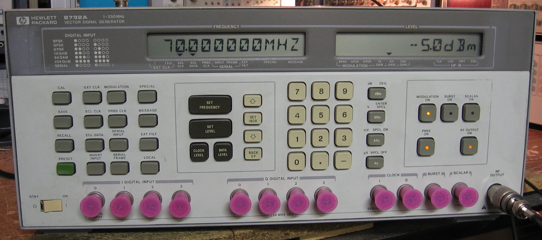
HP 8782A: Vector Signal Generator to 250 MHz. The problem with having pieces like the HP 8981A Vector Analyzer/Demodulator and the HP 3709B Constellation Analyzer is that I have nothing that will generate the necessary signals to exercise them. Well, not any more! The HP 8782A generates a variety of digital modulations (QPSK, 16QAM, 64QAM, 256QAM, BPSK, etc.) at data rates up to 100 MBaud and at carrier frequencies to 375 MHz (even though it is only rated to 250 MHz). As an RF signal generator with the modulation turned off, it is still a very nice piece, having an ovenized oscillator, very low phase noise, an accurate 110 dB step attenuator and a frequency resolution of 1 Hz. As you can see from the front panel, the operator can input digital I and Q streams, either serially or in parallel, in addition to the built-in PRBS digital random stream. Has loads of special functions that basically put impairments on the modulated output. Sold for $30,000 in the nineties and has as a 400+ page user's manual that you had better read carefully if you have any hope of using this piece to its full capability. On the other hand, the service manual is essentially worthless being of the HP 1990's design of "identify the faulty board and put in a new one." (PDF) Grade: A
I purchased this for $250 (ouch!) from an eBay "liquidator" seller, the kind that sells chain saws, sneakers, Barbie dolls and an occasional piece of test equipment. It was listed as "manufacturer refurbished." When it arrived, contrary to the listing picture, all of the BNC jacks had plastic caps, there was a fresh set of feet on the unit, and it had anti-tamper stickers over all the cabinet screws. Moreover, there was a label from a rather famous test equipment dealer as well as a sticker saying "performance verified July, 2014." In addition, the test equipment dealer's business card was attached as was his CD containing the operator manual. So I don't quite get it. This test equipment dealer sells new/used on his own web site, and also sells used equipment on his own eBay store. So why wasn't he selling it, rather than me purchasing it from a liquidator? Don't know - don't care. Anyway, there was a big sticker on the back that said 230V (why?), so I switched the unit over to 115V and turned it on. The self-test passed and all seemed well, but the RF level wouldn't go below -60 dBm. The step attenuator was clicking as I lowered the RF level to -70, -80, -90 dBm, but the spectrum analyzer showed the signal stuck at -60 dBm. Hit the CAL button, recycled power, and all is well. It may of been that the attenuator solenoids got a little stuck from a period of inactivity. But as you can see from the picture below, which shows the HP 8782A generating a 64 QAM signal as received/displayed on my HP 8981A Analyzer, life is good.
Postscript: Preemptively replaced the Rifa 0.1 uF X-capacitor behind the power jack with a non-Rifa 0.22 uF X-capacitor.

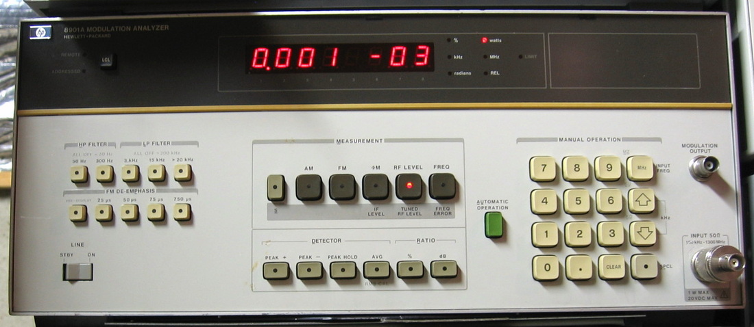
HP 8901A: HP's basic modulation analyzer. "One button" operation means that the user is pretty much out of the loop. Hook up a signal and watch. Even though there is a substantial set of "special" functions to set various internal parameters, you basically only get a couple of measurements and not a whole lot you can do about them. (PDF) Grade: B+
Preemptively replaced the Rifa 0.47 uF X-capacitor in the power supply with a non-Rifa 0.47 uF X-capacitor.
Preemptively replaced the Rifa 0.47 uF X-capacitor in the power supply with a non-Rifa 0.47 uF X-capacitor.
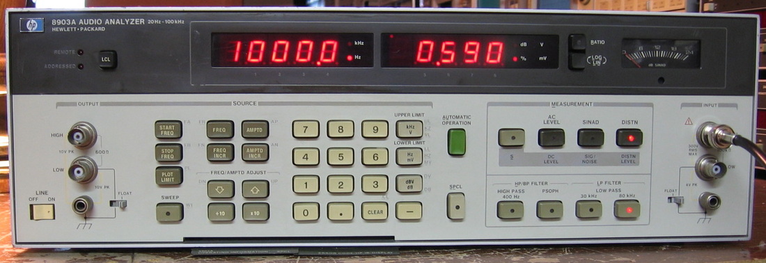
HP 8903A: Audio analyzer with extremely high fidelity signal source and measurements of AC, DC, distortion, SINAD, etc. Like the 8901A modulation analyzer, just hook things up and watch. Let's see, I can use the HP 334A, adjust a bunch of knobs, wait for it to null, and read the analog meter - or I can use the 8903A. Which would you choose? (PDF) Grade: A
This one took a while to fix even though it was simply A2C20. Was set to 220V, but I had learned my lesson from the HP 8657A (see that description).
Postscript: Although the 8903A can easily measure distortion to below -90 dBc, the calibration procedure that ultimately determines the measurement floor is controlled by a single-turn pot that is extremely difficult to adjust properly. I replaced the pot with a ten-turn version that is a little more forgiving.
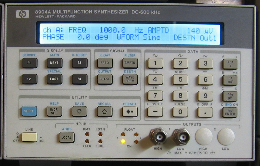
HP 8904A: Like the label says, a DC-600 kHz Multifunction Synthesizer. What they "forgot" to tell you was that only sine waves go up to 600 kHz; the rest of the waveforms only go up to 50 kHz. That's like advertising a car as getting 100 mpg and then finding out that's only in reverse. The basic no-frills version is ho-hum at best. But now that I've enabled Options 001/003/005, I get four independent waveform generators, which is a slight consolation. The sine wave distortion is -74 dBc at 1 kHz, so at least HP knew how to digitally synthesize that. Oh, and a few more gripes: 1) the S/N and Option codes are stored in volatile RAM (lose the battery and the unit is toast), 2) HP purchased the power supply, purchased the display and deemed the main board to be proprietary, so there is no service information provided, and 3) HP charged a ridiculous amount for software enabling the options that should have been included in the first place. But the most egregious fault is actually caused by the signal generation method itself. The thing basically repeatedly plays out a waveform memory and particularly with square and ramp waveforms, suffers from a +/-1 sample indecision at the boundary. Hence the waveforms jitter pretty substantially. Shame on you HP! (PDF) Grade: B
OK, follow me on this one. First, you need to know that the 8904A consists of four boards: 1) P/S, 2) display, 3) main board and 4) output board. A few years back, I had purchased an 8904A and upon receipt discovered that the internal battery had leaked all over the main board, pretty much destroying everything near it. Because no service information on the main board was provided by HP, I removed the P/S and display, gave the output board to a buddy of mine who put it in his 8904A as a second output channel, and threw the rest of it in the garbage. Now fast forward to the present, where an eBay seller was offering an 8904A with 1) no output board, 2) a messed up display with missing parts and 3) the usual "doesn't power up" description. So, for $35, it was worth a risk as I already had a replacement display, a replacement P/S, and my buddy gave me back the output board. When I received the new 8904A, the P/S did not turn on, and although I could have used my spare, it was pretty easy to find the faulty flyback diode and get the new P/S working. I took the missing display parts out of my spare and installed them. I took my output board and installed that next. When I turned it on, I got no output. I verified that the main board was functioning correctly, so that left the output board. My buddy swears it was working when he gave it back to me. I traced the defect to the sampler amplifier which consists of two 2N4416A N-channel JFETs in a cascode configuration. I will refer to these as the upper and lower transistors. The upper transistor is controlled by the output of an LH0002CN buffer and the lower transistor by an LF356 op-amp. Thus there are two interrelated feedback loops going on. The upper transistor tested bad so I placed an order with Mouser. When I put the new one in and turned on the 8904A, the two metal can pass transistors on the board's P/S blew (not before I burned a nice 1/8" hole in my finger touching one of them). I then noticed that the LH0002CN buffer tested 5 ohms from the rails to the output, so that had blown. I replaced the two pass transistors and ordered a new buffer chip from China. When I received that, I fully thought the 8904A would be fixed. But no, as soon as I turned it on, it popped the upper 2N4416A again and the LH0002CN got real hot. For a few days, I studied the schematic and simply could not figure out where the current was going, because the lower transistor was cutoff completely (-30V back biased gate). Finally, in desperation, I removed about 20 parts surrounding the circuit. Only when I was randomly checking things with an ohmmeter did I spot the problem: this board was also hit by the original leaking battery and managed to form a 100 ohm path from the junction of the upper and lower transistors to ground. I removed the corrosion and installed all new parts in the sampler amplifier. Now I have a working HP 8904A (finally). But just to keep things interesting, while I was calibrating the unit, I accidentally shorted a test point to ground and blew one of the output amplifier transistors and one of the P/S pass transistors (yet again).
Postscript: The original EL-LCD display on the 8904A is quite dim. And when the backlight shuts off automatically after 3 minutes, it is almost impossible to read the display. A fellow on the web posted a nice writeup on how to replace this display with an HD44780 LCD display, very easily obtained on eBay from China for about $13 shipped (in choice of various colors). I procured a black on white version and popped it in. It is not quite as easy as it sounds - there are a couple of electrical and mechanical mods that must be done. There is also a question about what to do with the DC-AC converter on the 8904A mainboard that is no longer needed (the new display uses simple LEDs as backlights and runs off of 5 volts). There is a curious sentence in the 8904A service manual that warns the user not to run the converter without a load. I don't know who manufacturers the part, but I did find a few data sheets on parts that functionally are the same, and they suggest about a 100 K resistor in parallel with a 0.01 uF capacitor as a load. So I simply left the converter in the 8904A and attached those parts as a load. The picture above shows the 8904A in all of its new display glory. And there is, of course, no more shutdown of the backlight after 3 minutes of inactivity!
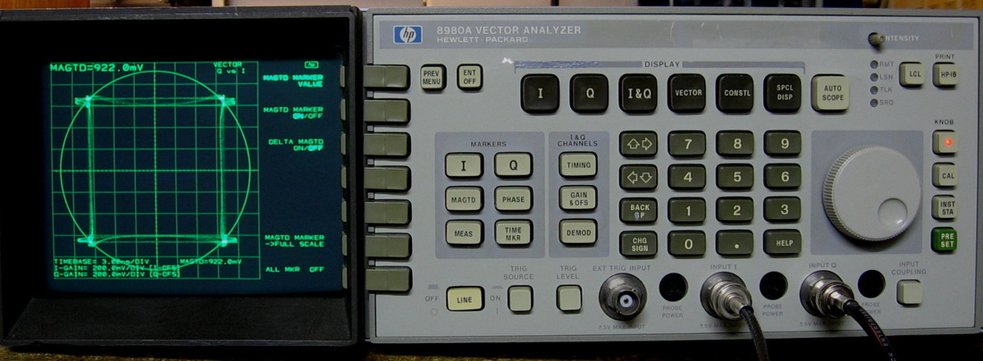
HP 8980A: The HP 8980A is a specialty piece of equipment called a Vector Analyzer. Think of it as a two-channel oscilloscope with a variety of displays. It is meant to measure the I- and Q- outputs of a demodulator. Many of its simplest functions could indeed be done with a two channel scope in the X vs. Y mode, but the problem with a scope is that while the vertical bandwidth is usually quite high (hundreds of MHz), the horizontal bandwidth is quite low (tens of MHz); this leads to a distortion in the scope's X vs. Y display. The HP 8980A does it correctly and is probably why it cost $25,000 in the 1990s. I don't have the proper vector signal generator, but at least I can give it two identical pulse trains offset in time. The picture shows one particular display, the Vector display, where one observes the HH, HL, LH, LL possibilities hitting the four 45 degree quadrant points (this is similar to what QPSK would produce). The 8980A is rated DC-350 MHz, but in typical HP fashion, I've run it to 420 MHz without problems. (OM) Grade: A-
I'm glad I didn't start my TE repair career with this piece after having plunked down $60 for the service manual since it might have cured me right there and then. The manual contains some brief adjustment information, then runs through page after page of procedures to isolate problems to a particular board (this involves a lot of menus setting internal parameters). The conclusion to each procedure, once the board has been found faulty, is to send it back to HP for exchange. NO schematics. NO parts list. NO parts layout. Just a few overall block diagrams and page after page of procedures. Even the adjustment procedure is incomplete, particularly for the display (one adjustment to set the focus range). Well, the display turns out to be an HP 1345A digital display used in many different pieces. Fortunately, that manual is perfectly reasonable and I spent 1-1/2 hours tweaking the 20 or so pots to perfection. NO mention of any of this in the 8980A manual, only a weak reference to the HP 1345A. As far as performance, the only thing wrong I can find is an error in the Q-channel delay readout. The unit allows you to delay the I, Q or both channels up to a few microseconds. If you crank in 20 nsec delay on the I-channel, the waveform moves 20 nsec. If you crank in 20 nsec delay for both I and Q (as one common number), both waveforms move 20 nsec. But crank in 20 nsec delay on the Q channel alone, and it moves about 6 nsec. You can delay the channels, it's just the readout on the Q-channel that is wrong. They use three separate D/As to control I, Q and both I and Q, and I suspect one of them may be faulty. But without the schematic, all I suppose I can do is figure out which IC it is and buy another. Funny, when you use the factory default calibrations, it almost works correctly on the Q-channel. But then the whole unit is way out of whack. Perform the regular calibration and the Q channel delay is about 3x low. So my guess is that the D/A probably doesn't have enough range to make a good calibration constant. I thought about loading the factory defaults and then trying to calibrate it. But there clearly aren't enough adjustments listed in the manual and every step of the manual says to start with pushing the front panel CAL button (which overwrites the defaults). Oh well, I don't really even see why I would ever need to delay more than one channel independently of the other. I mean, just switch the input connectors if necessary and always use the I delay.
Postscript: Preemptively replaced the 0.1 uF Rifa X-capacitor hanging off the power switch with a 0.1 uF non-Rifa X-capacitor.
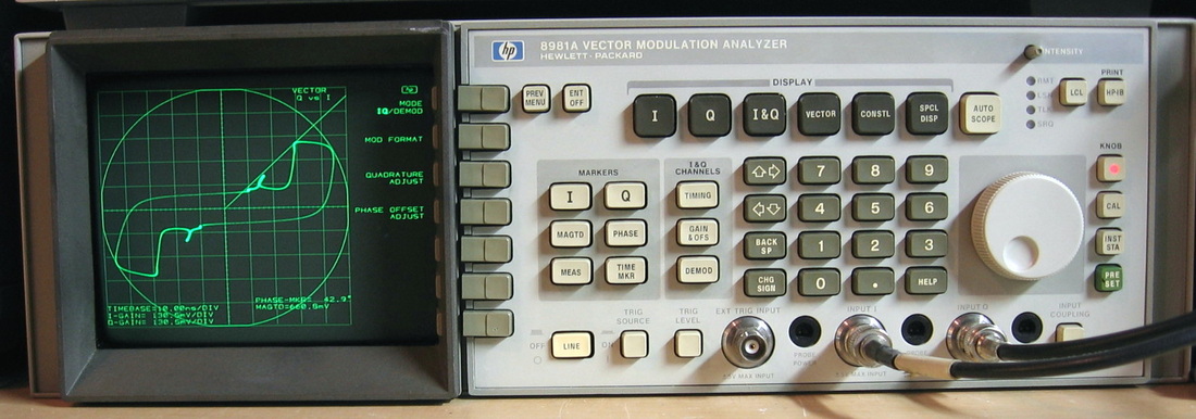
HP 8981A: Vector Analyzer with Demodulator. The HP 8981A is identical to the HP 8980A (see above) except that it has extra hardware and software ($5K) to internally demodulate signals with up to 100 MHz bandwidth. Whereas the HP 8980A requires both an I- and Q- input, the HP 8981A can generate these two by demodulating an input signal. I was moderately happy with my HP 8980A except that there was a small malfunction in the Q-channel delay which I never got to the bottom of. I picked up the HP 8981A for less than fifty bucks and my intent was either to use some of its boards to fix my HP 8980A or use some of the 8980A's boards to fix the 8981A. It didn't quite work out that way. (OM/PDF) Grade: A-
This piece was advertised by the seller as broken. The eBay picture showed a bright green blob in the middle of the display and nothing else. Before pulling out boards to put in my HP 8980A, I at least owed it to myself to take a look at what was going on. Not that I was deterred by the attached yellow tag from some calibration lab that said, "Unit heavily tampered with - not economical to repair." When I opened it up, two of the four status LEDs on the power supply board were unlit. However, the test points showed all the voltages were fine (the two LEDs had blown). The display portion is a modified HP 1345A and I had a manual that was close enough. The 5, 15 and -15 volt supplies in the display were fine, but then I noticed one of the cables from the display P/S to another board in the display was pulled off. I reinstalled the cable and the green blob on the CRT disappeared. But so did the 15 volt display supply which propagated back to the main unit and turned off that supply. I did some further dissection to get to the display board, disconnected the board and measured from the 15V test point to ground. About 0.5 ohms. Then I looked around and saw that the previous owner had lifted and resoldered a few capacitors in a vain attempt to locate the short. I also checked the -15 volt line and found that it had also shorted to ground. Well, the schematic was close, but not perfect, so I hooked up the ohmmeter across the 15V line and started clipping capacitors until the short disappeared. Same deal on the -15V line. Hooked everything back up, threw the power switch and the display now read "Starting self-test," followed shortly thereafter by "Self-test passed." Then the display showed what looked like unsync-ed video gyrating all over the place. The HP 1345A display is basically a vector display that is programmed by the host. But HP decided while that was good for text and grids, they wanted the signal trace to essentially be an analog display, not drawn by computing x-y vector points. So they run the vector generated x- y- and z- signals out of the 1345A display into the 8981A CRT Switch Board where it is multiplexed with the x- y- and z- analog signals and the whole mess is put right back into the 1345A display. This switching is controlled by a sync pulse from the 1345A display and I was not seeing that or the correct signal on the CRT Switch Board test point. So I pulled out the CRT Switch Board from the working 8980A and tried that - no luck. At this point, I was kind of perplexed, but I had the 8980A open so I tried using the 8980A's uP and RAM boards in the 8981A. Worked great. I put the 8981A uP board back and it still worked. So that left the problem on the 8981A RAM board. I lifted the almost dead battery out of it, installed a new battery and then put the card back in. Now everything worked. Whether it was simply a reseating problem or a corrupt RAM that I cleared, who knows. I thought I was all done, but then I noticed that the display's text was kind of fuzzy - almost like the characters had echoes. I remembered that I never bothered to reconnect all the good capacitors that I clipped, and after I did that, all was well. I went back and cleaned up the capacitors, replaced the two faulty 2.2 uF tantalums that were at the root of the initial problem, installed new LEDs to monitor the main P/S voltages and calibrated what I could. So my HP 8980A still has a problem with the Q-channel delay, but I have a fully functional HP 8981A now which, of course, is the more desirable unit anyway.
Postscript: Preemptively replaced the 0.1 uF Rifa X-capacitor hanging off the power switch with a 0.1 uF non-Rifa X-capacitor.
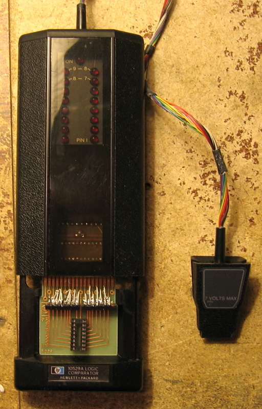
HP 10529A: HP called this a logic comparator and was only produced a few years in the era right before full logic analyzers became mainstream. It was often bundled with other logic analysis devices such as the HP 545A logic probe, HP 546A logic pulser and HP 547A current tracer. The operation and concept is pretty basic - put the 10529A clip on a suspected defective IC in the unit under test. Put a known IC of the same type on a "reference" card and slide it into the 10529A. The 16 LEDs in the 10529A will then flash for any IC pin that is defective, i.e., doesn't match the reference IC. The 5V power for the 10529A is also drawn from the IC in the unit under test. Now when installing the known good IC onto the reference card, you must separate the corresponding top and bottom edge connector pins for any line that corresponds to an output of the IC. The instructions are to drill through the via connecting top and bottom. Of course, once you've done this, the reference card can only be used with another IC if the output pins are the same. So HP gave you 10 blank reference cards and sold additional ones for <$10 each. After numerous complaints I suspect, HP came out with a "universal" reference card that provided the output line disconnects via DIP switches. Too bad the unit I bought didn't come with it (or is it???). (PDF) Grade: B+
The unit came with about a dozen reference cards all with various ICs soldered in. I selected the one with a 74174 on it and hooked the 10529A up to a 74174 inside an HP 3455A DMM. Unfortunately, LEDs #1 and #8 lit, as well as the power on LED, and the three LEDs were quite dim. I opened the unit up only to find that the circuitry had a Vcc of about 2.5V, not the 5V it was drawing from the chip in the HP 3455A. Further poking around showed that ground wasn't connected in the 10529A to about half of the circuitry. The board in the 10529A is three layers and a lot of Vcc and ground are propagated in the middle layer (which can't be seen easily). I don't know what's the story, but it's almost like the middle layer was disintegrating before my very eyes. To make a long story short, I also found two defective ICs and a defective zener, once I wired around the middle layer defects. HP set the logic threshold to 1.4V, which is marginal by today's standards, and so when I replaced ICs, I had to lower the pull-up resistors. Now that the 10529A was working, I actually wanted to try something other than a 74174. So I built my own "universal" reference card which is shown in the picture sitting in the drawer waiting to be pushed inside the 10529A. My card has a 16 pin DIP socket and two 8-position DIP switches whose individual switches are set to off for any output line. I also built a 14 pin version and two "test" cards. The first test card puts the upper half of the edge connector at 5V and the lower half at 0V; this causes all the LEDs to turn on. The second test card shorts the upper and lower halves together and keeps all the LEDs off. This gives me a basic functional test of the 10529A circuitry (excluding the actual IC clip).
The unit came with about a dozen reference cards all with various ICs soldered in. I selected the one with a 74174 on it and hooked the 10529A up to a 74174 inside an HP 3455A DMM. Unfortunately, LEDs #1 and #8 lit, as well as the power on LED, and the three LEDs were quite dim. I opened the unit up only to find that the circuitry had a Vcc of about 2.5V, not the 5V it was drawing from the chip in the HP 3455A. Further poking around showed that ground wasn't connected in the 10529A to about half of the circuitry. The board in the 10529A is three layers and a lot of Vcc and ground are propagated in the middle layer (which can't be seen easily). I don't know what's the story, but it's almost like the middle layer was disintegrating before my very eyes. To make a long story short, I also found two defective ICs and a defective zener, once I wired around the middle layer defects. HP set the logic threshold to 1.4V, which is marginal by today's standards, and so when I replaced ICs, I had to lower the pull-up resistors. Now that the 10529A was working, I actually wanted to try something other than a 74174. So I built my own "universal" reference card which is shown in the picture sitting in the drawer waiting to be pushed inside the 10529A. My card has a 16 pin DIP socket and two 8-position DIP switches whose individual switches are set to off for any output line. I also built a 14 pin version and two "test" cards. The first test card puts the upper half of the edge connector at 5V and the lower half at 0V; this causes all the LEDs to turn on. The second test card shorts the upper and lower halves together and keeps all the LEDs off. This gives me a basic functional test of the 10529A circuitry (excluding the actual IC clip).
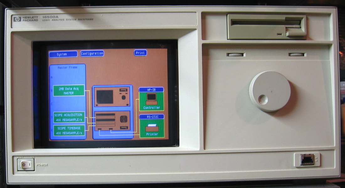
HP 16500A: Logic analyzer mainframe with 16-channel acquisition and a 2-channel oscilloscope. Requires the OS to be loaded by floppy every time it is turned on. The scope may go to >100 MHz, but it's only 6 bits! Nice touch screen. I'm sure HP impressed everybody with the nice color screen, but the thing is horrendously slow and extremely cumbersome to use. And who wants to fish out the floppy disks every time you turn it on? I'll use the HP 1630G, thank you. (OM) Grade: B-
No electrical problems, but the front floppy drive didn't work. I dissected the drive and fixed the pawl and gear.
No electrical problems, but the front floppy drive didn't work. I dissected the drive and fixed the pawl and gear.
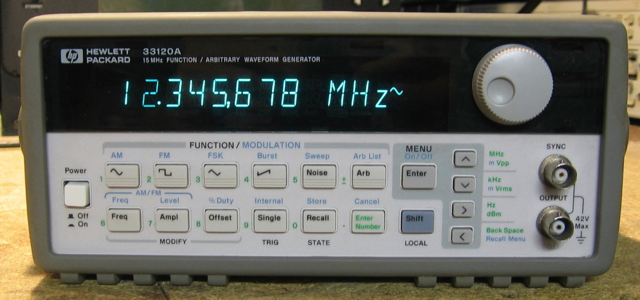
HP 33120A: 15 MHz function generator. The 33120A is a mid-1990's synthesized function generator featuring sine, triangle, square, ramp and noise waveforms. It also has a 12-bit, 40 MSamples/sec, 16K-deep arbitrary waveform generator. Mine has Option 001, Phase Lock Loop, which adds a high stability timebase and the ability to phase lock to external source or a second 33120A. One of the first of HP's modern function generators, it has a VFD display which will eventually dim, and a menu system that is, to say the least, a bit cumbersome to use. But once you get the hang of it, the 33120A is very capable with lots of functionality. And after I calibrated it, I found the 33120A to be exquisitely accurate. (PDF) Grade: A
There was nothing overtly wrong with the 33120A, but the output voltages looked a tad high. So I ran through the performance tests and quickly discovered that the unit was out of spec. I then marched my way through the 85-step calibration procedure. Each step sets up the machine to output a certain frequency and voltage. You then measure that with a DMM, for example, and dial in your reading back on the 33120A's display. Then it's on to the next step. It was clear from the display that about 1/3 of the 85 calibration parameters were at their default values and had never been changed, despite there being about 4 previous calibrations (according to the calibration count number). And many of the values that were adjusted were way wrong, by as much as 10%. After I got through with my complete calibration, the unit passes all of the performance tests. In fact, each performance test provides limits on the acceptable error. I'm beating the limits by almost 10x on every one.
There was nothing overtly wrong with the 33120A, but the output voltages looked a tad high. So I ran through the performance tests and quickly discovered that the unit was out of spec. I then marched my way through the 85-step calibration procedure. Each step sets up the machine to output a certain frequency and voltage. You then measure that with a DMM, for example, and dial in your reading back on the 33120A's display. Then it's on to the next step. It was clear from the display that about 1/3 of the 85 calibration parameters were at their default values and had never been changed, despite there being about 4 previous calibrations (according to the calibration count number). And many of the values that were adjusted were way wrong, by as much as 10%. After I got through with my complete calibration, the unit passes all of the performance tests. In fact, each performance test provides limits on the acceptable error. I'm beating the limits by almost 10x on every one.
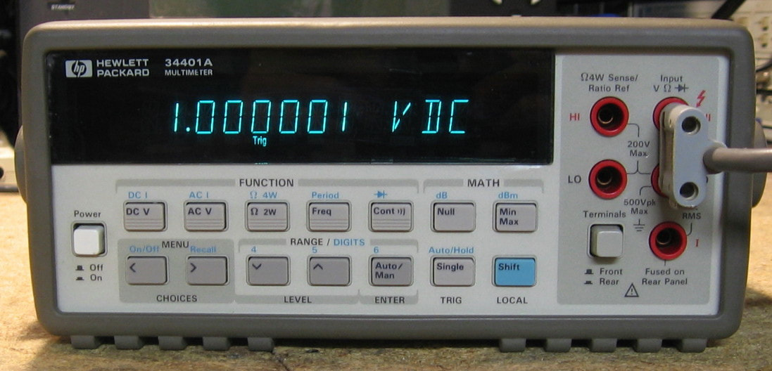
HP 34401A: 6-1/2 digit DMM. The 34401A was HP's most successful "low cost" general purpose bench DMM. I won't go into any detail on the specifications, because you either own one, use one at work, or know someone who has one. If you really need to know the specs, google it and you will get 50,000 hits. HP categorized this DMM as a 15 ppm class device. That may be true on the 10 VDC range, but I consider it mostly to be a 30 ppm device. I don't like the 34401A as much as my comparable Keithley 2015THD or Keithley 6500DMM in terms of navigating through the various settings. And I find the 34401A takes a good 60 minutes to warm up, a lot longer than the Keithley meters or other HP bench DMMs like the 3456A and 3457A. (PDF) Grade: B+
The unit passes all self-tests and seems perfectly accurate, although a 10.00000 VDC calibration source will read 9.99980 when first powered up and takes a good 60 minutes to hit 10.00000. I did find one other anomaly, however. I let the 34401A sit for an hour measuring DCV and when I returned, the unit had switched itself to ACV. Hit the DCV button, went back one hour later and it had switched back to ACV yet again. A suggestion as to the fault said that a momentary power interruption could possibly cause the switching. So after I verified that the 5V analog, 5V digital and +/-18 volt power rails had negligible ripple, I put a scope on the 5 volt analog rail and set the scope to trigger on a downward edge to 4 volts. Let the 34401A run for four hours and it never switched to ACV, nor did the scope trigger. I've since run it for another couple of hours and it didn't switch. So I am at a loss at this point. If it starts happening again, I will dissect the front panel and look for debris near the ACV button contacts.
The unit passes all self-tests and seems perfectly accurate, although a 10.00000 VDC calibration source will read 9.99980 when first powered up and takes a good 60 minutes to hit 10.00000. I did find one other anomaly, however. I let the 34401A sit for an hour measuring DCV and when I returned, the unit had switched itself to ACV. Hit the DCV button, went back one hour later and it had switched back to ACV yet again. A suggestion as to the fault said that a momentary power interruption could possibly cause the switching. So after I verified that the 5V analog, 5V digital and +/-18 volt power rails had negligible ripple, I put a scope on the 5 volt analog rail and set the scope to trigger on a downward edge to 4 volts. Let the 34401A run for four hours and it never switched to ACV, nor did the scope trigger. I've since run it for another couple of hours and it didn't switch. So I am at a loss at this point. If it starts happening again, I will dissect the front panel and look for debris near the ACV button contacts.
HP 34401A Bonus Rant: Let me preface all of this by saying perhaps there is some subtle fault in my particular unit. Also, mine is a relatively early example. But as I alluded to in the descriptions above, I find the 34401A lacking in comparison to the comparable Keithley 2015 and 6500 6-1/2 digit DMMs. Both of the latter units power up (input shorted on DCV, 100 mV range) with <3 uV offsets and within 10 minutes are down to <1 uV where they remain. The 34401A powers up with >10 uV offset and it takes a good 90 minutes to get down to 1 uV. The spec suggests a two-hour warmup time, but maybe HP could have paid more attention to thermal management in their design. Once warmed up, however, it is very stable. I shorted the inputs and for the next four hours, the meter didn't move past +/-0.3 uV. But I find the 34401A menu system horrible. And, worse than all of that, my unit occasionally will switch itself from DCV to ACV. Several people have reported on the various forums that their 34401As also randomly switch functions and the forum respondents have always suggested cleaning out possible debris behind the front panel buttons. But I, and the other poor souls, have done this to no effect. I haven't seen anybody present a solution. So, while the 34401A was the 6-1/2 digit DMM industry standard for decades, I really am not a huge fan.
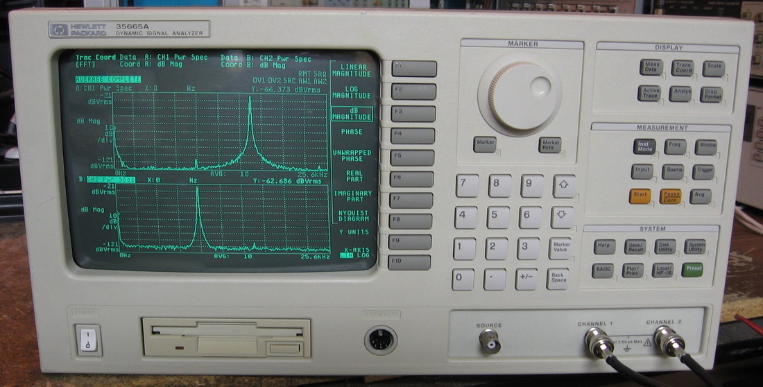
HP 35665A: Two-channel, 100 kHz dynamic signal analyzer. In other words, your basic FFT engine. Shown in the picture measuring two sine waves on the two channels (note you can see the channel crosstalk down about 85 dB) This was the follow-on to the HP 3562A DSA that I also own. A slightly earlier version of the 35665A (the 35660A) was also produced and the follow-on to the 35665A, the 35670A, is still being sold today for ~$23K. I'm not sure why HP abandoned the 3562A because I think it is actually a better implementation than the 35660/5 series. Perhaps they were having trouble getting parts. I also like the HP 1345A vector display in the 3562A much better than the standard CRT in the 35665A. A nice feature (not available in the 3562A) is a waterfall display of the spectrum over time. As far as specs, some of the 3562A specs are better and some are worse. The (50 ohm terminated) noise floor in the 35665A is about 20 nV/rt-Hz and about 40 nV/rt-Hz in the 3562A. The FFT update rate is also faster in the 35665A. I suppose these things are just are reflection of the improved parts available a decade later. My unit has a few software options enabled. The 2M RAM expansion board is installed, but not currently enabled in the EEPROM holding the configuration. Would make for a good hack one day. (PDF) Grade: A-
Bought on eBay for $140 + shipping which is a bit pricey for me, but a fairly good price for this particular unit. It was advertised as "blows fuses." When I received it, there was an intact 3A fuse installed, even though the fuse holder clearly says 6A required. I thought maybe the seller tried a bunch of 3A fuses and finally gave up in disgust. It couldn't be that easy, could it? This time, it wasn't as my newly installed 6A fuse shattered immediately upon plugging the unit into AC. I yanked out the TRW-made switching P/S (produces 8 different voltages) and proceeded to dissect. The only visible burnt parts were the two inrush thermistors, although they actually tested about 30 ohms (nearly correct). I then hooked up the P/S to the Sencore isolation transformer (with another 6A fuse installed) and slowly cranked up the voltage. The unit drew 2A with an input of 8 VAC, so there definitely was a short somewhere. It didn't take me long to locate the main switching transistor which was shorted across all three leads. So was the MOSFET that drives the switching transformer, and so were three 1N4148s and three 5.6V, 5W zeners. That appeared to be the extent of the carnage. The two thermistors, two transistors and six diodes were procured and installed. No more short. So back inside the 35665A the P/S went and I fired it up. Fans whirred, relays clicked, board diagnostic LEDs lit, but the CRT was completely dark. I had seen an eevblog video where they fixed a dead CRT on the similar 35660A. What had happened was that the neck board had gotten unplugged from the CRT tube. It couldn't be that easy, could it? This time, it was. I pulled the CRT unit, took off the covers, and there was the neck board flapping in the breeze. I plugged it in, but it seemed a bit tight. When I fired up the unit, I saw a picture on the CRT, but it was only about 2 square inches in size. To make a long story short, the entire yoke must have broken free and slid back on the tube, knocking the board off the pins. Well, the yoke pushed back only an inch or two on the tube, before disappearing underneath a metal shield. So I couldn't really see what was going on, and I was meeting substantial resistance as I pushed further. Finally, I heard something snap and the assembly slid all the way back. However, all is not perfect, as the magnets must have moved ever so slightly giving me the trapezoidal geometry shown in the picture. Maybe one of these days I will attempt an adjustment, but the chances are just as high that I make it worse.
Postscript: The 35665A has been acting up lately, either refusing to start or starting up and then quickly shutting down. If you toggle the power switch a few times, it eventually does start (and passes all self-tests). It also seems to be OK if you use it frequently, but let it sit a few weeks and the problem returns. I first thought it was maybe some deterioration in the capacitors in the power supply and I tore open the supply and took a look. All the capacitors seemed fine, but I did replace a couple in the startup circuitry - this did not fix the problem. Then it dawned on me to follow my own advice described in the Repair section at the bottom of this web page, namely always look for mechanical problems first. Indeed, the AC line runs through the front panel power switch and I was getting 20 to 30 ohms through the switch, but sometimes dropping to a few ohms after toggling the switch a bunch of times. At a few amps of current draw, the voltage drop was enough to prevent the supply from starting. I replaced the switch and cleaned the connectors and hopefully that will fix the problem once and for all.
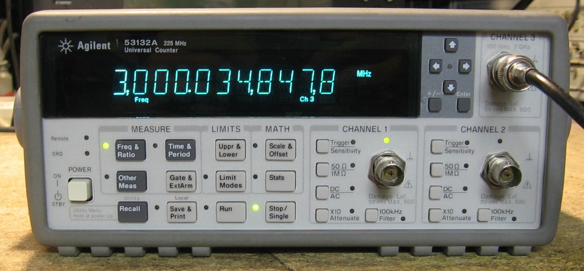
HP 53132A: 225 MHz Universal Counter: This counter does the usual functions with a 12-digit display. Mine has the 3 GHz Channel C option, the Option 010 OCXO, and the rear panel input jack option. Like most of HP's equipment in the 1990's with a VFD, the menu system is a bit awkward. I have penalized HP's grade for the 53132A because of two stupid design errors: 1) the fan stays on (and the unit draws 20 watts) whenever the unit is plugged into AC, regardless of whether the unit is turned on or not; and 2) the optional rear panel input jacks are engaged and in parallel with the front panel input jacks - there should be a relay to isolate which pair are being used (see the repair notes below). One could make the argument that you don't want heat to build up inside, especially with the OCXO (even if it is thermally insulated), because the stability would be affected - hence the need for the fan. Funny, because HP's other counters, like the 5334A/B which use the same OCXO, don't have fans. So I'll cut HP a little slack on that one. But the issue with the front and rear terminals seems like a stupid mistake. (PDF) Grade: B+
When I received this piece and powered it on, it threw a ROM checksum error. However, the counter seemed to work fine, so whatever bit(s) were wrong in the program memory, it didn't seem to affect anything. Then I started to play around with various input signals and noticed the counter had about 20 dB reduced sensitivity from 100 to 150 MHz on both the A and B channels. I should have read the manual carefully because there is a footnote in the specifications about the rear panel input options. Both the front and rear panel jacks (channels A and B) are both on at the same time. So if you inject a signal into the front panel, it travels back to your unterminated rear panel jacks, reflects back to your input, and the standing waves cause attenuation. The simple remedy is to terminate the back panel jacks (if using the front panel input) or vice-versa. As far as the corrupted ROM, this appears to be common in units >20 years old. A new set of AM20F010 flash memory chips and an PLCC-to-DIP adapter for my programmer are on order. Stay tuned...
Postscript: I removed the Option 060 rear panel input jacks. I have no intention of using them and they only serve to reduce the sensitivity of the 53132A when they are installed. Bye, bye.
Postscript^2: Programmed up a new set of ROMs and voila - all fixed. A forensic analysis of the old ROMs showed that there was one incorrect byte near the end of U8. The correct byte is supposed to be FF, but it read EF. Since this error was in a block of FFs, all at the end of the U8 address space, my guess is that it wasn't being used by the 53132A's actual program. Thus the only consequence was the ROM error at startup.
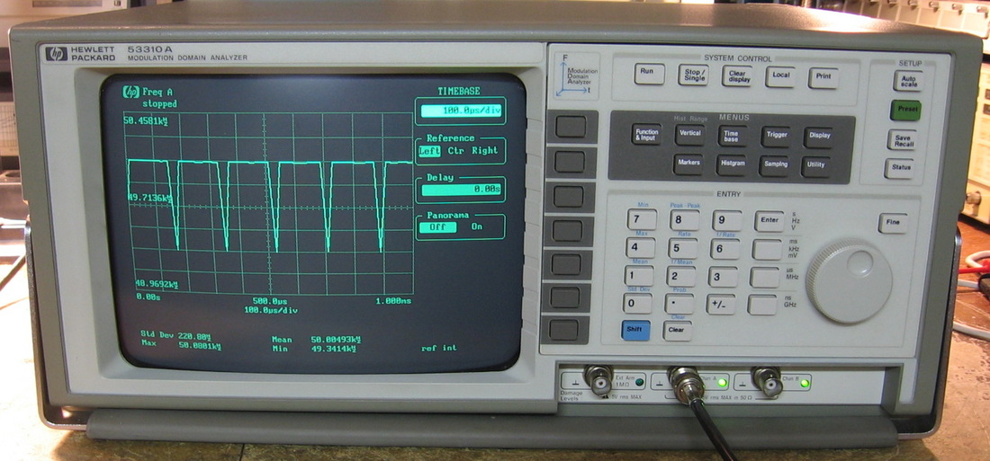
HP 53310A: Modulation Domain Analyzer: This curious piece, while called a modulation domain analyzer, is essentially a high speed counter that graphs the results. An oscilloscope graphs voltage vs. time and a spectrum analyzer graphs voltage (or power) vs. frequency. This piece graphs frequency vs. time. One would use this to characterize VCOs for instance. There are two basic modes: 1) frequency vs. time and 2) histogram of frequency; the picture shows the first mode. Control-wise, the unit acts sort of like an oscilloscope in that there are timebase controls, amplitude controls and triggers. However, one must remember that the y-axis and the triggers are based on frequency, not voltage. It gets sort of confusing. Fortunately, there is an "auto-scale" button that pretty much takes care of all the settings. The 53310A is based on a custom HP hybrid counter chip that is capable of doing >1 million measurements per second (each measurement is the result of a much higher basic count). The signal inputs are capable of handling a 200 MHz signal. As an example, the photo shows my HP 8904A function generator outputting a 50 kHz square wave into the 53310A. Remember that the 8904A is a strange beast in that it is all table-based waveform lookup. The basic rate into the table is 1.67 MHz meaning that a 50 kHz waveform is a 33.4 multiple of that basic interval. The 0.4 in the 33.4 means that the table lookup has fractional addresses which results in picking the nearest integer address into the table. This induces at most a 1/1.67MHz = 600 nsec jitter to the square wave (which is clearly visible on a scope). Because of this jitter, not every successive T units of time are going to see exactly the same number of pulses. And that is exactly what the 53310A shows, with the frequency dipping down to 49.34 kHz somewhat periodically. I am going to deduct a full grade from this because HP in their infinite wisdom decided to put the power switch on the back panel. I've often seen HP put a master switch on the back, but at least then they always had the courtesy to put a secondary power switch on the front panel. Not on this piece. (PDF) Grade: B
Postscript: Perhaps I should increase the grade back up from a B to an A, because I am less annoyed with the rear panel power switch. I am, however, extremely pleased with the capabilities of this unit. HP didn't do a very good job of marketing this piece, because in reality, it can do some amazing things like 14 digit frequency measurement and sub 1 nsec rise time measurements. But that's if you take the time to understand how to use it. Unlike 99% of the stuff I have, the 53310A functionality cannot be duplicated by my other pieces.
Advertised as working, it basically was when I got it. It was failing the cal procedure, but a fresh cal wrote new values into the NVRAM and fixed that problem.
Postscript: A couple of weeks after I got this, the unit suddenly powered off. A quick check of the 3A line fuse showed that it had popped. I put in another only to see a big flash emanating from the partially sealed switching P/S. Dissecting the supply, the internal 5A fuse had popped. I replaced it with a 6A fuse (the closest value in my junkbox) and powered it up through the Sencore isolation transformer. The Sencore meter showed a small inrush current, followed by zero current draw. These power supplies are from a third party vendor (something HP did a lot in the 1990s) and are also used in the HP 545xx oscilloscopes. Someone had reverse engineered the supply and conveniently posted a schematic online Probing my way through the primary circuitry to the switching transistor, everything looked OK. But the transistor showed a short across base-to-emitter. I pulled the transistor, but the short remained on the board. Luckily, I tested the transistor - totally open on all three leads. So besides a blown transistor, I still had a B-E short on the board. From the schematic, the only component that could cause the short was something labeled S1. I pulled that component and it was shorted (and the short disappeared from the board). The component is marked MTS90A, and from the various forums, seems to be a thermal switch. The idea is that if the P/S overheats, the switch closes and shorts the transistor B-E, turning off the transistor and thus the supply. Nowhere can I find anything about the MTS90A, nor can I find one for sale. So out it goes, period. As far as the blown transistor, it is a TIPL755A 420V/10A/180W NPN and all I had in the junkbox was a BU208A 1500V/8A/150W. Close enough for me. The new transistor was installed and the unit seems fine now
Postscript^2: The "unit seems fine now" in the above Postscript was a bit too optimistic, I'm afraid. After being left on for about 15 minutes, the CRT on the 53310A went dark. Moreover, the LEDs on the front panel were flickering slightly. I dissected the P/S once again and found nothing visibly wrong. A check of the 5 volt test point showed the voltage randomly varying between about 2 and 4 volts. There was also a very faint crackling sound. I was about to check the switching waveform on the base of the main transistor when I noticed that the heat sink was red hot. This was followed shortly by smoke and the supply went totally dead. A check of the transistor showed a C-B short which of course fried some resistors in the base circuitry. After scratching my head all morning and finding nothing wrong with the primary circuitry, I began looking at the secondary side. What's that, a little black discoloration under one of the 220uF/50V output caps? I pulled the cap only to find a puddle of electrolyte ooze sitting beneath it. So leaving nothing to chance, I pulled all 29 output caps. Nine of them had leaked, and, in fact, all seven 220uF/50V caps were among the leakers. Must have been a real bad batch. Leaking electrolyte might explain the crackling noise, lack of regulation and the overheating of the switching transistor (it is on an fairly anemic heat sink). Luckily I pulled that temperature protection switch so I could see the transistor fry in front of me New caps and transistors are now on order
Postscript^3: 29 new electrolytic caps were installed, but I didn't yet have the TIP755A from Hong Kong. So I ran some jumper wires to an NPN TO-220 transistor pulled from an old computer power supply and fired the thing up. Immediately popped the transistor with a C-E short. Tried a second transistor and the same thing happened. Eventually, I received the TIP755A and that didn't pop, but the P/S didn't start either - it simply ticked. So there are definitely more problems. As a last resort, I bought an HP 1650A logic analyzer for $35 which, according to the service manual, has the same P/S. But the service manual also mentions a "Type 1" and "Type 2" supply, and as luck would have it, the supply I got in the 1650A was the wrong one. It had an adequate amount of power and produced 5, -5, 3.5, 12 and -12 VDC - everything I needed except 15 volts for the chassis fan (which can run fine on 12V). The output connector was 16 pin, not 20 pins like in the correct 53310A supply. So I had to manufacture a cable that went from 16 pins to 20, duplicate some connections, and then wire up 12 volts to the fan. I also needed some sheet metal work to get the thing to fit into the 53310A. Seems to work fine now. Any more problems and I'm going to buy two Meanwell switching supplies and build my own.
Final Postscript: I was bored and I didn't like removing the supply from the HP 1650A (which was also not the correct one for the 53310A), so I spent about $35 and bought a Meanwell RT-65B to supply 5, 12 and -12 (and also 3.5V with two diodes from the 5V) and an RS-25-5 to supply the -5 volts. Mounted everything on the top cover of the old switching supply turned upside down with some minor sheet metal refabrication. Works great and I shouldn't have any problems for the next 20 years. And it now only draws 85 watts from the AC line rather than the original 120 watts (the original Boeschert switching supply had its fair share of regulators and pass transistors on the secondary) Runs nice and cool.
Final, Final Postscript: Well, my buddy needed a display board for his 53310A and I could always use the correct P/S, so we shelled out $35 for a unit described as "interpolation calibration failed." Turns out that the error was caused by a marginal P/S (I should have guessed this) which died about 5 minutes after I turned it on. Great - remember the last time I tried to fix this Boeschert supply (see above)? I wasn't exactly successful. So I opened up the P/S only to find electrolyte all over the place. I removed the 29 caps and I would say at least 20 of them were bulging/leaking. At that point, I removed the 29 new caps from my previously attempted fix and installed them into this supply. Still no joy as the 5V supply could only reach about 4.5V and was very touchy if I tried to adjust the switching oscillator frequency. I exchanged a lot of active components with the old supply, but nothing helped. At one point, I removed the optoisolator which then cuts the feedback loop only to find that nothing changed. At that point, it was clear that something was simply bringing the 5V line down a bit. I found an SCR on the control board and in desperation clipped two of the three leads. Voila, the 5V line came up and I was able to properly adjust the 12, -12, 3.5 and -5V rails (only after I replaced the adjustment pot on the -12V line that I had damaged by chiseling off the epoxy seal). Just for fun, when I was all done, I hooked back up the SCR. Still worked perfectly - go figure. The best explanation I can come up with is that all the voltages or "or"-ed into the SCR and the thing was way out of adjustment (since I turned all the pots many times in a futile attempt to get the thing to work). That dragged down the 5V supply which serves as the reference for the SCR trigger and the thing got stuck since one or more voltages was then too high with respect to the reference. Only after I removed the SCR was I able to properly adjust everything and then the voltages were OK after reapplying the SCR. I prefer this original P/S to the one I built because the homebrew supply is very noisy and causes the 53310A to exhibit a few artifacts in the count with signals near the switching frequency (~50 kHz). None of the artifacts with the original supply. Stay tuned...
Final, Final, Final Postscript: Saw a post on the web about installing Option 001, Expanded Memory. Bought four CY7C194-20 64Kx4 memory chips, configured a few jumpers, and voila - expanded memory.
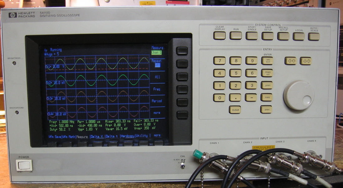
HP 54112D: Four channel, 100 MHz digital sampling oscilloscope. The 54112D (and its big brother, the 500 MHz 54111D) were developed in the late 80's and were among HP's first foray into digital scopes. Sort of like the Chevy Vega and Ford Pinto were GM and Ford's first foray into fuel efficient cars - we all know how that turned out. This unit samples at 400 MHz so it truly has a one-shot bandwidth of 100 MHz. The bandwidth is not restricted to repetitive signals as many "compromise" digital scopes are (those scopes essentially sample a waveform asynchronously so that it builds up completely over many cycles). However, it feels like HP figured out how to build a digitizer and put the waveforms on a color CRT. It was only then that they thought, "hey, we can make an oscilloscope out of that." The user controls are not what a scope user really wants. Every function must be selected from menus via soft-keys on the bottom and/or right of the CRT and then the knob (or keypad) used to make the adjustment. Real scope users want separate knobs for vertical, horizontal, trigger, etc., that are easily accessible without a lot of punching keys. And find me another real scope that has a numerical keypad. Although, I have to admit that it is nice to be able to type in 234 mv/div when I want to. The scope has a nice auto-configure function that examines the inputs and also has an extensive automatic measurement capability. There are a few odd trigger functions that look like they were borrowed from a logic analyzer. On the other hand, there are some missing things like the ability to ground a channel. All in all, very nice for 1988; not so nice afterwards. HP quickly came out with the 54600 series about five years later and they put the 54112D to shame by comparison (although their one shot bandwidth is low). The improvement in the 54600 series is most apparent in the waveform update rate which is orders of magnitude higher than the rather paltry (~30) update rate of the 54112D. The 54112D certainly deserved an A grade back in the day, but I have to deduct points for the user interface and for only effectively a 6-bit digitizer. Grade: B+ (PDF)
This is going to be a long description, so take a deep breath. But based upon the amount of time and effort I spent with this unit, the long description is entirely justified. I paid $80 on eBay for this from a seller who advertised only two of the four channels working correctly. His description was perfectly accurate: channel #1 and channel #2 were fine, channel #3 and channel #4 were "noise." While I was pondering that, I noticed that the display wasn't very bright. Moreover, the colors in the top third of the display were a bit off and the rectangular background grid was a bit compressed, but only between the 7th and 8th divisions. I tweaked every one of the about 20 pots on the display driver boards to no avail. The CRT (a Sony Trinitron) takes 120VDC from the main P/S and I measured only 95V at the test point. I disconnected the P/S and pulled it out. Unloaded, I still was only getting 95V, so that's the good news (P/S fault, not display fault). In my past experience, I noticed that HP often put Zeners on the output of their supplies as over-voltage protection and I've seen them partially fail and drop down the supply voltage. Perusing the board, I didn't see any Zeners close to the 120V output, but I did see two 3-terminal TO-92 devices. The transistor tester lit up on one but not the other. So I pulled them both out and put them on the Peak Component Tester. Again, one was "OK" (identified as two diodes) and one was "No Component Detected." Looking up the HP part number, the devices were found to be TL431 adjustable shunt regulators, i.e., an adjustable Zener. So my initial Zener guess was correct. I ordered some replacements and the new one brought the 120V supply back to 120V and cured all my display problems.
The next order of business was to take care of the probe calibration terminal on the front panel that had snapped off. Fortunately, a simple capacitive feedthrough I found in the junkbox mounted in nicely and gives me a little post to hang the scope probe onto.
Returning to the guts of the 54112D, the first order was to dissect and clean the four input pods (each pod contains solenoid-controlled attenuators and preamp and trigger hybrid ICs). HP was proud of these custom input pods and has an article in the HP Journal dedicated to them. Working on these is not for the faint of heart as they contain microscopic little spring contacts. One wrong move and they will fly across the room never to be seen again. A few nerve-racking hours later, I had disassembled, cleaned and reassembled the four pods. That kept channels #1 and #2 working, and now channel #3 showed up correctly, except that the unit wouldn't trigger on channel #3. Channel #4 would occasionally show up depending on the V/div, impedance selection and offset value, but then would quickly disappear. And when the trace was there momentarily, it also wouldn't trigger on channel #4. The scope has four A/D boards for the four pods. By switching boards, I determined that the malfunction was most likely the fault of the boards, not my recently worked input pods. Well, good luck fixing the A/D boards with no schematic, no parts list, no detailed functional description, and of course, none of the HP hybrid ICs.
As luck would have it, I spotted an eBay listing for parts from an HP 54111D (the seller said the parts came from a 54111D with a broken CRT). The parts included all nine circuit boards and four input pods (two signal pods and two external trigger pods). So, for $100 I bought that with the thought that I could gut the 54112D and turn it into a 54111D. The conversion took a few hours and when I was done, all I got was one channel working "correctly." The trace was fine, but the voltage measurement was about 15% high and would not calibrate correctly. The second channel showed a highly distorted waveform as though the thing was sampling three or four times (in retrospect, the 1 GHz sampling rate of the 54111D is accomplished via interleaving four 250 MHz converters and it was this interleaving that seemed screwed up). Again, switching pods and boards proved that the pods were OK. So now I had a broken 54111D with even less of a chance of fixing that (many more HP hybrid ICs than on the 54112D).
I took it all apart again and went back to the 54112D configuration. Except, just for good measure, I kept the two input pods from the 54111D for channels #3 and #4 (even though they had a higher bandwidth and a different part number than the 54112D pods). Alas, I now had basically a three channel 54112D (without trigger on channel #3). The extensive self-test results kept pointing to errors with the Trigger DAC on channel #3 and the Trigger DAC and Offset DAC on channel #4. So what the hell, I pulled out the channel #4 A/D board and found two AD667 DACs on it. Mouser has them for $30 a pop, but I found a cheaper source - that's right, the set of boards from the 54111D had a bunch of them. I ripped them out of the 54111D boards and installed them in the 54112D. Behold, channel #4 now worked fine and the Trigger DAC and Offset DAC self-test errors disappeared. Well then, let's tackle the trigger problem on channel #3. I didn't know which of the two DACs was the Trigger DAC, so I replaced both DACs with two more I pulled off the 54111D boards. Behold, channel #3 now triggered correctly. Powered the thing down, restarted it, and it passed the self-test. Went through the calibration (all done via software) and it works flawlessly. I'm proud of this fix because I managed to repair an extremely complicated device ($25,000 retail when it was being sold) based solely on logic and observation. Some naysayers would call this "luck."
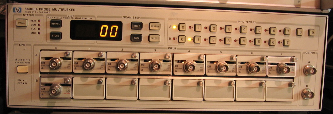
HP 54300A: This piece consists basically of two 8 position coaxial switches. It was designed to take many high impedance probe inputs and put out 50 ohms on the selected pair. I have enough to do 9 probes currently. (OM) Grade: B-
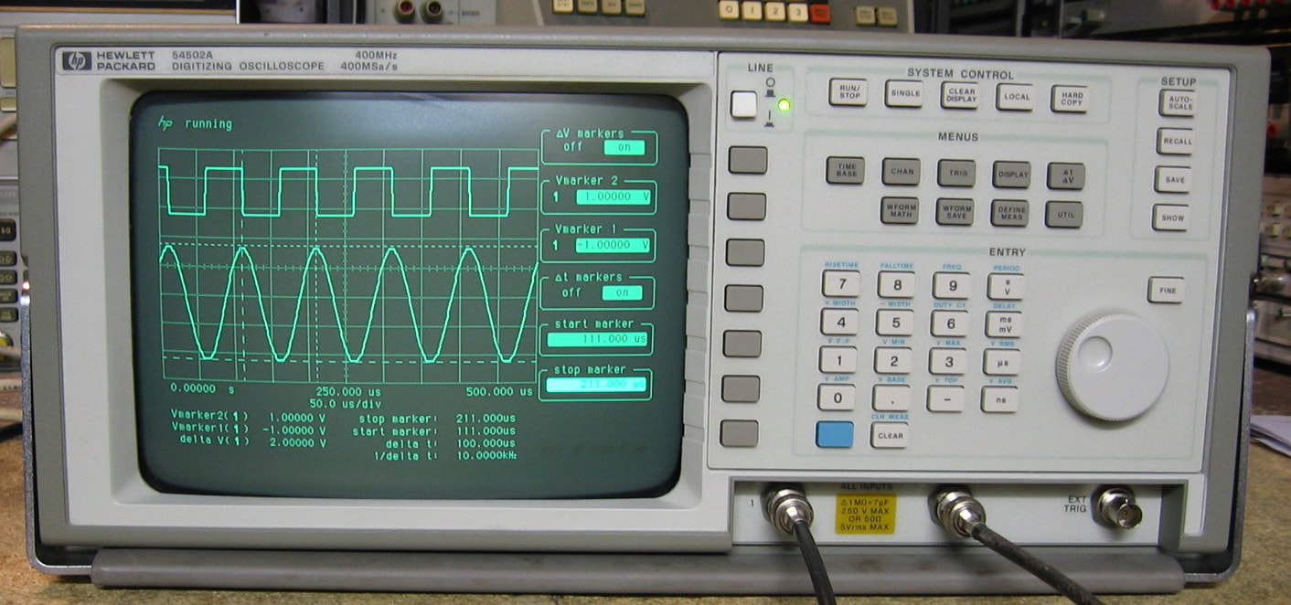
HP 54502A: 400 MHz (400 MS/s sample rate), 2-channel digital oscilloscope. This was the precursor to the much better 54520/40 series of scopes (see entry below) and is an example of when HP was struggling to catch up with Tektronix in the digital oscilloscope market of the early 1990's. It still used the single knob man-machine interface which requires one to push several buttons and then dial the setting (or enter it on the numerical pad). Fortunately, it was right of the end of that single knob era and HP finally concluded that Tektronix and just about every other oscilloscope manufacturer was correct in giving the users what they wanted - dedicated knobs for often used functions like V/div, time/div, position and trigger. Notice the on/off button on the front panel in the picture? The early units used the same back-panel on/off switch as my HP 53310A. I'm glad HP finally did away with that ridiculousness also. The 54502A works fairly well, with minimal lag, but you can tell it only has a 6-bit A/D converter. And in typical HP fashion, it is under-spec-ed, as mine will display a sine wave up to 900 MHz (repetitive sampling mode) at reduced amplitude of course. The inside of my unit, including the enclosed power supply, looks like the day it was manufactured. I was expecting at least a little dirt or dust because the 54502A does have a big fan on the back panel. But it is absolutely mint, so either this scope wasn't used much (also there is minimal screen burn) or someone did a really good job of cleaning. (PDF) Grade: B+
I grabbed this on eBay for $5.50 (+shipping). The seller said it used to work, but now it just makes a clicking noise on startup. Normally I don't like to buy anything with a CRT unless the pictures show it lit up. But I took a chance because I had already worked on a couple of the Boschert power supplies used in these (and other) HP pieces. Upon receipt, I verified the seller's claims, and then pulled the P/S out of my HP 53310A modulation analyzer. Plugged that into the 54502A and the scope worked fine and passed its self-tests. So at least it was worth continuing with the repairs. The Boschert supplies are notorious for leaking electrolytic caps in the secondary and that was certainly the case in the other ones I had worked on. So I pulled 22 capacitors and didn't find a trace of electrolyte anywhere. I then made the normal ohmmeter and diode checks of most of the active components - everything checked out OK. I tested the LED side of the opto-coupler in diode-mode and I was getting the same reading. I've seen this before and I thought nothing of it. I then removed the controller daughterboard with the idea of doing some further testing on it. While it was out, I happened to put my ohmmeter across the LED of the opto-coupler - infinite was the reading. I had been fooled earlier because it was still hooked up to the controller daughterboard. Luckily I had the exact CNY21N opto--coupler in stock, so in it went. I then put back all 22 electrolytics and fired the unit up. Works like a champ! Hopefully the old caps will stay leak-free, but I suspect the next problem will be the DS1230Y NVRAM that holds the cal constants. It has a 1994 date code and could be the original part, meaning it is beyond its expected lifespan. On the other hand, it could have already been replaced at a later date with one having this date code (the Dallas NVRAMs don't actually start consuming internal battery power until they are powered up for the first time). The only way to know is to pull the motherboard out and look at the solder joints underneath the board. No thanks, I'll wait until it dies.
I grabbed this on eBay for $5.50 (+shipping). The seller said it used to work, but now it just makes a clicking noise on startup. Normally I don't like to buy anything with a CRT unless the pictures show it lit up. But I took a chance because I had already worked on a couple of the Boschert power supplies used in these (and other) HP pieces. Upon receipt, I verified the seller's claims, and then pulled the P/S out of my HP 53310A modulation analyzer. Plugged that into the 54502A and the scope worked fine and passed its self-tests. So at least it was worth continuing with the repairs. The Boschert supplies are notorious for leaking electrolytic caps in the secondary and that was certainly the case in the other ones I had worked on. So I pulled 22 capacitors and didn't find a trace of electrolyte anywhere. I then made the normal ohmmeter and diode checks of most of the active components - everything checked out OK. I tested the LED side of the opto-coupler in diode-mode and I was getting the same reading. I've seen this before and I thought nothing of it. I then removed the controller daughterboard with the idea of doing some further testing on it. While it was out, I happened to put my ohmmeter across the LED of the opto-coupler - infinite was the reading. I had been fooled earlier because it was still hooked up to the controller daughterboard. Luckily I had the exact CNY21N opto--coupler in stock, so in it went. I then put back all 22 electrolytics and fired the unit up. Works like a champ! Hopefully the old caps will stay leak-free, but I suspect the next problem will be the DS1230Y NVRAM that holds the cal constants. It has a 1994 date code and could be the original part, meaning it is beyond its expected lifespan. On the other hand, it could have already been replaced at a later date with one having this date code (the Dallas NVRAMs don't actually start consuming internal battery power until they are powered up for the first time). The only way to know is to pull the motherboard out and look at the solder joints underneath the board. No thanks, I'll wait until it dies.
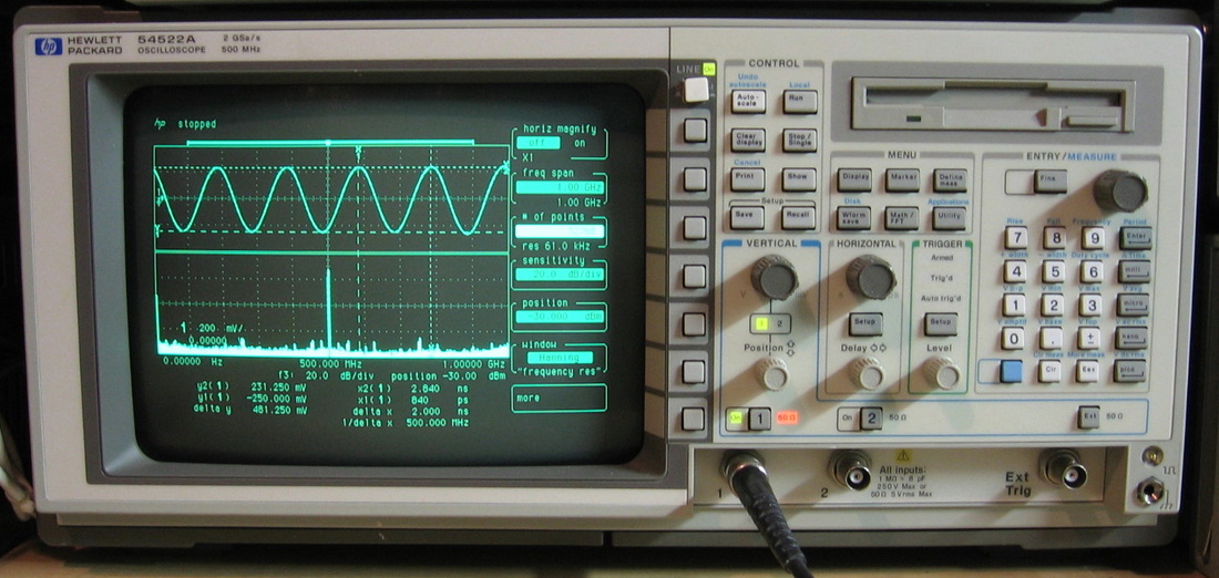
HP 54522A: 500 MHz (2 GS/s sample rate), 2-channel digital oscilloscope. HP introduced their 54520/40 series scopes around 1993 and finally abandoned the single knob man-machine interface of the 5450x and earlier versions (see the entry above for the HP 54112D). These newer scopes have more of the traditional knobs for vertical, horizontal and trigger, yet still retain plenty of soft-menus and keypad/knob entries for those throwbacks to the earlier era. HP made the 54520, 54522, 54540 and 54542 models in both the A (monochrome CRT) and C (color LCD) versions. The fourth digit of the model number refers to the number of channels and the fifth digit is proportional to the sample rate (higher means a higher rate among all channels). So this model is the best 2-channel CRT scope they made. About the same time, HP came out with the 54600 series (see the entry for the HP 83475B which equates to the 54610B). The principal advantage of the newer 54600 series was a smaller package and a much faster waveform/sec update rate. Their best model, the HP 54616B, is analogous to my HP 54522A, both having 500 MHz bandwidths. But HP chose to remove all the math functions, the HPIB, the data interfaces and everything else they could so they could sell them all back as options. The specifications for the 54600 series also aren't quite as good as the 54520/40 series. For instance, the two specs for the 54616B and 54522A are, respectively, 1) min V/div: 2 mV vs. 1 mV; 2) V-accuracy: 2% vs. 1.25%; 3) min H/div: 1 ns vs. 500 ps; 4) H-resolution: 20 ps vs. 10 ps; 5) record length: 5K vs. 32K points. Then again, it was half the price! One feature the 54600 series has is an "auto-store" button which acts like an infinite persistence display in the background. This makes it relatively easy to see, for instance, the modulation envelope of an AM signal - something that the 54522A cannot do. The HP 54600 series is also slightly easier to use in my opinion, but that's because the menus aren't quite as deep. On the other hand, the built-in FFT function in the 54522A is among the best FFT implementation I've seen in an oscilloscope (the picture shows a 500 MHz sinewave input on the top trace and the 1 GHz FFT on the bottom). I really like the 54522A and it definitely will be used a lot. (PDF) Grade: A
I saw this listed on eBay for $250 with offers accepted. The seller claimed that it powered up but the CRT was dark. I know that one can generally replace the CRT with versions found in various other HP scopes or logic analyzers that usually sell for very little, so I wasn't too worried about the seller's claim. On a lark, I offered him $100, figuring it would be rejected. But no, as soon as I entered the offer, the listing accepted it and the scope was mine. Then I looked carefully at the picture which showed indeed a dark CRT, but all of the LEDs on the front panel were lit as though the machine had hung on boot-up. Thinking it might be a P/S problem, I started looking through the various newsgroups, only to find exactly the same symptom described many times. The solution, in every case, was simply to replace the lithium back-up battery (for the RAM that holds the calibration constants). And so it went. It was a royal pain replacing the battery because I had to disconnect everything and pull the main board out. I ran wires to an external battery holder for two AA batteries so I will never have to do it again.
I saw this listed on eBay for $250 with offers accepted. The seller claimed that it powered up but the CRT was dark. I know that one can generally replace the CRT with versions found in various other HP scopes or logic analyzers that usually sell for very little, so I wasn't too worried about the seller's claim. On a lark, I offered him $100, figuring it would be rejected. But no, as soon as I entered the offer, the listing accepted it and the scope was mine. Then I looked carefully at the picture which showed indeed a dark CRT, but all of the LEDs on the front panel were lit as though the machine had hung on boot-up. Thinking it might be a P/S problem, I started looking through the various newsgroups, only to find exactly the same symptom described many times. The solution, in every case, was simply to replace the lithium back-up battery (for the RAM that holds the calibration constants). And so it went. It was a royal pain replacing the battery because I had to disconnect everything and pull the main board out. I ran wires to an external battery holder for two AA batteries so I will never have to do it again.

HP 59401A: Advertised as a GP-IB bus system analyzer, this piece is intended to be hooked up on your GP-IB network for debug and/or monitoring purposes. If you want to tediously strobe 8 bits of GP-IB bus data one word at a time, then this is for you. Need a Ph.D. in GP-IB theory to use properly, regardless of the operating instruction pull-out sheet at the bottom. When I can borrow a nice National Instruments USB-GP-IB adapter from work (with software), who wants to use the 59401A? (OM) Grade: C-
The display had problems. In desperation, touched up the solder joints. Problem fixed.
Postscript: Many years later I turned this piece on and it was completely frozen with essentially no response to the front panel. It took a few days of pointlessly probing around with a logic probe in hopes of finding a bad TTL chip until I stumbled across the problem. The 59401A operates as a state machine and part of the ROM-based "instruction" is the next address to use for the next state. Each clock cycle, this next address is fed into two N8271 latches where it then goes out on the address bus. One of the latches was faulty with the result that the next address was always "000...00," regardless of the ROM contents, hence the piece simply hung. Fortunately, I found a set of used N8271 chips on eBay and that did the trick.
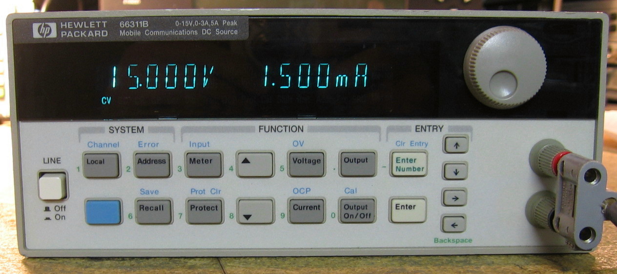
HP 66311B: Mobile Communications DC Source. In other words, a power supply! Although it is basically a 15V, 3A supply, it is intended to test devices such as phones or digital radios that have rapidly changing current draws. To support this, the 66311B is able to measure V and I very rapidly and display the basic statistics. So think of it as a power supply with a scaled-down DVM inside. HP/Agilent/Keysight is still producing these units (as of 2017) and they come in a variety of model numbers/configurations. They also act as a two-quadrant device in that they will sink current (however, the sinking capability is not programmable). The user interface is a bit cumbersome and it takes quite a few button presses to navigate your way through all of the menus. Also, the fan inside is L-O-U-D. Spec-wise, it is OK, nothing to write home about. A cute power supply, but certainly not worth the $2,300 street price in my opinion. (PDF) Grade: B+
Advertised as basically stuck with -0.25A displayed and Error 4 shown, I took a chance at $80 because the listing photo showed that the sense connections on the back panel were missing. But alas, that was not the problem. I think the seller didn't fully understand how to set the controls, because the output was fine. However, the current shown on the display was about 0.25A low, consistent with his observation of -0.25A when the output was off. That sounded like a calibration EEPROM problem to me, especially given the fact that Error 4 meant that the part of the EEPROM holding the four saved states was also failing its checksum. So I had the unit save its state four times and that cleared out Error 4. I then marched through the cal procedure which took several tries since the existing cal constants were so screwed up, I was getting "out of range" errors during the procedure. But eventually everything went smoothly and the unit is now working correctly. Finally, I added to banana plugs to the front panel and ran wires back to the output terminal block on the rear panel. The sense lines run to these banana plugs which should be sufficient for most uses. If not, I can very easily disconnect my sense wires at the rear and run independent senses.
Advertised as basically stuck with -0.25A displayed and Error 4 shown, I took a chance at $80 because the listing photo showed that the sense connections on the back panel were missing. But alas, that was not the problem. I think the seller didn't fully understand how to set the controls, because the output was fine. However, the current shown on the display was about 0.25A low, consistent with his observation of -0.25A when the output was off. That sounded like a calibration EEPROM problem to me, especially given the fact that Error 4 meant that the part of the EEPROM holding the four saved states was also failing its checksum. So I had the unit save its state four times and that cleared out Error 4. I then marched through the cal procedure which took several tries since the existing cal constants were so screwed up, I was getting "out of range" errors during the procedure. But eventually everything went smoothly and the unit is now working correctly. Finally, I added to banana plugs to the front panel and ran wires back to the output terminal block on the rear panel. The sense lines run to these banana plugs which should be sufficient for most uses. If not, I can very easily disconnect my sense wires at the rear and run independent senses.
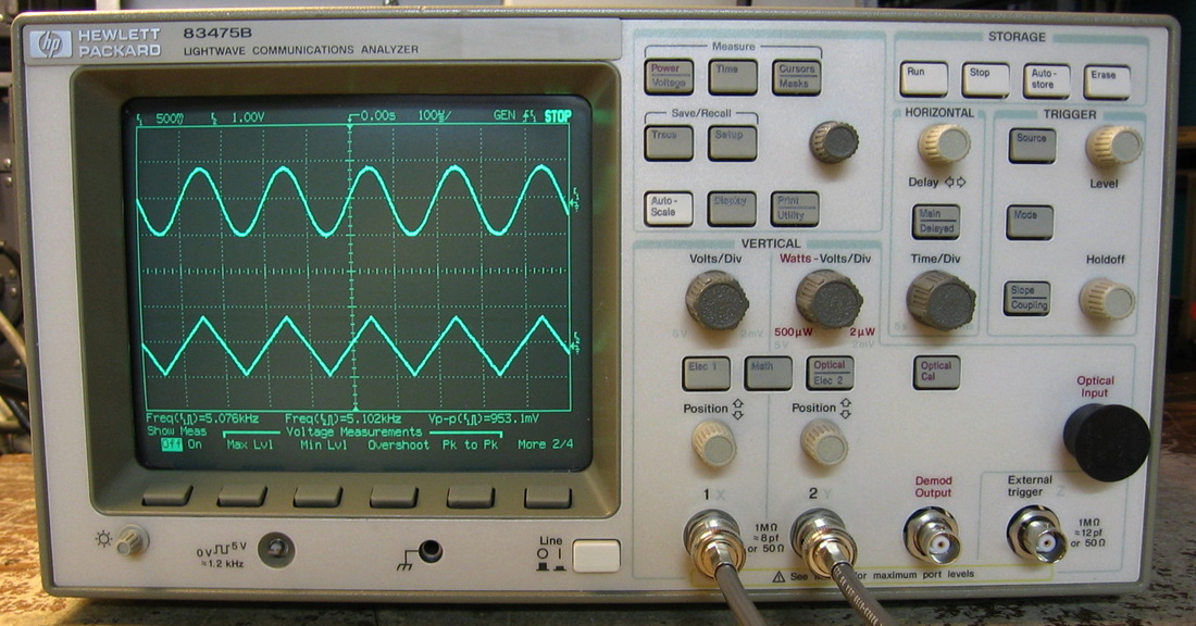
HP 83475B: This scope is sold as a Lightwave Communications Analyzer. When I saw it sitting on eBay for $99 with no bids, I was highly amused. Equipment like this rarely sells on eBay - potential buyer's eyes just glaze over when they see anything "optical." But what apparently I only know is that the 83475B is really an HP 54610B oscilloscope with an additional optical detector board. Moreover, the 54610B usually sells in the $500-$1,000 price range (the last two sold on eBay for $875 and $1,000). So $99 was a real bargain, assuming it works. Which it does quite nicely! The scope is rated to 500 MHz and has an effective sampling rate for repetitive signals of >10 GHz (random sampling), but only a 20 MHz single shot capability. Mine has Options 12 and 51. One of these options is GPIB; I have no idea what the other option is since I can't find the 83475B listed in any old HP catalog, but I think it is some variant of an optical bandpass filter. HP was never known for producing great scopes and this 1995 model was in the era where manufacturers were switching from analog to digital designs and hadn't worked out all the bugs. Nevertheless, I am pleasantly surprised with how well this scope works. My only complaint is the rather flimsy plastic case which won't take the weight of six other pieces sitting on top of it. (PDF) Grade: A-
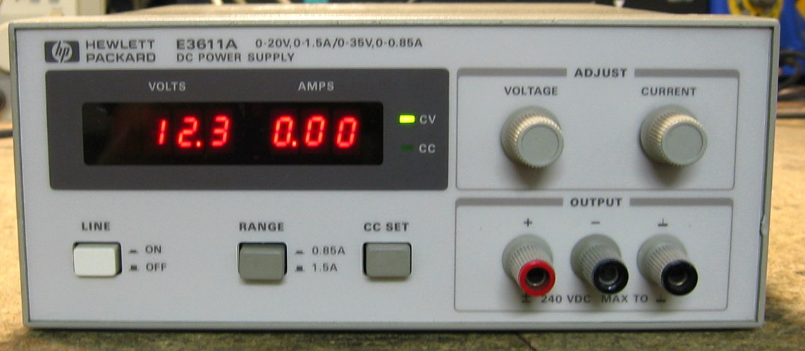
HP E3611A: Basic, no frills 30 watt linear power supply in two ranges: 0 - 20V @ 1.5A or 0 - 35V @ 0.85A. There are a bunch of HP E361x models to choose from. They were manufactured in the early 1990s when HP was in their "let's build stuff cheap" phase. While the design and electrical components are fine, the mechanical design really shows how cheaply they are made (albeit it must have cut down on assembly time). For instance, the boards snap into the plastic case and the case itself snaps together - there isn't a single screw anywhere to be found. Certainly not for precision work, this supply was only $300 in 1997 and is designed for general lab use. It does have a current limit switch on the front panel that eliminates the need to short the output and that's a plus in my book. (PDF) Grade: B
Advertised as not accurately displaying output, the eBay photo showed the unit with both the CV and CC LEDs lit. Well, you can't have a power supply doing constant voltage and constant current simultaneously, so obviously the E3611A was broken. But the price was right - $20 - and I needed something to fix. Upon receipt, the output voltage was changing as I turned the front panel pot, but the display was nonsense as the seller indicated. When I snapped open the covers, there was a board full of seeping electrolyte and two 330 uF capacitors that were obviously puffy. I removed all the electrolytics and it was only those two that were toast. The leaking caps were Nichicons and I was somewhat surprised that these failed given that Nichicon is a top-rated brand. However, they are about 1/4-inch away from the main transformer which can get quite warm. Probably a minor thermal design fault on HP's part. Cleaned everything up, replaced the caps with 470 uF caps that I had in the junkbox, and the unit responded correctly. The only other fatality was a sheared off negative output banana jack on the front panel. Again, a brief consultation with my junkbox remedied that. There are a couple of broken fins on the rear panel heatsink, but that is a non-issue given only the 30 watt capability of this supply
Postscript: Saw a recent YouTube video from "Poor Man's Electronic Bench" who was fixing his similar E3612A. He suggests that the failure of the electrolytic capacitors is not really a heat issue as I surmised, but rather endemic to the capacitor's ability to deal with the input ripple. I will defer to his expertise. I've seen several pieces with electrolytics that get too warm (for instance, the early Keithley 2000 DMMs) because of their proximity to other parts, and I merely thought the E3611A was yet another example. But wait - I turned on the piece to see if the transformer does actually get warm and noticed that the E3611A's display was gyrating (although the output was correct) and showing CV and CC both lit. Opened up the unit and found yet another Nichicon electrolytic capacitor (4700 uF//25 V) leaking all over the board. So that's three of these Nichicons that have leaked. Don't know definitively if HP got a bad batch, it is a thermal issue, or a design fault, but I've knocked down the E3611A's grade down a bit. So buyer beware if you are buying one of the E361X units. On the plus side, the fix is trivial. A word to the wise: if you have leaking electrolyte, do yourself a favor and pull out the main board, scrub it with detergent, gently rinse, and let it air dry. Otherwise you may find (as did I) that the unit will behave erratically even after the caps have been replaced.
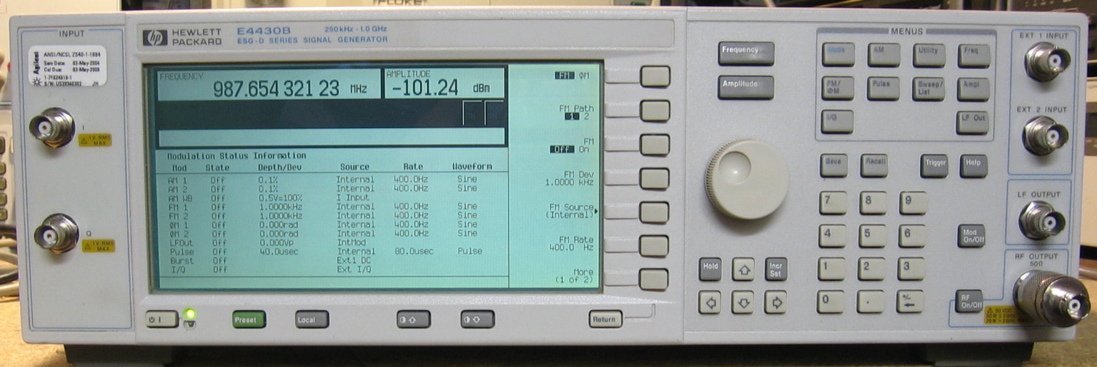
HP E4430B: RF Signal Generator to 1 GHz. HP made the E4430B, E4431B, E4432B and E4433B, with upper limits of 1, 2, 3, and 4 GHz respectively. I have the lowest frequency variant, but my guess is that the hardware is all the same and a software hack would enable it up to 4 GHz. My unit also has some digital I/Q capability, but HP made an analog-only version too. And to be even more confusing, all of these units had tons of options. Mine appears to be a simple base unit with no options. The specs are too numerous to list, so I won't, but a careful reading of the datasheet reveals they aren't particularly good. Because of all the available options, this is more of a multi-purpose signal generator than one with particularly high fidelity (like my HP 8642B). One curious observation is that the E4430B amplitude is rated from +13 to -136 dBm but the front panel allows you to dial in as high as +20 dBm. The result is an output with tons of harmonics since the thing is obviously being overdriven. Can't be too good for the marginal step attenuator, can it? I don't know if this was a firmware bug or not. The E4430B is one of my youngest pieces and would look at home on the lab bench even today, 20 years later. (PDF) Grade: A-
When I got this piece, it fired up fine and the basic functions, menus and display seemed OK. But then I hooked it up to a spectrum analyzer and saw that the output was about 16 dB less than what I had dialed in. However, once I got down to a -95 dBm setting, the amplitudes were fine down to -135 dBm. Figuring it was likely the electronic attenuator, I hooked the spectrum analyzer up to the cable coming out of the RF section going to the input of the attenuator. I got full amplitude and the levels marched down correctly for about 5 dB, then went back to the start - this is consistent with the attenuator being a 5 dB/step model. So that proved that the culprit was the attenuator, not some funky ALC problem in the RF generator circuitry. I pulled out the attenuator and dissected it. Briefly hooking it back to the control lines, I verified that the command bits were being decoded correctly as a function of the amplitude setting on the front panel. The actual attenuator (PIN diode???) was in a sealed box and there really was nothing I could do about that. So I reassembled everything and turned on the signal generator to make sure I didn't cause any additional damage. As if by magic, the E4430B 's amplitude was now perfectly correct. I don't have any real explanation other than perhaps there was a marginal solder joint on the board inside the attenuator and my removal/installation torqued things down slightly differently than before and corrected the joint. Only a guess. I hope it stays this way.
Postscript: A couple of days later, I came across a YouTube video from user Feedback.Loop who was fixing his HP E4421B signal generator. That model uses exactly the same electronic attenuator as my E4430B and he was getting outputs that were also 16 dB too low. He dissected his unit, concluded there wasn't much that could be done if it needed repair, and put it back together, only to find that it now worked flawlessly - just like mine! Pretty amusing. There's still no explanation though.
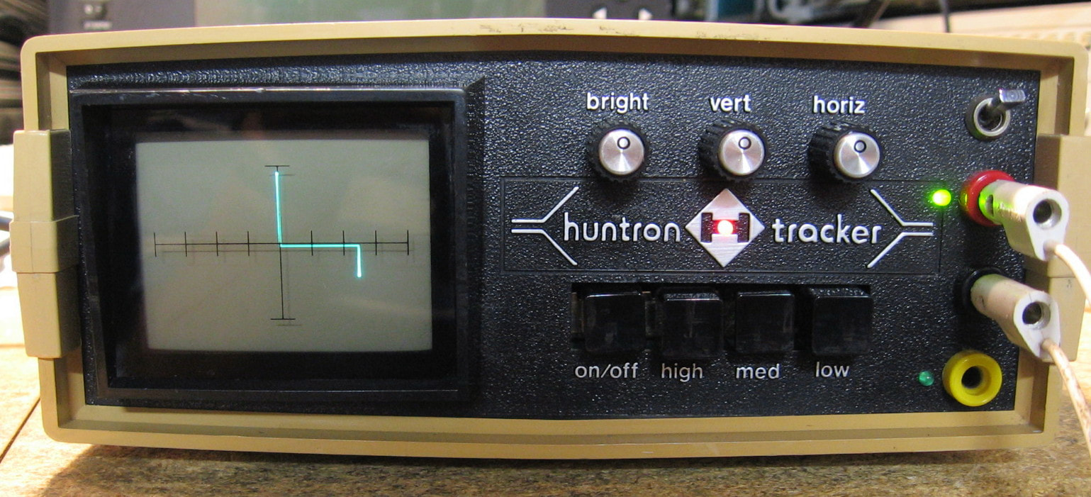
Huntron Tracker 1005B: This is a poor man's curve tracer. Essentially what it does is plot V (x-axis) vs I (y-axis) using an 80 Hz sine wave source. The display is kind of backwards in that the response to the positive cycle of the stimulating wave is on the negative x-axis and the negative cycle is on the positive x-axis. It was built by Huntron as an analog component tester with the idea that different components will yield different curves on the display. For instance, a resistor will be a straight line, a capacitor will be an ellipse, a diode will have an "L" shape, a Zener will have a rotated "Z" shape (shown in the photo), etc. Has three different source ranges (low, med, high) which again seems backwards to me, as the high range is the one with the largest source resistance (hence lowest applied current). Huntron also included a "B" input and a toggle switch, that when set to the middle, will alternate the readings between the "A" and "B" inputs. Hence, you can easily debug a circuit board if you have a known good one sitting next to it. The basis for this design is the well known "Octopus" circuit (google it) developed decades ago and requiring about $1 worth of parts and an oscilloscope (in x-y mode). All Huntron really did was give the user a few more parameter selections and put a small oscilloscope inside. These things are still made today, albeit with a much fancier design, and seem to have somewhat of a cult following given the prices they command on eBay. Not a real curve tracer, but more of an analog signature analyzer, much like my HP 5005B and 5006A are digital signature analyzers. (PDF) Grade: B+
I : Instek, Iwatsu

Instek GFG-8020H: Generic 2 MHz function generator still being sold new today for about $200. The usual design based upon charging/discharging a capacitor to get a triangle waveform, and then deriving the sine and square waveforms from that. Has a VCF input, variable DC offset, variable symmetry, invert function and a separate jack/control to output TTL or CMOS pulses. Will do 20 Vp-p open circuit and has a square wave rise time of 125 nsec which makes the 2 MHz square waves not too crisp. Since there is no hope of calibrating the tuning dial, Instek threw in a digital counter to display the frequency on the front panel. Pretty ordinary and boring, but I'll bump up the grade a bit because the build quality is quite nice (actually it is outstanding for the Chinese). (PDF) Grade: B+
An e-Bay seller was offering a single buy of two of these, listed as both non-working, for $58 + shipping, so a pal of mine and I split the purchase and we each picked our unit at random out of the box. The one I got rattled when I shook it and the culprit was a 47 ohm resistor that was bouncing around the insides. Even without the schematic, it was pretty clear that the resistor was one of two 47 ohm jobs that hang off the positive and negative voltage rails into the collectors of the NPN-PNP push-pull output amplifier. The resistor still measured 47 ohms so I soldered it back in and powered the unit on. In less than 5 seconds, the resistor had already heated up past 150 degrees. So it turned out, it must have actually heated up enough to melt the solder joints and fall out (the main board sits upside down in usual use). My guess was that one of the 2N2219A/2N2905A amplifier transistors had shorted, so I pulled them both out and, sure enough, a C-E short on the 2N2905A PNP. I found a 2N2905A on one of my junk boards, threw it in and fired the thing up. Everything looked fine with an unterminated BNC cable going into the scope. But when I terminated the cable with 50 ohms at the scope, I lost all output. Made no sense to me until I turned the unit off and measured the resistance across the output jack. Expecting 50 ohms, I was a bit surprised to measure 400K. Turns out that there is an ordinary 200 ma glass fuse going to the output jack and the fuse measured 400K. Didn't know fuses could partially blow. Anyway, a new fuse, a couple of 100 ohm resistors that also measured OK but looked burned and we will call it a day on this one.
An e-Bay seller was offering a single buy of two of these, listed as both non-working, for $58 + shipping, so a pal of mine and I split the purchase and we each picked our unit at random out of the box. The one I got rattled when I shook it and the culprit was a 47 ohm resistor that was bouncing around the insides. Even without the schematic, it was pretty clear that the resistor was one of two 47 ohm jobs that hang off the positive and negative voltage rails into the collectors of the NPN-PNP push-pull output amplifier. The resistor still measured 47 ohms so I soldered it back in and powered the unit on. In less than 5 seconds, the resistor had already heated up past 150 degrees. So it turned out, it must have actually heated up enough to melt the solder joints and fall out (the main board sits upside down in usual use). My guess was that one of the 2N2219A/2N2905A amplifier transistors had shorted, so I pulled them both out and, sure enough, a C-E short on the 2N2905A PNP. I found a 2N2905A on one of my junk boards, threw it in and fired the thing up. Everything looked fine with an unterminated BNC cable going into the scope. But when I terminated the cable with 50 ohms at the scope, I lost all output. Made no sense to me until I turned the unit off and measured the resistance across the output jack. Expecting 50 ohms, I was a bit surprised to measure 400K. Turns out that there is an ordinary 200 ma glass fuse going to the output jack and the fuse measured 400K. Didn't know fuses could partially blow. Anyway, a new fuse, a couple of 100 ohm resistors that also measured OK but looked burned and we will call it a day on this one.
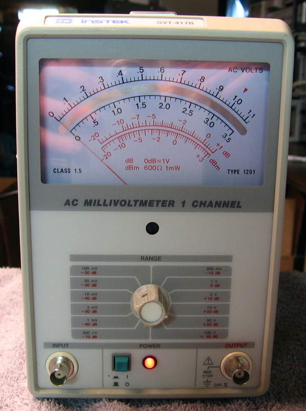
Instek GVT-417B: The Instek equivalent of the HP400 series AC voltmeters. Basically the same specs, but the meter has the nice feature of full scale being not quite all the way. No service manual available, so I turned the pots inside until it was "calibrated." (---) Grade: B+
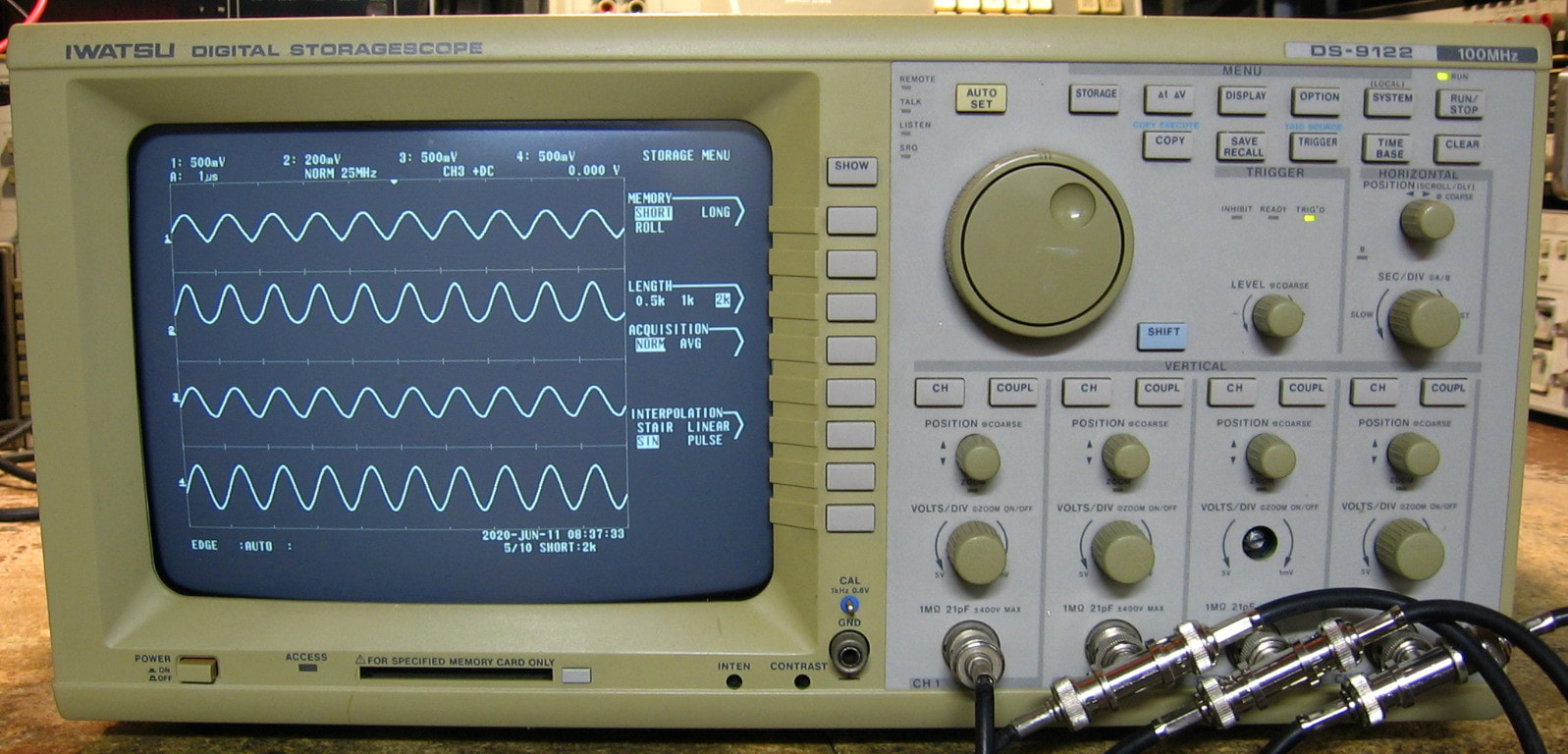
Iwatsu DS-9122: 4-channel, 100 MHz digital oscilloscope. Iwatsu is a reputable Japanese test equipment brand that is pretty much neglected here in the USA. The DS-9122 appears to have a bandwidth of 100 MHz with a base sampling rate of 25 MHz - equivalent time sampling, which was the rage back in 1993 when this unit was built, is employed for high frequencies. On the positive side, the CRT is really bright and crisp. On the negative side, the controls and menus seem a bit out of step with what I am used to in an oscilloscope. One thing that is useful is the built-in thermal printer which captures a screenshot and works very nicely. The build quality is first rate and the components are all name-brand and high quality. Certainly the DS-9122 was not built to a particular low price point. However, if I compare this 1993-built scope to, say, my Tektronix TDS520 built around the same time, the Tektronix is way ahead in features, performance and update rate. The Japanese may be very good at production, but they clearly did not innovate with this model. And it is also very annoying that I can find virtually no information about this scope. Forget about manuals! (---) Grade: B
I bought this for only $30 and wasn't expecting too much. The seller said it was working fine, then started to randomly reboot, then finally went dead. So I figured on a switching P/S repair job. But when I got it, the piece powered up and stayed that way for about one hour before it clicked and rebooted. Moreover, the volts/div were way out of calibration and the self-cal routine failed with errors (and didn't change anything). I opened the unit up and pulled out the P/S. It is a two board job and is extremely complicated, but nothing seemed out of order. Then I started inspected the analog and digital boards only to find little puddles of electrolyte and corroded pads near the SMT electrolytic caps. Aha - the Iwatsu suffers from the same diseases as my Tek TDS520. I decided to re-cap the unit and it turns out that of the 41 caps I replaced, 39 of them tested bad (only a few nF at best). The boards were all scrubbed clean numerous times as was also the case with the Tek scope. But all is not well, for the scope still has multiple faults: 1) the baseline for channel #2 will not go negative with the vertical position knob and the amplitude is about half of what it should be; 2) the memory for channel #3 is faulty and produces random glitches on the captured waveform; 3) channel#4 has a ~300 kHz noise train (a few mV) superimposed on the signal; 4) the unit will not self-calibrate. In other words, it is in pretty bad shape. However, it does work as a basic scope as long as you don't try to measure the signal amplitudes. Let me also add that I have never seen so many devices on the analog boards as are in this scope. From the input BNC jack, a channel goes through a few relays and a preamplifier - the same as in most scopes. Then there must be 250 assorted resistors, caps, transistors, op-amps and multiplexers before the signal gets to the digitizer. It absolutely blows my mind that Iwatsu made it so complicated. At this point, I pretty much abandoned any further repairs unless I am ever able to locate a schematic.
Postscript: A week or so of head banging and here's what happened. For problem #1 (channel #2 baseline and amplitude), the signals coming out of the front-end amplifiers seemed fine, but as it nears the digitizer, one of the differential pairs was obviously wrong. There is an IMX5 dual NPN UHF transistor that first processes the pair and one side tested bad, so the IMX5 was replaced and channel #2 was cured. For problem #2 (channel #3 memory), each channel contains two memory sticks, A and B, each having two 8Kx8 SRAMs. By swapping memory sticks, I proved that channel #3's B-stick was the culprit (the fault followed wherever I put the stick). I obtained two equivalent SRAMs and replaced the chips on the B-stick. Led me add that these are SOJ parts and are a real bear to hand solder with an iron. After buzzing the solder connections, and finding the few that I had done improperly, I installed the memory and found absolutely no change to my problem. At this point, I pulled out the stick, and rather than buzz the connections to the nearest via or to the similarly used pin on the other memory, I buzzed the chip leads back to the connectors on the stick, only to find two that were open. Bottom line: the leaking electrolyte (from the other side of the board) got underneath the solder mask and ate away two traces. Impossible to see even under magnification, but an ohmmeter doesn't lie! After I jumpered over the severed traces, my memory problems with channel #3 were fixed. For problem #3 (300 kHz noise), I again isolated the problem to the front-end attenuator (not any of the amplifiers) by switching channels are watching the fault follow. I pulled out the faulty attenuator and another channel's known good attenuator and started blindly comparing resistances. This led me to Q9 (an FET) where I was getting about 50K on the good one and a few Megs on the bad. By tracing the circuit, I found a cracked SMT resistor joint. Touched that up and the 300 kHz noise was gone. For problem #4, the self-cal would abort midway with an error message and no cal constants would be changed. Each channels attenutor/preamp chain has eight caps or resistors (and I don't know what specifically each one does). But by trial and error, I was able to make small adjustments and retry the self-cal. Eventually, the self-cal passed and also passed repeatedly after that. So now, the 9122 basically works, although it is not perfect: 1) channel #3 doesn't seem to want to properly adjust the square wave compensation, and 2) channel #1 occasionally moves vertically about 1/4 division at random. But given the fact that every time I start pulling boards and manipulate things, something else seems to malfunction, I think I will call success and stop right here. Some day, maybe an obvious fault will develop.
Postscript^2: I tried once again (in vain) to correct the lack of frequency response on channel #3 I reflowed one SMT transistor (Q3) where it seemed that my input square wave was turning into a triangular wave. This actually worked! While I was patting myself on the back, I noticed that the baseline for channel #3 was now randomly fluctuating. Some more board cleaning didn't help so I hit the area with a heat gun. Soon thereafter, the baseline stabilized, but now I was back to the lack of bandwidth again! All I can conclude is that there must have been some serious damage to the (multi-layer) boards from the leaking electrolytic caps and my chances of fixing that are negligible
Postscript^3: "Never give up," someone famous once said. Turns out that now channel #1 and channel #3 have lost their bandwidth. Moreover, channel #3 will recover the bandwidth if I give the boards a little heat, but then the baseline randomly jumps all over the place. Moreover, none of the four baselines ever really stay stable - every time I turn the scope on, they are in a different place and I have to run the cal procedure. I already replaced the four IMX5 dual-NPNs that are the first amplifier the signals all see coming out of the attenuator/preamps. The next transistors in the signal path are 2SC3356, ultra-high (7 GHz!) amplifier NPNs. On channels #1 and #3 that have lost their bandwidths, the collector of those two transistors is where my input square wave turns into a triangular wave. An ohmmeter showed the E-B resistance as 55 ohms and 8 ohms on these two (reading was the same in both directions). So I ordered enough 2SC3356s to replace them on all four channels. After I did that, the bandwidths were all fine, the baselines were all fine, and the scope seems to now, finally, work fine. Hooray!
Postscript^4: Every couple of months, I turn this thing on. Sometimes it works fine, sometimes some of the channels suffer gain problems. Finally in desperation, I removed all of the female connectors on the acquisition motherboard for the four preamp daughterboards, after noticing that pressing on the boards often changes the displayed amplitude, and permanently soldered the daughterboards. Now, pressing on the boards doesn't alter the waveforms and maybe finally (?) I am done with this piece. I hope so because removing a daughterboard is not something I'm looking forward to.
K : Kaiweets, Kay, Keithley, Kikusui, Klein, Krohn-Hite
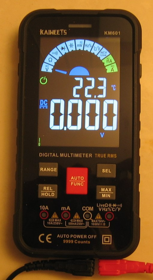
Kaiweets KM601: 4-1/2 digit DMM. This is a cute DMM with mediocre specifications that will do DCV, ACV, DCI, ACI, ohms, frequency, capacitance, diode, temperature and continuity. The best spec is DCV at +/-0.5% + 3 counts which seems like the standard spec for most DMM's cheaper than $50. Its claim to fame is that it defaults to an automatic mode which will determine whether your input is volts or ohms. Sounds like a recipe for disaster and I always manually select the function I want. It has a few niceties like a flashlight and a dual display (ACV + frequency, or frequency + duty cycle). The build quality seems fine although the test leads are pretty junky. One can find DMMs with similar specs at lower prices, so the KM601 is slightly pricey. Operates on 3 AAA-alkalines, but I have no idea how long they typically will last. The user interface takes a bit of getting used to and it is somewhat annoying to keep pressing the function button to change modes over and over again. My unit ($43.50 + free shipping) reads about 0.25% low on DCV and ACV (within spec); the other functions are much closer to nominal and well exceed the specs. The biggest selling point, in my opinion, is the size - small enough to put in your pocket. And for quickly checking things around the house (batteries, AC adapters, energized outlets, cable continuity, etc.), it is perfect. Let's just say I won't be using the KM601 to do the performance verification on my Fluke 5440B voltage calibrator! (PDF) Grade: B+
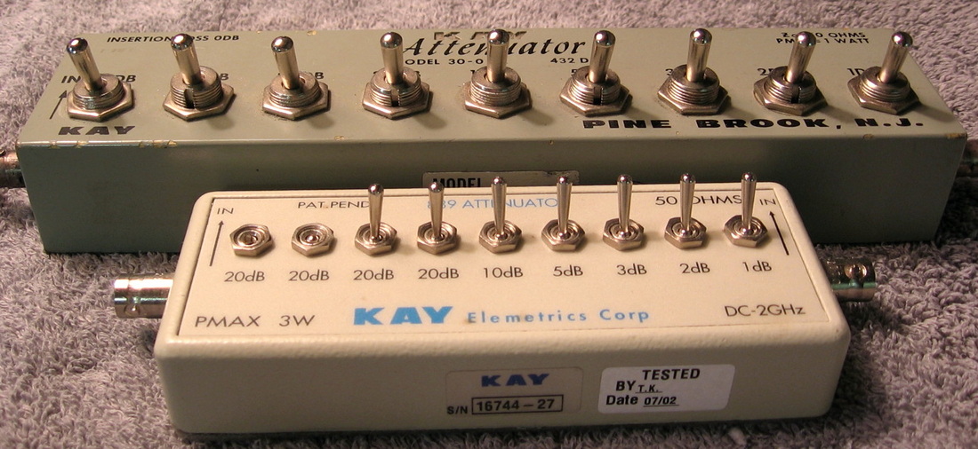
Kay Attenuators: Old and new. The new one has the special "no first two switches" option. (PDF) Grade: B
I rebuilt both of them, but did not want to spend money for new switches for the smaller one.
I rebuilt both of them, but did not want to spend money for new switches for the smaller one.
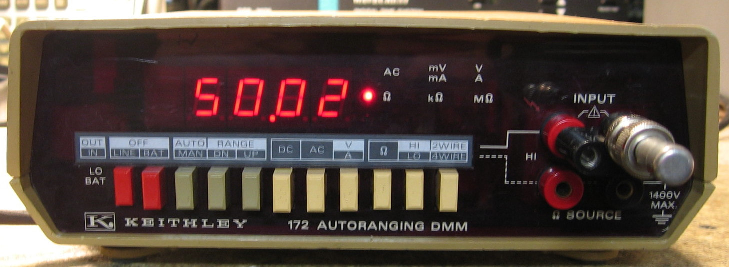
Keithley 172: 4-1/2 digit autoranging DMM. This came in a buy of 5 Keithley picoammeters, but instead of one of the ammeters, I got this. Does DCV, ACV, DCI, ACI and ohms (hi and lo ranges). Accuracy is 0.01% for DC, 0.15% for AC, 0.03% for ohms and about 0.25% for current, making this piece only so-so. It offers a battery option, but thank God mine didn't have it (with the usual leaking batteries). (PDF) Grade: B
When I took this piece out of the box, it looked as though the thing had been standing up on end for years with a leaking battery on top. The input jacks were full of corrosion and the pushbutton switches were pretty well frozen. Some lubricant got the thing mostly back to working order with the exception of the ohms function which was putting out too much current (and thus overloading on the higher ranges). The culprit was an NPN transistor hanging off the ohms line as a protection device. Obviously, it did its thing and while protecting the meter, it fried itself into a short. A new transistor fixed the ohms function. While calibrating the piece, I noticed a little non-reproducibility on the upper DC ranges, so I desoldered the main range relay and gave it a burnishing. Seems fine now, but pieces of this vintage are mechanically nearing their end of life.
When I took this piece out of the box, it looked as though the thing had been standing up on end for years with a leaking battery on top. The input jacks were full of corrosion and the pushbutton switches were pretty well frozen. Some lubricant got the thing mostly back to working order with the exception of the ohms function which was putting out too much current (and thus overloading on the higher ranges). The culprit was an NPN transistor hanging off the ohms line as a protection device. Obviously, it did its thing and while protecting the meter, it fried itself into a short. A new transistor fixed the ohms function. While calibrating the piece, I noticed a little non-reproducibility on the upper DC ranges, so I desoldered the main range relay and gave it a burnishing. Seems fine now, but pieces of this vintage are mechanically nearing their end of life.
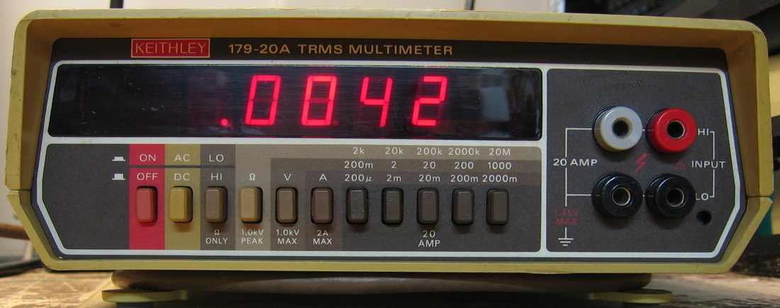
Keithley 179-20A: Pretty basic 4-1/2 digit DMM. I guess the -20A refers to the 20A option. Keithley always made very high-end stuff, much too expensive for my meager budget. So this was my chance to own one of their pieces as it was in a single buy with the Fluke 8050As and Fluke 8800A. The build quality is pretty average, but the thing seems really accurate. (PDF) Grade: B-
Nothing was really wrong with this except dirty switches and a blown internal fuse. It was very easy to calibrate since the inner cover plate has the step number, the instrument setting, the calibration voltage and the expected reading all printed on it with arrows pointing to all the adjustment pots.
Nothing was really wrong with this except dirty switches and a blown internal fuse. It was very easy to calibrate since the inner cover plate has the step number, the instrument setting, the calibration voltage and the expected reading all printed on it with arrows pointing to all the adjustment pots.
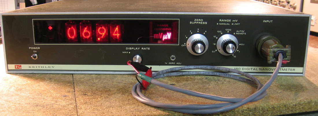
Keithley 180: Digital Nanovoltmeter. 100 uV to 1 V full-scale in five ranges with accuracy of about 0.05%. Resolution is down to 10 nV which is the reason I coughed up $50 for the thing. A throwback to an earlier era with nixie tubes, although my unit was built around 1980 and should have had LEDs. It is fairly easy to use and only requires you to short the leads and adjust the zero-suppress control prior to making a measurement (on the lower three ranges). The manual shows that the noise is about 10 nV, but I'm seeing much more of course, because I don't have proper low-thermal contacts, a temperature-controlled oven, RF shielded environment, complete lack of ground loops, proper guarding and everything else one needs to do it perfectly. My thought was to use this as a null meter because most of my DMMs have trouble reading below 1 uV. But the 30 Mohm input impedance is probably insufficient and I think I will use the Fluke 887A differential voltmeter instead. Also, the 180 has a very long time constant on the lowest range, something like 30-40 seconds to get a stable reading (assuming your source stays stable for 30-40 seconds which is highly dubious). Oh, and you think this thing isn't sensitive? I unscrewed the input cable and shorted the two pins on the unit with a 1" piece of wire. Adjusted the zero-suppress for 00.00 and then simply pointed a low-power flashlight at the wire from one foot away. The reading went up 200 nV. (PDF) Grade: B+
Advertised by the seller as "does not power on, being sold as is for parts/repair," it actually was turning on. However, there was a distinct absence of 5 Vdc and since all of the display drivers/logic are TTL chips, the display was blank. The culprit was a 7805 regulator. However, the 7805 had a strange failure mode (verified on the bench with an external P/S) where it was fine until the input voltage was 10.5 V. At that point, it simply gave up and produced zero output. And as luck would have it, the voltage coming out of the rectifier/filter in the Keithley was 10.6 V!
While a new 7805 got the 180 up and running, I still needed to address the input connector which is a "special Keithley low-thermal" Cannon 16-11. Mouser had an Amphenol plug that fit for $30 so I went with that. The only other problem was that I was running out of adjustment room on the pot that sets the zero point at low ranges. I padded a resistor in the input circuit which solved that problem. Note that this unit, although only drawing about 25 watts, runs extremely hot at the 5V regulator - I measured the heat sink at 160 deg F. That's probably why the 7805 failed. And there are a few electrolytic capacitors within 1/4" of the heat sink that probably aren't long for this world either.
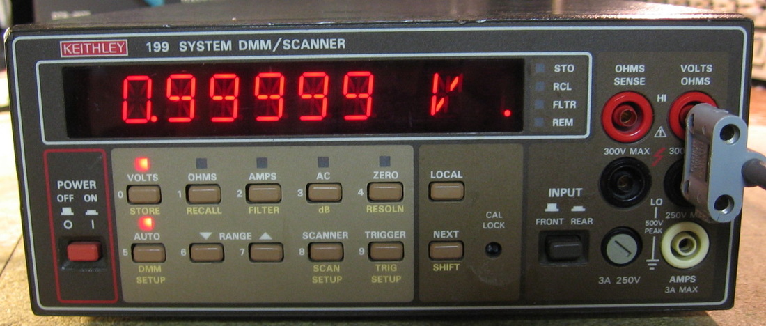
Keithley 199: Basic 5-1/2 digit DMM. Pretty vanilla, but does DCV, ACV, DCI, ACI and ohms. Best case 1 year DCV accuracy is about 0.007%. Extremely boring with only moderate build quality. (PDF) Grade: B+
Advertised by the seller as working, he was obviously lying. Although it seemed OK on current and AC voltage, the DC was way off. On the 300 mV range, a shorted input produced 275mV and the thing would over-range with so much as 1 mV of supplied voltage. The 3V and 30V ranges were inaccurate and would not read any higher than about 17V. And the 300V range read 000.000 and was unresponsive to any inputs. The ohms was equally as screwed up with almost random readings to any resistor. The fact that AC and I worked, but DC and ohms didn't, pointed to a problem with the input ranging, not the A/D. The entire machine is controlled by four daisy-chained CD4094 8-bit shift/store registers going to FET switches and the service manual shows which switches should be open or closed. Starting out with the faulty 300 mVDC range, I immediately found one switch that was being commanded to close, but not listed in the service manual's table as being closed for that range. Looking at the schematic, it didn't much affect anything since the entire surrounding circuit was isolated from the rest of the circuitry through a properly open FET. But that led me on a wild-goose chase since I suspected one or more of the 4094's was bad. I switched two of the four and it had absolutely no effect. So that left me scratching my head until I got the bright idea to check the input impedance of the unit. On all the DCV ranges, the input impedance was 1.37K ohms - clearly wrong! It didn't take me long to find a shorted reed relay that was keeping the ohms circuitry on-line along with the DC circuitry. I pulled the relay and things started to improve on the DCV side. However, the 300V range was still reading 000.000 for all input voltages and the 300mV range was still reading 275 mV with a shorted input. Finally it dawned on me that the previous idiot owner may have tried to calibrate this thing without realizing the ohms relay was shorted. The calibration is done via stored software constants, so I re-calibrated it and the DC worked flawlessly on all ranges. I found a replacement reed relay in my parts bin and installed that, but the ohms was still screwed up. The culprit was a protection transistor hung off of the ohms line that measured 70 ohms C-E. I clipped that out and now ohms works fine (after I did the requisite calibration). My guess is that the idiot had the 199 in ohms mode and then put several hundred volts across it.
Advertised by the seller as working, he was obviously lying. Although it seemed OK on current and AC voltage, the DC was way off. On the 300 mV range, a shorted input produced 275mV and the thing would over-range with so much as 1 mV of supplied voltage. The 3V and 30V ranges were inaccurate and would not read any higher than about 17V. And the 300V range read 000.000 and was unresponsive to any inputs. The ohms was equally as screwed up with almost random readings to any resistor. The fact that AC and I worked, but DC and ohms didn't, pointed to a problem with the input ranging, not the A/D. The entire machine is controlled by four daisy-chained CD4094 8-bit shift/store registers going to FET switches and the service manual shows which switches should be open or closed. Starting out with the faulty 300 mVDC range, I immediately found one switch that was being commanded to close, but not listed in the service manual's table as being closed for that range. Looking at the schematic, it didn't much affect anything since the entire surrounding circuit was isolated from the rest of the circuitry through a properly open FET. But that led me on a wild-goose chase since I suspected one or more of the 4094's was bad. I switched two of the four and it had absolutely no effect. So that left me scratching my head until I got the bright idea to check the input impedance of the unit. On all the DCV ranges, the input impedance was 1.37K ohms - clearly wrong! It didn't take me long to find a shorted reed relay that was keeping the ohms circuitry on-line along with the DC circuitry. I pulled the relay and things started to improve on the DCV side. However, the 300V range was still reading 000.000 for all input voltages and the 300mV range was still reading 275 mV with a shorted input. Finally it dawned on me that the previous idiot owner may have tried to calibrate this thing without realizing the ohms relay was shorted. The calibration is done via stored software constants, so I re-calibrated it and the DC worked flawlessly on all ranges. I found a replacement reed relay in my parts bin and installed that, but the ohms was still screwed up. The culprit was a protection transistor hung off of the ohms line that measured 70 ohms C-E. I clipped that out and now ohms works fine (after I did the requisite calibration). My guess is that the idiot had the 199 in ohms mode and then put several hundred volts across it.
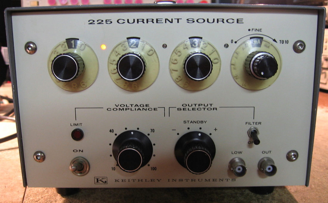
Keithley 225: DC current source in seven ranges from 100 nA to 100 mA full-scale. Voltage compliance to 100 volts. Basic accuracy spec is 0.5%. Can also modulate output with external low frequency AC. The three numerical digits plus the vernier pot allow resolution to about 0.02% of the range. Between this piece and the Keithley 261 (see below), I've got most of my current needs satisfied. Like most Keithley pieces built in the 1970s, basically bulletproof. (PDF) Grade: A
Advertised as "the unit doesn't power up," the obvious culprit was the frayed power cord. But I don't just mean frayed - I mean you could leave a power cord out on the street for 100 years and it wouldn't look as bad as this one. The previous owner at least had the good sense to pull the fuseholder cap off to dissuade anyone from attempting to use the piece. Although, even plugging the cord into an AC outlet wouldn't have been a good idea. I didn't have the matching fuseholder cap, so I had to replace the entire fuseholder as well as the power cord. The only other suspicious components were two 150V electrolytics whose body looked like it was made with yellow cardboard. Moreover, the top of cardboard cylinder could be pushed in 1/2". Both caps tested fine, but I pulled one out only to find that it was simply a standard Sprague silver-can electrolytic that was wrapped in yellow cardboard (I've usually seen them wrapped in clear vinyl). Calibration of the unit is fairly simple since once you set the reference voltage, everything else is done by fixed high-precision resistors. Everything was spot-on and didn't require any adjustment.
Advertised as "the unit doesn't power up," the obvious culprit was the frayed power cord. But I don't just mean frayed - I mean you could leave a power cord out on the street for 100 years and it wouldn't look as bad as this one. The previous owner at least had the good sense to pull the fuseholder cap off to dissuade anyone from attempting to use the piece. Although, even plugging the cord into an AC outlet wouldn't have been a good idea. I didn't have the matching fuseholder cap, so I had to replace the entire fuseholder as well as the power cord. The only other suspicious components were two 150V electrolytics whose body looked like it was made with yellow cardboard. Moreover, the top of cardboard cylinder could be pushed in 1/2". Both caps tested fine, but I pulled one out only to find that it was simply a standard Sprague silver-can electrolytic that was wrapped in yellow cardboard (I've usually seen them wrapped in clear vinyl). Calibration of the unit is fairly simple since once you set the reference voltage, everything else is done by fixed high-precision resistors. Everything was spot-on and didn't require any adjustment.

Keithley 261: Current source going from 100 microamps down to 0.01 picoamp. Three digit resolution and positive and negative current selection. The output connector is an SO-239 normally found on HF/VHF radios, not test equipment, but I guess Keithley wanted a nice big Teflon insulator. The circuit is very simple - a Kelvin-Varley voltage divider controlled by the three upper knobs and a set of high value range resistors in series with the divider controlled by the lower knob. The highest range resistor is 1 teraohm! I'd like to look at the range resistors, but they are encapsulated in a steel box. The basic accuracy is 0.25 to 0.5% and was verified with my HP 4140B pico-ammeter. I don't know what it is with Keithley knobs, but the "clear" plastic part over the numerals turns somewhat opaque after a while. (PDF) Grade: A
Advertised as working, it basically was when I received it. However, all the wafer switches needed a shot of tuner cleaner in order to get the currents to stabilize.
Postscript: The 1e-11 range wasn't working quite right, so I took apart the range resistor assembly and cleaned the resistor with alcohol. Seems OK now. The 1e-12 range reads a bit high on my HP 4140B pA meter, but then again, who can really trust readings that low in a non-metrology grade setting like my basement.
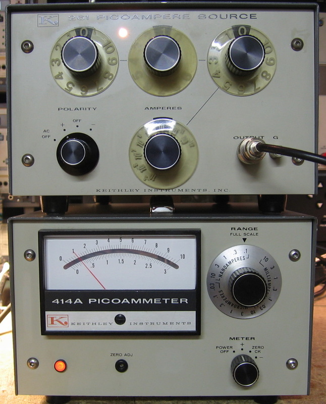
Keithley 414A: Solid-state picoammeter from 100 pA to 10 mA full-scale in seventeen ranges (1-3-10). Accuracy is +/-2% down to 10 nA range, and +/-4% below that. I already had the Keithley 261 pico-current source, so naturally I had to have the matching meter. The photo shows both units with a 10 pA source being correctly measured on the 414A. Unlike a lot of other analog meters whose accuracy seems to drop off markedly below about 1/4-full-scale, the 414A seems abundantly accurate all the way down to zero. Even though my HP 4140B pA meter is more capable, more accurate (and more expensive), it uses pesky triaxial connectors and my collection of triax cables isn't very good. Thus, I cannot get the 4140B down as far as I can with the Keithley. Of course, my Keithley 602 Electrometer (shown below) has everybody beat - providing you can figure out how to properly use it! (PDF) Grade: A
Advertised as working, it basically was when I received it. However, all the wafer switches needed a shot of alcohol in order to get the currents to stabilize. I was a bit scared to use more aggressive tuner cleaner. Even so, the meter went full scale on all ranges below about 10 nA for about an hour until the alcohol dried.
Advertised as working, it basically was when I received it. However, all the wafer switches needed a shot of alcohol in order to get the currents to stabilize. I was a bit scared to use more aggressive tuner cleaner. Even so, the meter went full scale on all ranges below about 10 nA for about an hour until the alcohol dried.
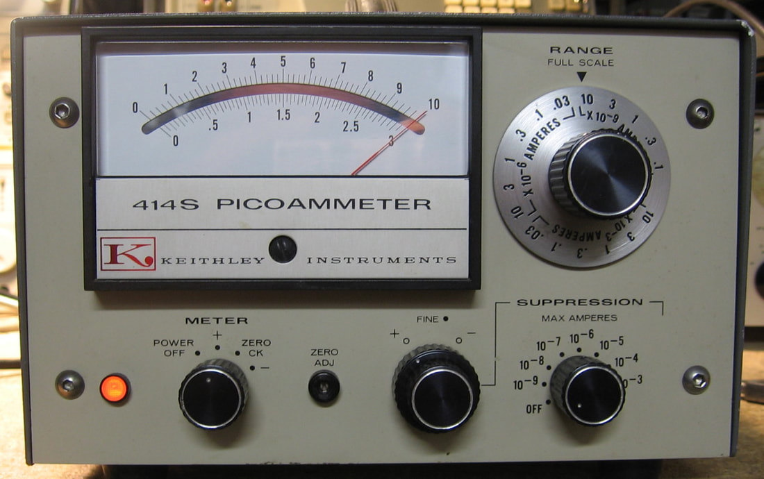
Keithley 414S: Solid state analog picoammeter. This came in a buy of 5 Keithley picoammeters, but the seller's picture only showed four. It wasn't until I opened the box that I saw I received one of these. I already had the 414A model, but I instantly noticed the two extra controls on the front panel. The "S" in 414S stands for suppression - a really cute feature. Suppose you are measuring 1.000 uA and want to see if the current jumped to, say, 1.001 uA. You aren't going to see this 1 part in 1000 change on an analog meter set on the 1 uA scale, and if you switch to the 1 nA scale, the meter will peg. So you use the suppression controls essentially to notch out your 1.000 uA so you can indeed use the 1 nA range. Architecturally, the 414S starts out the same as the 414A - namely a range switch with a pile of very accurate, high value resistors. But the 414S has a second range switch with a second set of very accurate, high value resistors to provide the exact current (in the opposite direction) for the suppression feature. It's almost like getting two picoammeters in one! (PDF) Grade: A
Nothing to do except put a fuse in the empty fuse holder and run through the adjustment procedure.
Nothing to do except put a fuse in the empty fuse holder and run through the adjustment procedure.
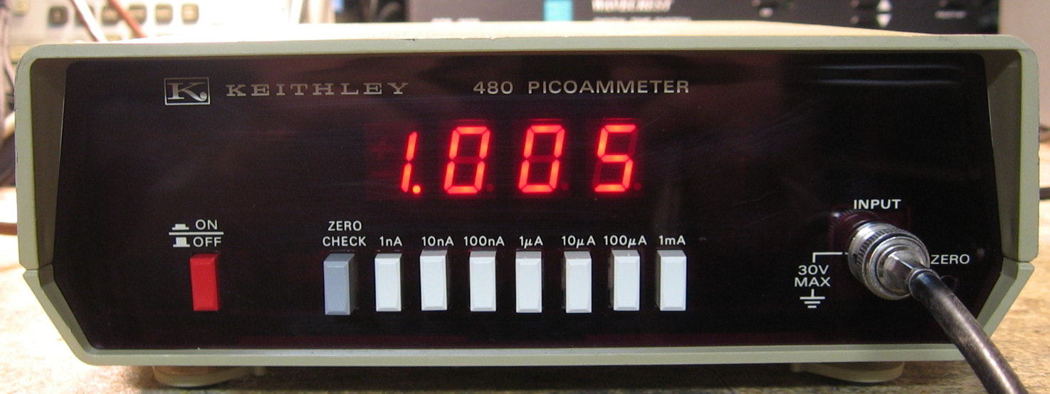
Keithley 480: 3-1/2 digit picoammeter. I guess Keithley decided to continue their very nice picoammeters into the digital realm. And they cranked the accuracy down to 0.5% (high ranges) and 0.8% (low ranges), rather than the typical 2% of the analog meters. Not much to say - press the button, read the numbers. (PDF) Grade: A-
Two of these came in a buy of 5 picoammeters. Both had notes describing the malfunction written in indelible red magic marker on the case (thanks a bunch for that). One of the units sprang to life after I cleaned the switches, but the other had a pretty bad offset. When I looked inside, there was evidence of a previous repair attempt. But it looked like the repairman decided the switches were the culprit, and rather than clean or replace them, he cut a bunch of traces and ran a bunch of jumper wires - almost as though there were unused switch sections he was borrowing for a bad one. Whether or not there are, I wasn't about to spend the time pouring over the schematics to find out. So I delegated this second piece as a parts mule (which came in handy for the Keithley 485 described below).
Postscript: Even though I took a couple of JFETs out of the second 480 parts mule, they were only there for overload protection. So I revisited the piece and found that the analog section was fine. It was a defective Intersil IC71C03 digital voltmeter chip that was sourcing voltage back out the input. I took an old Simpson 145 digital panel meter, removed the front panel of the 480, and wired in the Simpson. Works fine. Until I need a part out of the 480...

Keithley 485: 4-1/2 digit digital picoammeter. This is one of Keithley's better attempts at a picoammeter having accuracy specs of 0.1% (high ranges) to 0.4% (low ranges). This comfortably beats my HP 4140B which used to be the best picoammeter I had. Unlike the Keithley 480, this one autoranges. It also can show relative and log values. As mentioned in some of the previous picoammeter descriptions, I bought a Keithley 172, 414S, 480 (two) and 485 all for $50. One of my better buys since the 485 alone usually goes for $150-$200. But if you are shopping for a low current measurement device, the 485 is the one to get. (PDF) Grade: A
When received, this piece worked fine, but only on the 2 uA range. Every other range showed overload. The fact that one range worked fine proved that the A/D and that followed were fine and that the problem was in the range switching. Turns out that two FETs in the switching circuit were toast. Took me a while to find the second one since double failures are kind of rare. They were replaced with two FETs that I conveniently pulled out of the Keithley 480 parts mule.
When received, this piece worked fine, but only on the 2 uA range. Every other range showed overload. The fact that one range worked fine proved that the A/D and that followed were fine and that the problem was in the range switching. Turns out that two FETs in the switching circuit were toast. Took me a while to find the second one since double failures are kind of rare. They were replaced with two FETs that I conveniently pulled out of the Keithley 480 parts mule.

Keithley 602: Solid-State Electrometer (as contrasted to the earlier vacuum tube versions). Keithley made a bunch of slightly different models in the sixties and seventies (perhaps even later). This one is a battery powered, solid state unit circa 1974. Basically this thing measures voltage, current, resistance and charge. But this is not your ordinary VOM; it is designed for measurement of extremely low (current) and high (resistance) values; e.g., 0.3A down to 10 femtoamps full scale and 1 meg to 10 teraohms full scale. Accuracy ranges from 1 to 5% depending upon scale and function. It does this with a 100 teraohm input impedance and 5 femtoamp offset current. Not for the faint of heart or the novice due to its many different modes, settings and input connections. From a practical basement lab standpoint, it is reasonable down to about 100 pA and up to about 10 Gohms. At that point, one needs careful guarded connections and a sealed measurement box. But in those limited ranges, it seems just as accurate as my HP 4140B pA meter and HP 4329A high resistance meter. The voltage measurement is almost an afterthought and goes from 0.001 to 10 volts full scale, not that you would ever use this to measure voltages. Mechanically, the 602 is huge and it is difficult to appreciate that from the photo (shown here measuring a 147 Mohm resistor). Suffice it to say that you could fit about six Simpson 260s in the same volume. Built like a tank, one can only admire the insides from afar. Because rumor has it that if you so much as touch one of the high value resistors inside, the thing is ruined. This thing is so sensitive that the manual stipulates you should leave it on for a couple of hours after it has been dormant in order for it to stabilize. The 602 input is a triax connector. Not that triax connectors bother me because I have cables and adapters for my HP 4140B triax input. But the 602 uses the older 2-prong style on the barrel, not the modern 3-prong stuff I have. Very conveniently, the seller included not one, but two of the proper connectors with cables. (PDF) Grade: A-
I knew I was in for some work before I received this unit since the batteries had to be dead. It requires six standard 9V batteries and one 1.35 volt mercury battery (for the ohms function only). The 9V batteries all were dead and easily replaced. The 1.35 volt mercury battery actually measured 1.35V, surprisingly. When I powered it up, the meter didn't move at all in any range or with any input. A closer look revealed the meter glass slightly loose and the needle bent and touching the glass. So I removed and dissected the meter, bent the needle back, glued the glass back down and reinstalled. Now the meter moved, but all the measurements were completely erroneous. I took off all the inside covers only to find the input board dangling in the breeze. Reinstalled the input board and all is well. The 1.35V battery, being a mercury, holds the voltage until the very end, which could be tomorrow or 10 years from now. So I really should replace it. Since mercury batteries are now illegal, fat chance. My first thought was to throw an LM317 adjustable regulator off of a 9V battery. But the regulator would draw a few mA even when the 602 was off, so that's not too good. Keithley came out with a service note that allows the thing to be run off of a 1.5V battery by changing three resistors. But I really don't want to put my hands inside. The solution was found online with a clever circuit based on an LM10CN op-amp/voltage standard that should only draw about 1 uA when not being used (if I believe the author's claim). Parts are on order and the next postscript will describe the results.
Postscript: The circuit I came across using the LM10CN didn't quite make sense to me as it used a strange arrangement that relied upon a transistor to unhook the ground line to the op-amp. I breadboarded the circuit with a 741 op-amp just to see what would happen and it was drawing >1 ma with the load off. So I decided to go a simpler route and use an LP2951 adjustable micropower regulator. Just a couple of external resistors, an adjustment pot, a couple of electrolytics and I have exactly 1.35V coming from two AA batteries. I've measured the current draw when the Keithley 602 is powered off and it is 57 microamps (it is 157 microamps when the meter is on, regardless of setting). So I should get almost 4 years out of a good set of batteries.
Postscript^2: Yes, about 4 years later, I noticed the 602 wasn't reading resistance correctly. I had already replaced all of the 9V batteries, but I forgot about the two AA batteries providing my 1.35V source. And they had leaked pretty badly too. New AA batteries cured all ills.
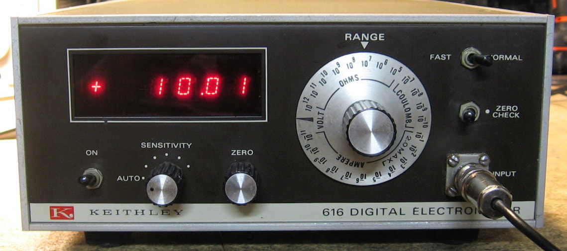
Keithley 616: Digital electrometer (shown here measuring a 100 Mohm 2% resistor). A more modern version of my Keithley 602 (see entry above), the 616 provides a 3-1/2 digit display of volts, ohms, amps and coulombs with a best-case accuracy of 0.2%. A little easier to use than the 602 analog version, it still requires a consultation with the manual especially in "fast" mode. Fortunately it uses the same 2-prong triax cable/connector as the 602. I would give it the same A- grade as the 602, but I'm knocking it down a notch because it managed to give me a 275 volt shock as I was hooking up the alligator clips to a resistor (my own fault). (PDF) Grade: B+
The seller described a broken fuse holder and that was indeed the only thing wrong with it. A simple fix.
Postscript: The second digit's decimal point stopped working and a closer examination revealed it was the actual LED, not the driving circuitry. I didn't have any of the real old HP LEDs, so I used the more modern one for the exchange. Maybe some day I will replace them all so at least they match perfectly.
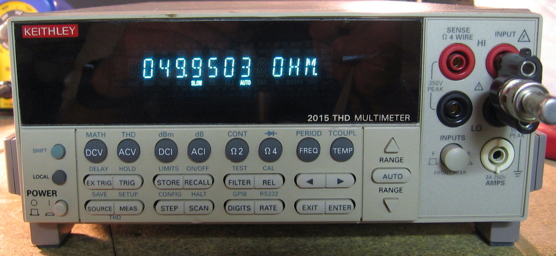
Keithley 2015THD: 6-1/2 digit multimeter with distortion measurement. The 2015THD shares the same basic platform as the ubiquitous Keithley 2000 DMM. But in the space where the 2000 could have the optional 10-channel scanner card, the 2015THD puts a distortion measurement and limited function generator board. Now the base 2000 model retails at $1140, and the 10-channel scanner card will set you back another $550. How the THD card bumps up the 2015THD price from $1140 to $4820 is totally beyond me, and I would argue, simply a total rip-off. The specs for the DMM portion are reasonable for a 6-1/2 digit DMM, but not particularly good in comparison, say, to an HP 3456A. While the DCV and ACV accuracies are about that of the HP 3456A, the resistance accuracy (90-day) is more than 2x worse. The THD functions go to 20 kHz with an accuracy of 1.5 dB and a residual noise floor of -65 dB(full-scale), meaning the 2015THD won't be replacing my HP 8903A audio analyzer any time soon. The function generator outputs sinewaves or a 45% duty-cycle pulse train with amplitude accuracy of about 0.3% and a frequency accuracy of 0.015%. Again, maybe nice to have in a single unit, but certainly not the fidelity of a dedicated generator. Likes: 1) does everything, DCV, ACV, DCI, ACI, 2W ohms, 4W ohms, Freq (period), Continuity, Diode and Temperature (with thermocouple); 2) small size; 3) update rate and filter selection. Dislikes: 1) the display is somewhat hard to read - the small horizontal segments that turn a zero into an eight are easily missed by my aging eyes; 2) cannot set the integration time to greater than 10 PLC (although can block average those through the filter); 3) very cheap and flimsy case, 4) calibration ranges cannot be skipped (if, for instance, you don't have a 2 amp sinewave generator!). Should grade it at B+ because of the ridiculous MSRP, but I'll give it an A- because I got mine for $125. (PDF) Grade: A-
The seller was offering a bunch of these and the photo of the one used in the eBay listing showered the word "bad" written on the cover. But I took a chance not knowing what I was going to get. The 2000 series has a history of leaking electrolytics which destroy the board (the caps are too close to the hot voltage regulators), but I was pleasantly surprised to find that the 2015THD has a later board revision and my caps were adequately spaced from the regulators and the board was pristine. Other than a front/rear panel switch which needed a spritz of cleaner, the unit worked fine. The ($60) VFD display is about half the normal brightness and will be replaced when Keithley manages to get more in stock. In the meantime, I spent $35 for a new handle/feet set since my unit was absent those.
Postscript: Keithley lied when they quoted $60 for a new VFD. They will only sell the complete front panel for $250. Bah, humbug. I'm trying to negotiate with Newhaven Display for one, but since they make them as a custom order for Keithley, my chances don't look good. In the meantime, I boosted the filament current a bit by paralleling 22 ohms across each of the four 12.1 ohm current limiting resistors on the display board.
Postscript^2: Newhaven Displays came through and supplied a new VFD. The picture now shows the unit with the new display.
Postscript^3: The front/rear switch was somewhat immune to my efforts to clean it, so I put in a new one.
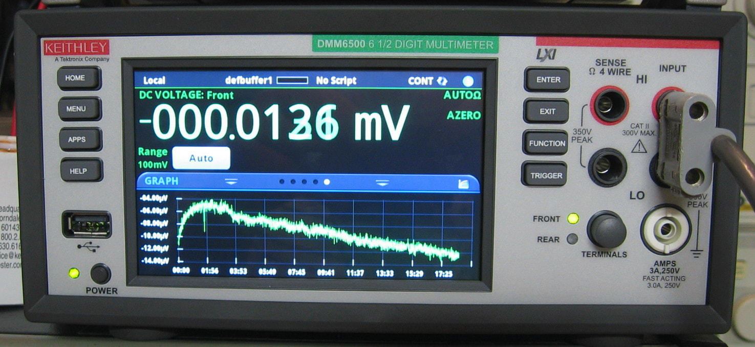
Keithley DMM6500: 6-1/2 digit DMM. Treated myself to a modern DMM because I really wanted the graphing, statistics and data export that are now standard in today's instruments. I won't bore you with the specs, but this is a 25 ppm class machine (DCV @ 1 year). I would have loved to get the DMM7510 7-1/2 digit version, but it is nearly four times the cost. The DMM6500 lists for $1,140, but I got mine with a 10% discount from a major USA dealer. That puts it at about $1K, which makes it a much better deal than the $1,400 HP/Agilent/Keysight 34665A. Somewhat strange is that Keithley optimized the unit to work best at between 1 and 5 power line cycles per measurement. That tends to make the displayed numbers change really fast (hence the blur in the photo). I'm used to cranking the #PLC to >50. The only negative thing I can (and therefore must) say is that the documentation is a bit lacking. A lot of the functionality is not explained in the User Manual - you must consult the Reference Manual. And even that document doesn't really explain very much. (PDF) Grade: A-
The unit threw a "date not set" warning about 20 months after I bought it. This is a symptom of a low CR2032 battery that is used solely to keep alive the real time clock chip. I'm not sure if the RTC is powered off the line if the unit is plugged in and in standby. I usually throw the main kill switch to my lab every evening, so the battery should get plenty of use. But 20 months? Really, Keithley. Around the time my battery went, there were a slew of postings on eevBlog with others reporting the same problem. Obviously, a new CR2032 fixed all, despite Keithley's ridiculous warning in the manual that the battery is only replaceable by them. And the old battery voltage was 1.38 V in case you want to know.
Postscript: The battery drain problem was fixed in firmware release 1.7.3.

Kikusui: DPS-V-10-0.05: These are semi-worthless DC "calibrators" that will do 50 ma up to 10 volts. Kikusui has the service manual on-line, but the link says to "contact factory." I did and never heard back from them. (--) Grade: D+
Repaired one (relay), but did not bother to repair the other one since they are basically useless.
Repaired one (relay), but did not bother to repair the other one since they are basically useless.
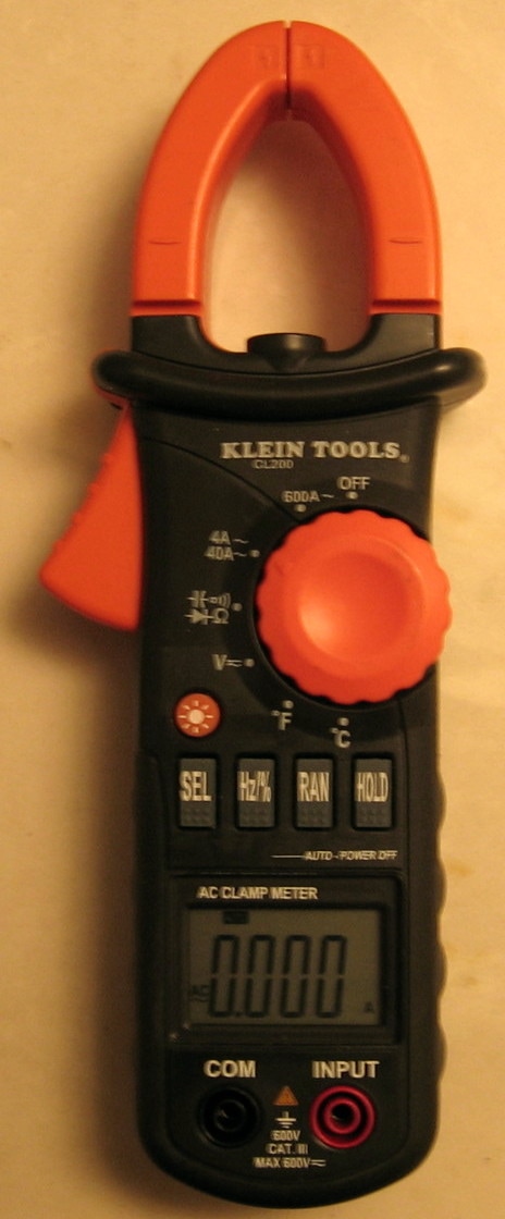
Klein CL200: AC clamp meter plus DMM. I always wanted a clamp meter, so I took the opportunity to purchase a cheap Chinese version for a mere $25 shipped (the retail price for a new CL200 was about $50). Only thing was that the seller gave me TWELVE of these units for $25. And much to my surprise, they all had three AAA batteries, most of which were fairly new. OK, all twelve were advertised as broken, but I figured I could get a couple of them working. And so I did - I managed to get 9 of them working fine until I gave up from boredom. The CL200 clamp is rated to 600A and the DMM will do DCV, ACV, ohms, capacitance, continuity, diode, frequency, duty cycle and temperature (with a type-K thermocouple). The banana jack inputs are rated CAT III (600V), but you would have to be absolutely insane to hook up 600V to this puppy once you have had a look inside. Since you cannot do a direct current measurement, there is no need for a fuse or any other kind of input protection. And the banana plug to board connections are laughable. The board is almost exclusively surface mount, with one chip "blob" doing all the computations. But there are a couple of regular through-hole transistors in there for good measure. The accuracy spec is in the one percent-ish range but there are a bunch of pots inside that probably could be turned to calibrate the unit if only I had a schematic. I got what I wanted, namely a clamp meter. (--) Grade: B-
As mentioned, all twelve of these were dysfunctional upon receipt. I immediately destroyed one of them trying to figure out the right way to disassemble things. I used the parts from three of the worst offenders to fix the remaining eight units. It was mostly broken wires, dirty rotary switch contacts and bad piezo-buzzers. One of them had a malfunctioning ohms circuit and by chance I stumbled across a shorted transistor which I then pulled out of a parts unit.
As mentioned, all twelve of these were dysfunctional upon receipt. I immediately destroyed one of them trying to figure out the right way to disassemble things. I used the parts from three of the worst offenders to fix the remaining eight units. It was mostly broken wires, dirty rotary switch contacts and bad piezo-buzzers. One of them had a malfunctioning ohms circuit and by chance I stumbled across a shorted transistor which I then pulled out of a parts unit.

Krohn-Hite 3202: Dual LPF/HPF to about 2 MHz. Several 4-pole filters inside. Pretty straightforward and doesn't need much more elaboration. (---) Grade: B-
This had a multitude of cold solder joints - almost everywhere a wire went into a board. They were pretty easy to find. Also needed new BNC jacks and for some reason a lot of the heatsinks were very loose.
Postscipt: After a couple of years of sitting on the pile unused, I tried the 3203 only to discover that the right channel was working improperly. It just needed some more resoldering of a couple of cold joints. The Krohn-Hite boards have 1/8-inch holes that are filled with solder; connecting wires are simply jammed somewhere in the hole. This time, I removed the board, completely desoldered the "cups," and reattached the wires with new solder.
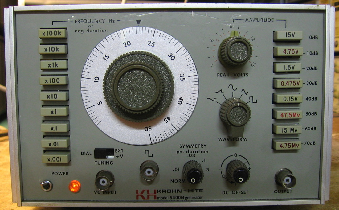
Krohn-Hite 5400B: 5 MHz function generator. The K-H 5400B is a standard issue analog function generator with absolutely no distinguishing characteristics. The front panel nomenclature pretty much reveals its capabilities: 0.002 Hz to 5 MHz, full scale voltages of 4.75 mV to 15 V peak-to-peak (into 50 ohms) and sine, triangle, square and positive and negative ramp waveforms. Basic amplitude, DC offset and symmetry controls with <0.5% sinewave distortion. The frequency can also be controlled via an external input DC voltage. This is the third Krohn-Hite piece I've bought and I must admit that I am totally unimpressed. Simply boooooring. (OM) Grade: B-
The seller advertised this as "output incorrect and switches noisy." OK, if you count the output being zero as incorrect, then the seller was right. Hooking the output to the scope revealed no waveforms coming out regardless of front panel settings. A quick check of the +22V and -22V power rails showed them both to be at 0V. An ohmmeter revealed the two rails had 0.5 ohm resistances to ground. There are about 20 assorted tantalum capacitors hooked up to these two rails and I pulled them all out until I found the two shorted ones. Of course, they were the last two left on the board that I pulled. With the power supplies now restored, I was getting output but the pushbutton switches and pots were very noisy and marginal at best. So I drilled holes through the cases of the 17 switches and 3 pots and squirted in tuner cleaner. With those now restored, I noticed that as I turned the main tuning dial, the frequency would increase and then abruptly go very low and start climbing up again. I pulled out the main tuning pot and discovered that it was a continuous turn pot. I don't know if that was by design or the stops inside snapped off. Anyway, the pot was incorrectly coupled (by the last repairman) to the dial in such a way that it was tuning through the boundary point. So I slipped the coupling hex screws and set it correctly. I also noticed when I was first looking at the power supply problem that the thermal pads under the two pass transistors were ripped, so I replaced them as a precautionary measure. Finally, I went through their alignment process which was almost as poorly written as Tektronix pieces.
The seller advertised this as "output incorrect and switches noisy." OK, if you count the output being zero as incorrect, then the seller was right. Hooking the output to the scope revealed no waveforms coming out regardless of front panel settings. A quick check of the +22V and -22V power rails showed them both to be at 0V. An ohmmeter revealed the two rails had 0.5 ohm resistances to ground. There are about 20 assorted tantalum capacitors hooked up to these two rails and I pulled them all out until I found the two shorted ones. Of course, they were the last two left on the board that I pulled. With the power supplies now restored, I was getting output but the pushbutton switches and pots were very noisy and marginal at best. So I drilled holes through the cases of the 17 switches and 3 pots and squirted in tuner cleaner. With those now restored, I noticed that as I turned the main tuning dial, the frequency would increase and then abruptly go very low and start climbing up again. I pulled out the main tuning pot and discovered that it was a continuous turn pot. I don't know if that was by design or the stops inside snapped off. Anyway, the pot was incorrectly coupled (by the last repairman) to the dial in such a way that it was tuning through the boundary point. So I slipped the coupling hex screws and set it correctly. I also noticed when I was first looking at the power supply problem that the thermal pads under the two pass transistors were ripped, so I replaced them as a precautionary measure. Finally, I went through their alignment process which was almost as poorly written as Tektronix pieces.
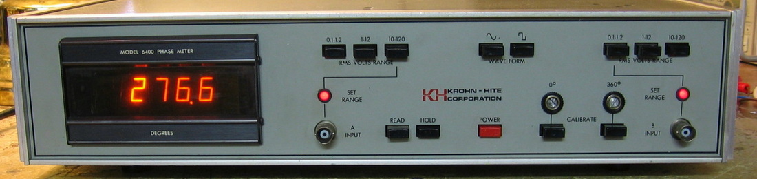
Krohn-Hite 6400: 10 Hz - 5 MHz digital phase meter. A weaker version of the HP 3575A, but does what you would expect. Hook up two narrowband signals and the phase difference appears on the digital display. Krohn-Hite broke the mold on this one when it came to "specmanship." The brochure would have you believe that the basic accuracy is 0.1 degrees. That may be true at low frequencies, but a closer examination of the specs show that the accuracy degrades by 0.7 degrees per 100 kHz, making this thing only accurate to 35 degrees at 5 MHz. You would be more likely to measure the correct phase difference by holding the two BNC cables to both temples on your head and guessing the answer. The digital display is a Newport 400A/S-3 which uses 150V plasma tubes. These are probably on their way out, so if I can buy cheaply a more modern 400A/S-3 that uses LEDs, I might replace it. The build quality on this unit is on par with some of the off-brands like Leader or BK Precision. At least it came with the service manual. (OM) Grade: B-
Advertised as the seller as non-responsive to any input. A quick check of the power supply showed excessive 120 Hz ripple on all rails. I pulled the two main filter caps and both measured >50 ohms ESR. Another cap on the main board had leaked white powder and because all the caps were the silver-colored Spragues (the absolute worst of all time), I replaced all of them in the unit. Confirmed the operation, did the alignment and tightened all the loose hardware.
Postscript: Not that this is a further repair note, but I was perusing the service manual and came across Krohn-Hite's one-year "warranty" statement. And I quote, "This warranty does not apply to electron tubes, fuses, batteries, transistors and other semiconductor devices." Really? I can see maybe the tubes, fuses and batteries, but no warranty on semiconductors? OK, I'll cut them some slack because in 1974 when this unit was built, quality semiconductors had only been available to every damn test equipment manufacturer for what, at least 10 years? So I went on Krohn-Hite's web page and downloaded a random manual from 2002. Guess what, same semiconductor exclusion. These guys have to be kidding.
L : Leader
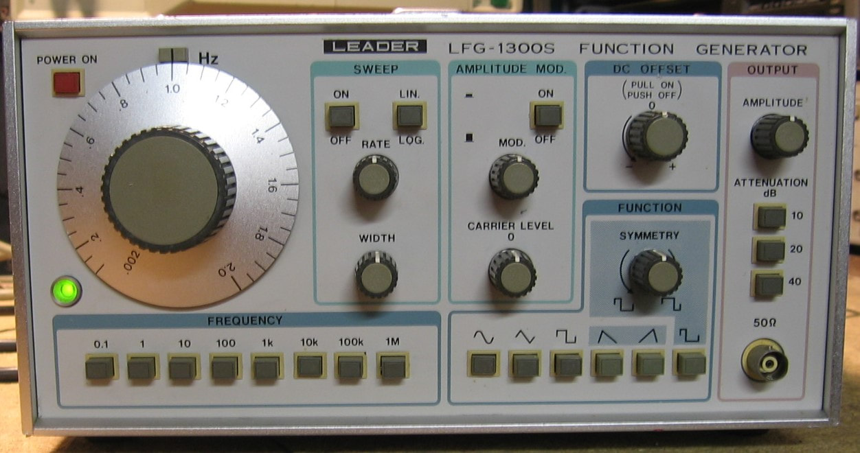
Leader LFG-1300S: Analog function generator to 2 MHz. In addition to the normal sine, square and triangle waveforms, the 1300S will do AM modulation and frequency sweeps. Beyond that, it is pretty much what you would expect from a mid 1980's consumer grade function generator. (PDF) Grade: B+
Advertised as making a "BZZZZ on the output," the seller's description was a bit baffling. Anyway, upon power-up, the thing had no output regardless of setting. A quick check of the 5, -5, 15, -15, 10 and -10 volt supplies showed the 5V was about 4.2V. Switching the voltmeter from DC to AC revealed a huge ripple, so the faulty electrolytic capacitor on the 5V supply was replaced. The 1300S the seemed to function OK, but needed a lot of cleaner squirted into the switches. And while I was going through the various frequency ranges, I noticed what looked like oscillation when the unit was set at 200 kHz to 600 kHz. After a day of fruitless debugging, it dawned on me to look at the 10V rail, since that was what is used in the basic triangle generator integrator circuit. And indeed, there was the oscillation. The 10V (and -10V) supplies take 15V inputs and use pass transistors with op-amps in feedback. The 47 uF output capacitor on the 10V rail had dropped down to about 1 nF and the 10V supply started to oscillate. Once the capacitor was replaced, all was well. See the Repair section at the bottom of this web page where it says to always look at the power supplies with a scope just to make sure there isn't some high frequency stuff going on that your DCV and ACV meter can't see. A very wise recommendation in this case!
Advertised as making a "BZZZZ on the output," the seller's description was a bit baffling. Anyway, upon power-up, the thing had no output regardless of setting. A quick check of the 5, -5, 15, -15, 10 and -10 volt supplies showed the 5V was about 4.2V. Switching the voltmeter from DC to AC revealed a huge ripple, so the faulty electrolytic capacitor on the 5V supply was replaced. The 1300S the seemed to function OK, but needed a lot of cleaner squirted into the switches. And while I was going through the various frequency ranges, I noticed what looked like oscillation when the unit was set at 200 kHz to 600 kHz. After a day of fruitless debugging, it dawned on me to look at the 10V rail, since that was what is used in the basic triangle generator integrator circuit. And indeed, there was the oscillation. The 10V (and -10V) supplies take 15V inputs and use pass transistors with op-amps in feedback. The 47 uF output capacitor on the 10V rail had dropped down to about 1 nF and the 10V supply started to oscillate. Once the capacitor was replaced, all was well. See the Repair section at the bottom of this web page where it says to always look at the power supplies with a scope just to make sure there isn't some high frequency stuff going on that your DCV and ACV meter can't see. A very wise recommendation in this case!
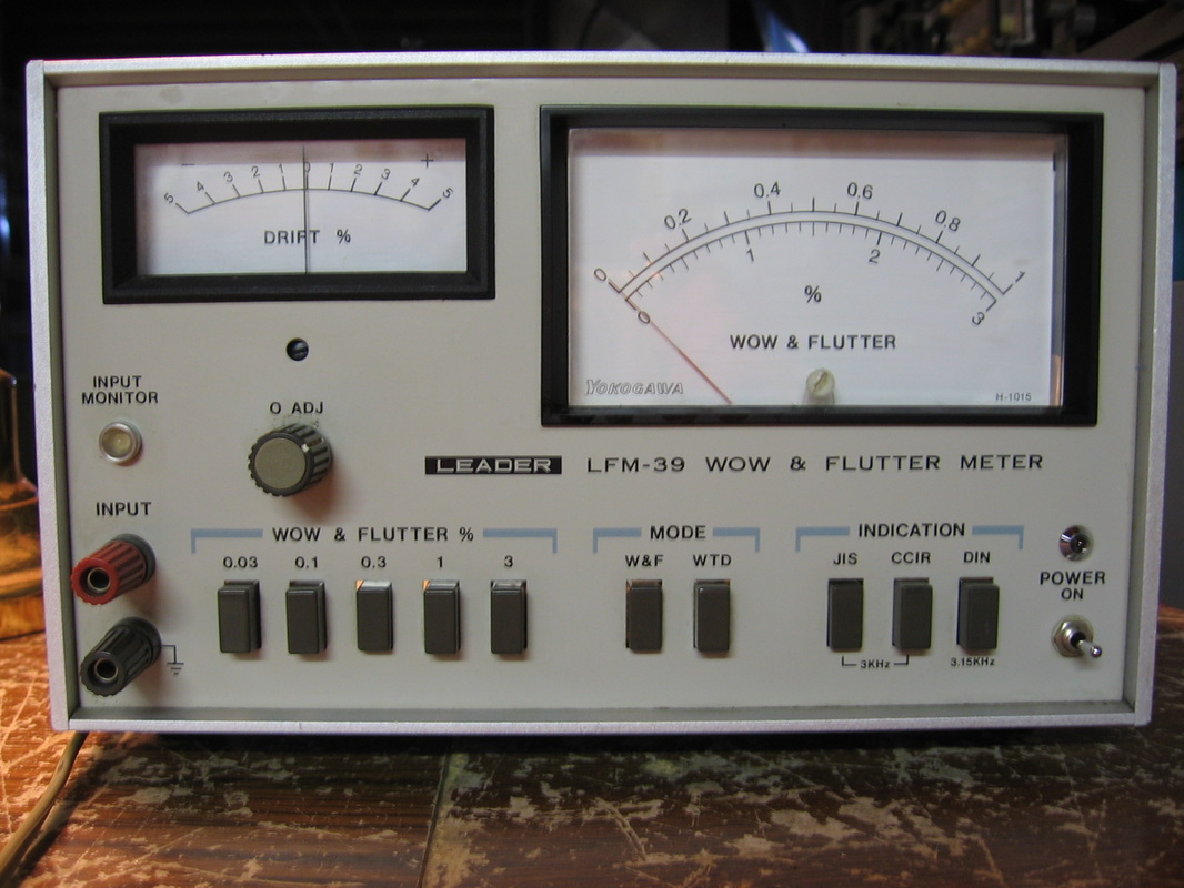
Leader LFM-39: Wow and Flutter meter. I bought this to test the Racal 14DS and HP 3964A instrumentation recorders. It works very nicely and proved that the capstan re-rubbererizing was done very well on the recorders.
(---) Grade: B+
(---) Grade: B+
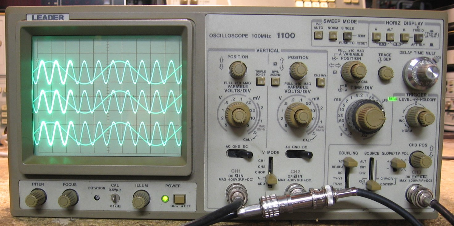
Leader 1100: 100 MHz analog oscilloscope. This is a Japanese oscilloscope from the 1990 time frame which is similar to several of my other generic Korean-built analog scopes of that era. Although it is rated to 100 MHz, the time-base knob only goes down to 50 nsec/div, so you have to engage the x10 multiplier to see a 100 MHz signal. The V/div goes down to 5 mv/div, but there is also a x10 multiplier down to 500 nsec/div (for signals less than 5 MHz). Although it is a dual-channel scope, there is a third channel that can be used not only as an external trigger, but can also be displayed on the CRT. This channel only has two fixed V/div ranges, similar to my Tektronix 2246 scope, so it is not truly a fully functional third channel. The 1100 is also has dual-time bases and you get the normal delayed intensity sweeps. The controls are well thought out and there isn't much capability missing. The Toshiba CRT is one of the better ones in terms of brightness and clarity that I've seen at this price point. The build quality is typical of consumer-grade electronics, but the 1100 has a mix of through-hole and SMT parts (a few little SMT daughterboards scattered about). (Operation PDF only) Grade: B+
Advertised as getting a trace on channel 1, I bought this for $49 (I no longer buy oscilloscopes unless I see something on the CRT in the sales listing). When received, I saw a flat trace on channel 1. The problem was that the trace was flat regardless of the input signal. And channel 2 showed no trace at all. Channel 3, however, seemed to work just fine and allowed me to verify the timebases were working correctly. So obviously something was wrong with the channel 1 and 2 input sections. When I took the covers off the 1100, I saw that the two BNC input jacks went through 10 ohm resistors with the far end of the resistor waving in the breeze! Moreover, a couple of ground wires were unattached. I managed to figure out where the two resistors and ground wires hooked up to the switch board and fired the scope back up. Channel 1 then performed flawlessly, but still nothing on channel 2 unless I cranked the V/div way down - and then the trace was partially off the screen. While I was figuring out how to get the attenuator/preamp board out, the channel 1 trace suddenly went haywire, then a bright green fuzzy dot appeared on the CRT, and then the CRT went dark. Checking the 5, 12 and -12 V test points on the main board showed that the 12 V had dropped to 2 V. I removed the P/S board and the fault followed, proving the problem was isolated to the P/S. A little debug revealed a faulty LM7812 regulator which was suitably replaced. With the scope at least now operating (incorrectly) as before, I removed the attenuator/preamp board (and it was now obvious that the previous owner tried this and forgot to hook things back up to the board). With the board on the bench, I used a signal generator to verify that the attenuators were working correctly on channel 2. But one look at the preamp section, with about 100 SMT parts and no schematic, convinced me that repair was futile. But as long as the board was sitting on the bench, I did a bunch of comparative resistance measurements on the two channels (identical parts and layout). I found one spot, almost by accident, where it read 47 ohms on channel 1 and 5 megohms on channel 2. Turns out one of the SMT resistors must have had a cracked joint since a quick reflow with the soldering iron put it back to 47 ohms. I reinstalled the board and voila - works like a champ. I got REALLY lucky on this one!
Advertised as getting a trace on channel 1, I bought this for $49 (I no longer buy oscilloscopes unless I see something on the CRT in the sales listing). When received, I saw a flat trace on channel 1. The problem was that the trace was flat regardless of the input signal. And channel 2 showed no trace at all. Channel 3, however, seemed to work just fine and allowed me to verify the timebases were working correctly. So obviously something was wrong with the channel 1 and 2 input sections. When I took the covers off the 1100, I saw that the two BNC input jacks went through 10 ohm resistors with the far end of the resistor waving in the breeze! Moreover, a couple of ground wires were unattached. I managed to figure out where the two resistors and ground wires hooked up to the switch board and fired the scope back up. Channel 1 then performed flawlessly, but still nothing on channel 2 unless I cranked the V/div way down - and then the trace was partially off the screen. While I was figuring out how to get the attenuator/preamp board out, the channel 1 trace suddenly went haywire, then a bright green fuzzy dot appeared on the CRT, and then the CRT went dark. Checking the 5, 12 and -12 V test points on the main board showed that the 12 V had dropped to 2 V. I removed the P/S board and the fault followed, proving the problem was isolated to the P/S. A little debug revealed a faulty LM7812 regulator which was suitably replaced. With the scope at least now operating (incorrectly) as before, I removed the attenuator/preamp board (and it was now obvious that the previous owner tried this and forgot to hook things back up to the board). With the board on the bench, I used a signal generator to verify that the attenuators were working correctly on channel 2. But one look at the preamp section, with about 100 SMT parts and no schematic, convinced me that repair was futile. But as long as the board was sitting on the bench, I did a bunch of comparative resistance measurements on the two channels (identical parts and layout). I found one spot, almost by accident, where it read 47 ohms on channel 1 and 5 megohms on channel 2. Turns out one of the SMT resistors must have had a cracked joint since a quick reflow with the soldering iron put it back to 47 ohms. I reinstalled the board and voila - works like a champ. I got REALLY lucky on this one!
M : Marconi, Mercury
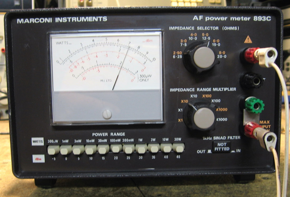
Marconi 893C: Audio frequency power meter, 20 Hz to 35 kHz. This totally passive meter (no AC power required) is useful not only for measuring audio amplifier power output, but also for determining source impedance. There are 10 power ranges and 48 internal impedance loads. To determine source impedance, simply dial in the impedance that gives the maximum power reading on the meter. The circuit is basically one large multi-tap transformer followed by a selection of over 140 resistors (0.25% tolerance). Some diodes and caps round out the meter circuitry. While Marconi is long gone, an almost identical unit is still being sold by IET Labs (GenRad 1840A) for $4,145. The Marconi 893C that I purchased, in absolutely mint condition inside and out, was a bit cheaper - $20. (PDF) Grade: A-
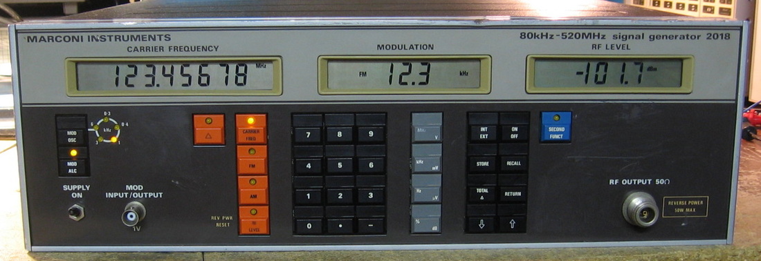
Marconi 2018: 520 MHz synthesized RF signal generator. This is basically a clone of HP 8656/7 series with pretty much the same features and specifications. They made a 2019 version that doubles the frequency to 1024 MHz. Later on, they made a 2018A and 2019A that adds a few more mostly useless buttons on the front panel. The general claim on these units is that their phase noise is superior to the HP versions. But my spectrum analyzer says that ain't so at offsets < 1 kHz. Very nicely made, similar to Wandel & Goltermann's construction with all boards in separate modules and easily accessible without extender cards. Oh, then there is that pesky attenuator (see the repair comments). Marconi had the good sense to include (as standard) an ovenized oscillator. The piece uses an EAROM instead of a battery backup meaning you have to physically store the configuration if you want it to start that way the next time it is powered up. The internal audio oscillator for the AM/FM modulation, which can be selected from 5 internal frequencies, is superb: -75 dBm distortion at 1 kHz. Unlike my HP 8657A, the 2018 only draws 54 watts and has no fan. (PDF) Grade: A-
Advertised as "LCDs dark, button LEDs lit, and has a burnt capacitor smell." Other than blown up tantalums, I didn't know that capacitors had a smell. But that description was mostly correct upon receipt, although I didn't smell anything because I was afraid to power it up. I removed the covers and looked for burned parts - none to be found. I then ohm-ed out the electrolytics on the P/S board and found the main cap on the -15V line shorted. I replaced the cap and flicked the power switch. The front panel LCDs lit with the error code "L" which means a checksum error in the EAROM (which also stores cal constants). But the manual says that the unit will still work fairly well even with that error. My problem was that there was absolutely no RF output. The problem was quickly isolated to the mechanical 120 dB step attenuator. The attenuator consists of five sections, 10, 20, 30, 30, 30 dB, each with two microswitches to place the section in or out. This is all in a sealed metal box with ten little plastic posts coming out from the ten switches. Sitting above each pair of switches is a solenoid with some metal ears that press down on the posts. I could see that some of the solenoids were not plunging the posts down far enough and some were not releasing the posts enough when non-energized. The solenoids have adjustment screws and by also bending the ears, I was ultimately able to align everything. Except that the attenuator still did not work correctly. The manual warns the user not to try to dissect the attenuator, but I took that as an insult and reached for the screwdriver. 2-1/2 hours later I had successfully disassembled the attenuator, soaked all the switches in alcohol and reassembled it. Everything works fine, but I bet the attenuator ends up being a maintenance headache. My other gripe is that I can see lots of adjustments on the various boards. Other than seeing them on the schematics, the service manual says nothing about them. The calibration is done via software and retained in the EAROM. So perhaps it would be possible to tweak the oscillator's phase noise a little. I'll never know As far as the EAROM error, the EAROM was actually fine given that I could see all of the cal constants the previous owner had stored. I could also see a -2 dB stored level adjustment which explained why the spectrum analyzer was 2 dB low. I removed the offset and followed the procedure to compute and store a new checksum. Problem solved.
Postscript: Well, my comment that the attenuators would ultimately be a maintenance headache was prophetic. Despite several cleanings and adjustments, the thing simply wouldn't output the correct levels. I'm afraid - go ahead, sing along - "it's dead, Jim." The attenuator is really a stupid design because it uses switches inside the sealed unit and external solenoids to mechanically actuate the switches. Why not simply put relays inside like everybody else? [Note: I'm being a little harsh here, because I more recently got an HP 3335A which uses a similar attenuator design and that one was and is about the most accurate attenuator I've ever seen]. Now there are a lot of step attenuators on eBay (I'm obviously not going to pay retail from a real vendor) and I was extremely fortunate to find (for $35) EXACTLY what I needed, a 120 dB attenuator with 10, 20, 30, 30, and 30 dB sections. Of course, it required 12 VDC and TTL-level control inputs, but that was easy to supply by modifying the Marconi's control board with some pull-up resistors and throwing in a 7812 regulator off of the existing 20 VDC. The cabling had to be altered a bit as the old attenuator used an SMC plug on the input and the new one used an SMA jack. The output cable had the proper SMA connector, but the whole connector came off in my hand as I was positioning it. Thus, a new SMA to bulkhead N assembly was used. All in all, works very well. Not quite as good as the attenuator in my HP 8657A which shows about a 0.2 dB variation on the spectrum analyzer as I step from 0 to -60 dBm in 10 dB increments. The one in the Marconi has more like a 0.5 dB variation. Makes sense as the manufacturer spec (JFW) is about 1 dB for similar models (the one I bought on eBay was originally a special order from JFW which makes it even more remarkable that I found it)
Postscript^2: Originally, I simply bypassed the original attenuator assembly and used the replacement attenuator. Upon further reflection, it occurred to me that the original attenuator had a reverse power protection relay and associated circuitry inside which was probably worth keeping. So I opened up the attenuator and simply ran a wire from the input jack to the protection relay, bypassing the five attenuator sections (I learned the hard way that it wasn't quite that simple, because the attenuator sections were still in-line in parallel with the wire; I therefore had to physically cut the traces to the first and last section). Then I took the output of my replacement attenuator and ran it into the old attenuator. So I essentially have the old assembly with just the five attenuator sections replaced by the new one. Voila.
Postscript^3: One of the digits on the LCD frequency display was acting up (stuck segments), so the digit's CD4056 driver chip was replaced.
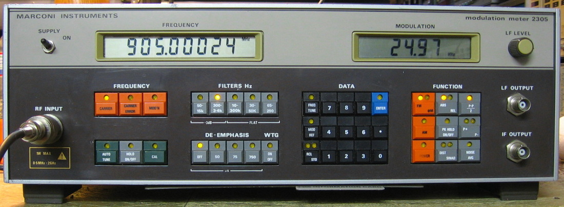
Marconi 2305: Modulation meter good to 2 GHz. Pretty much a copy of the HP 8901A/B meters including a substantial set of secondary menu items. Calibration all done via firmware - I only found one pot to adjust (bah humbug). (PDF) Grade: A-
Advertised as doesn't power up, but it powered up just fine for me. There was an intermittent on the front-end attenuator board that was causing some loss of sensitivity. It seems OK now and I haven't been able to identify the cause. I guess I'll just have to wait until the fault becomes more permanent.
Postscript: Powered the 2305 up one day and it threw all kinds of errors and the readings, although mostly correct, were suffering from a lack of input sensitivity again. The digital errors were cured by reseating the boards. The sensitivity came back to normal as I was probing the attenuator board with a scope probe. Perhaps there is a marginal solder joint and I should touch the board up. Mabye next time...

Marconi TF-2013: 800 - 960 MHz FM signal generator. This is a very odd piece, both visually and functionally. It will generate up to 30 kHz FM deviation with up to a 3 kHz modulation frequency over the 800 to 960 MHz band. That's basically it. It has some very odd controls, however. The RF frequency is set from the large (vernier ganged) dial on the left. However, next to that is a fine-tune control and another labelled knob and switch that also alter the frequency. The output amplitude is set from the main dial in the middle and covers nominally 0 to -130 dBm. The modulation frequency and deviation are set from two calibrated dials and switches. At the right are two meters and knobs that calibrate the modulation and RF. Of course, I'm just guessing here as I can find no manuals or descriptions of the TF-2013 at all. Seems to work just fine, although things are slightly off calibration. Now, the insides are just as odd looking as the outside. Gears, shafts, sliding carrier table gizmos, and on and on. The mechanics of this piece would even mystify the insane engineers at Tektronix. The bulk of this unit is a sealed cavity oscillator with two shafts that plunge into it (one to control frequency and one to control attenuation). There are only about five very small circuit boards, but each is manufactured with a lot of attention to detail (resistors are lifted off of the board, parts are cradled, etc.) And Marconi spared no expense because they used silver BNC and N connectors throughout. (--) Grade: B+
I bought this on eBay for $9.99 because it was so odd looking. Moreover, the front panel was absolutely filthy and looked like a challenge to rejuvenate. The seller claimed it powered on and the meters moved. When I went to plug it in, I found the AC connector on the back panel to be a small circular 3-pin male plug. I was about to rig up some clip leads once I identified the brown (hot) and blue (neutral) wires typical of British pieces. But then I remembered I saw the same plug on my Marconi TF-2333 - unplugged that cord and used it for the TF-2013. I really doubt the seller had the right cord so I don't believe his description. Oh well, powered up fine and worked fine. Cleaned up very nicely too. Maybe someday I will locate a manual because there are 15 adjustment pots inside just begging to be turned.
Postscript: I experimented around with all the adjustments and have things pretty well set now. The frequency was off about 6%, but was brought down to within 1% by uncoupling the control rod going into the cavity from the gear mechanism and sliding inwards. A similar action was performed for the amplitude, which was about 7 dB too low and is now good to about 0.1 dB. The FM deviation was about 5% too high, but I found the magic pot that controls it and got it to be spot on. The remaining adjustments I'm guessing may have something to do with the distortion of the audio modulation, but since the output of the TF-2013 fed into the HP 8901A modulation analyzer fed into the HP 8903A audio analyzer shows the recovered audio signal has distortion less than -60 dBc, it's close enough for government work! So all seems well except the RF frequency which could be a little closer to the front dial reading. However, given that Marconi put two additional controls on the front panel to tweak the RF frequency and the fact that there is a separate "counter" output on the front panel, I'm guessing they realized there was no way to achieve a high accuracy to the dial.
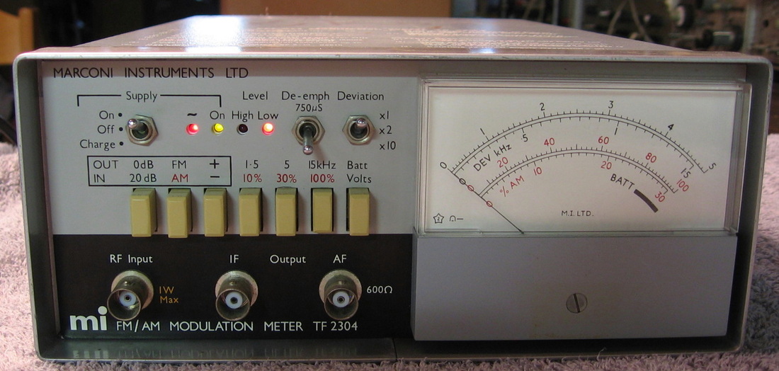
Marconi TF-2304: Modulation meter good to > 1 GHz, 150 kHz FM deviation. Meets the spec at full scale - the rest is a toss-up. I'm kind of disappointed with the accuracy which really does fall off on the lower ranges of the analog meter. ($CD) Grade: B-
This gave some really screwed up readings at first. The problem was traced to a microscopic little toroid, T1. It had been covered in some sort of protective goo which did a real nice job of hiding the fact that the wires had broken off. It was a pain to rewind the toroid, but it works now.
Postscript: Haven't used this very much, but the last time I did, the ON LED didn't light and the thing wouldn't lock to an incoming signal. Turns out that the ON LED went open and Marconi decided they would stupidly route voltage through the LED to the FM discriminator circuitry. New LED fixed all problems.
Postscript^2: One Sunday when I had absolutely nothing to do, I went searching for some piece that maybe didn't work anymore. Sure enough, you can always count on Marconi - the TF-2304 wouldn't lock to the incoming signal. Many hours later, I found the culprit: an ordinary 150K resistor that had opened up. Took me an afternoon to find which was the point of the whole exercise anyway.
Postscript^3: This is the piece that keeps on giving. One day after the Postscript^2 fix, I turned it on only to find the high/low level lights not working. A garden variety 741 op-amp was the culprit.
Postscript^4: And the saga continues... The unit seemed to be functioning, the IF and AF output were correct, but the meter readings were way off and didn't seem to respond much to a range change. I tapped on the main board and the meter swung wildly. I reseated the connector from the P/S to the board and all the problems disappeared.
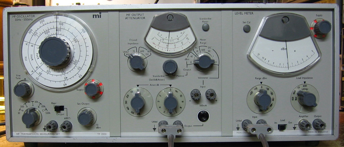
Marconi TF-2333: Called a transmission measuring set, it is really three discrete pieces bracketed together in one cabinet. The left piece is a 600 kHz sine wave generator, the middle piece is an attenuator and the right piece is an AC voltmeter. One would put a DUT between the output of the attenuator and the input of the voltmeter and measure the response. Kind of confusing attenuator knobology because you set the load impedance there and can also input a signal to its voltmeter. Not particularly accurate (~0.5 dB), but I dig the upside down meters. The front panel is also in excellent condition for a 35+ year old piece. (OM) Grade: B
This unit came wired for 230VAC with a 3-prong "British" plug. Converting it to 117VAC requires a fairly thorough disassembly and soldering new jumpers on the two independent transformers powering the sine wave generator and the voltmeter (the attenuator derives DC power from the sine wave generator). The voltmeter seems a bit noisy on the low amplitude ranges and the meter linearity isn't particularly good. I suspect one or more of the germanium transistors might be on their way out. I'll just wait until something becomes obvious.
Postscript: Many years later, I took a look at the noisy level meter (the right hand unit). I noticed that it was noisy only on certain amplitude ranges and the schematic showed that they didn't coincide with any funky switching in the amplifier sections. So I concluded that the range switch simply needed some cleaning. After a few sprays of cleaner, the noise is gone.
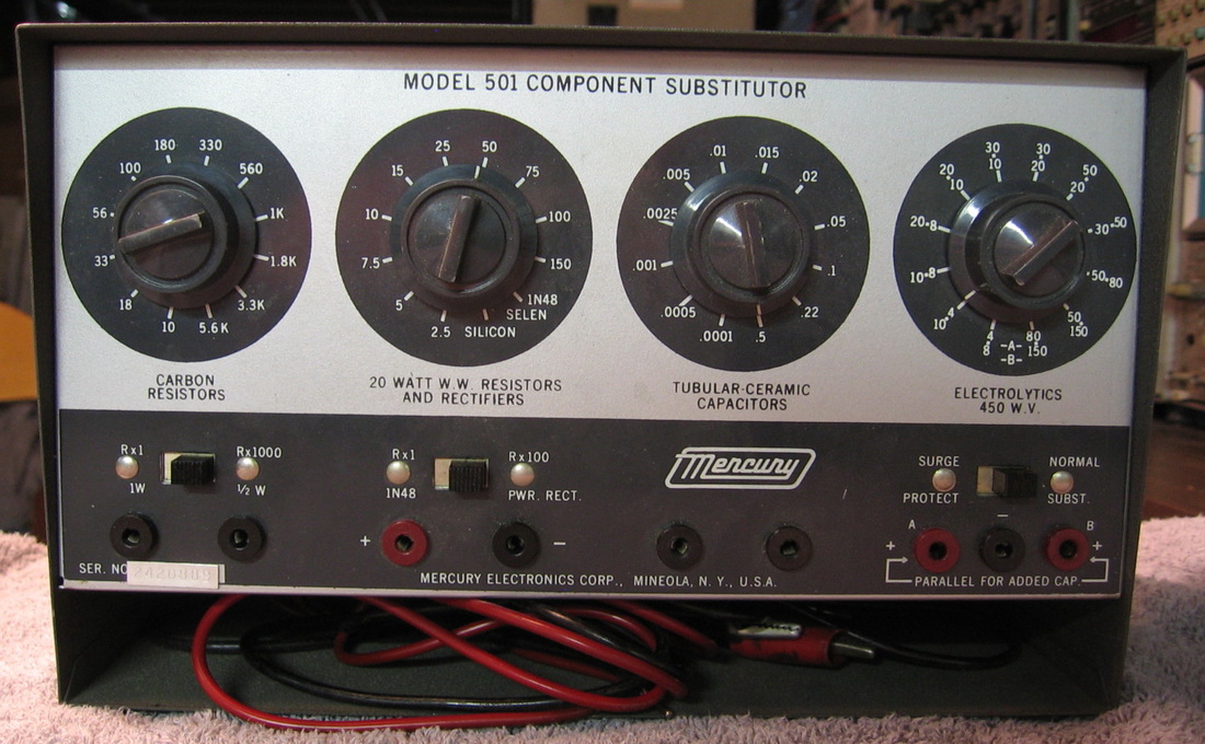
Mercury 501: A substitution box for the 1960's TV repairman. Has some 20W resistors inside that are useful at times. Even though I'm not a 1960's TV repairman, I use this quite a bit. (---) Grade: B
Needed all new electrolytic capacitors inside. The non-polarized caps and resistors all checked OK.
Needed all new electrolytic capacitors inside. The non-polarized caps and resistors all checked OK.
N/O : Nida, North Hills, Ono Sokki
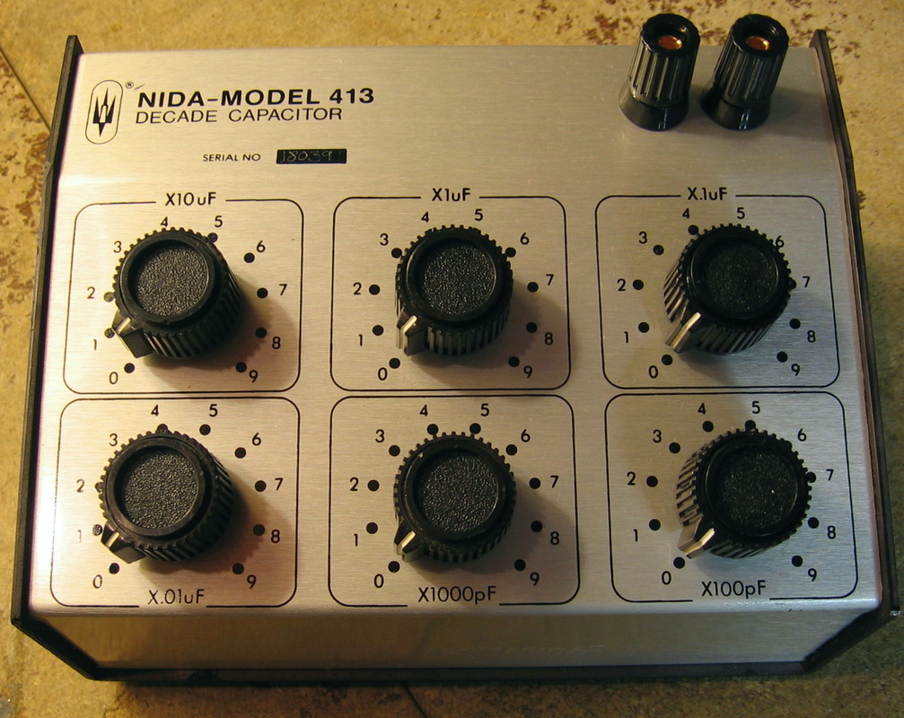
Nida 413: Decade capacitance box. Spans 6 decades with multipliers x100 pF, x1000 pF, ..., x1 uF, x10 uF. I measured the residual capacitance at 20 pF. Quality construction inside with 100V, 5% tolerance capacitors throughout. It's not quite clear how to determine the total accuracy of this unit. Suppose I dial in 100 pF and the thing is 100% off, giving me 200 pF. That's a horrendous error. However, suppose the 90 uF value is dead on. So if I dial in 90 uF + 100 pF, my 100% error becomes miniscule since it is dominated by the 90 uF. Therefore, what I did is measure the percentage error within each of the 6 decades for the nine possible values. I then looked at the total collection of 54 errors. The max error was 4.15% high and 3.2% low. The mean error was 1.28% and the sigma was 1.61%. All measured with my HP 4262A and who knows how accurate that is. But not too shabby. (--) Grade: A-

North Hills CS-152-7: Precision six-digit current source to 150 ma, 25 volts. Evidently, North Hills made this piece from about the mid-1960s to about 1990. The only manual I could purchase was for the early version and is dated 1966. Therefore, I have no idea what the specs are for my unit (built in 1989). Nor do I know what the "-7" suffix in the model number means. I know mine has an open circuit compliance of well past 40 volts, not the 25 volts listed in the manual. The accuracy spec is listed at "0.01% full scale" and that's about what I am seeing. The stability is listed as typically +/-2 ppm +/-1 nA. I haven't done a stability test, but it certainly looks rock solid on my Fluke 8502A DMM. The CS-152-7 has a modulation input jack on the back that allows the current to be (AM) modulated. It also has a (10 V) reference jack that either outputs the internal ovenized reference or allows you to supply an external 10 V reference (you then must set the front panel output switch to 0). All in all, a real nice addition to my other calibrators and a fairly good buy at $75. (OM) Grade: A-
The seller did not offer any description of the condition other than it needed a new (captive) power cord. Which it certainly did and which it certainly got. When you open up this piece, however, it is somewhat disconcerting since the power cord doesn't seem to go to a main transformer; the wires just disappear into a big harness. In fact, there isn't any main transformer to be found! The piece consists basically of five modules, basically all sealed in their own metal containers: 1) voltage reference (ovenized), 2) range resistors (ovenized), 3) K-V divider, 4) preamp, and 5) power amp. Except for the K-V divider, the modules all need power and they all get it by a dedicated power supply that is contained within it. Anyway, back to the repairs. All of the switches were noisy and the initial current readings therefore were also. The output switch is particularly important because the internal voltage reference goes through it. After a thorough cleaning, things looked good except for two of the three neon lamps on the front panel which were marginal (new ones are on order). As far as calibration, the 1965 manual says there are adjustments for the 10 V reference and the zero current offset. So I found the analogous two pots on my somewhat different unit and the CS-152-7 adjusted nicely.
Postscript: The output switch was still a bit noisy, so I decided to replace it at the same time I replaced the three neon bulbs. It is a 2-pole, 3-throw rotary switch and I replaced it with a 4-pole, 3-throw rotary switch, doubling up each contact. Hopefully this will keep the switch resistance low and stable over the years. It looks as though about 1 ma comes off of the 10 V reference and through the switch. I estimate the parallel contact resistance of the switch would drift no more than 25 milliohms. So the switch could drop 25 uV which is an acceptable 2.5 ppm error at 10 volts.
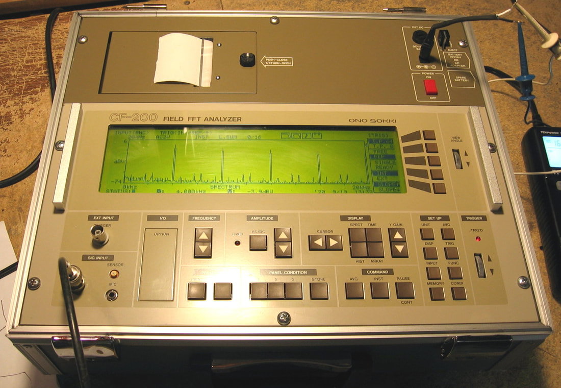
Ono Sokki CF-200: Portable FFT Analyzer. This piece basically performs a 1024-point FFT over a maximum 0 - 20 kHz band. Presumably it was manufactured by Ono Sokki to do audio and vibration measurements. In some sense, it is a very watered-down version of my HP 3562A or HP 35665 Dynamic Signal Analyzers. However, in addition to being highly portable (it sits in its own little suitcase), it is designed to run of a 12V, 2A sealed lead acid rechargeable battery. Fortunately, it has an external 11.5 - 30 VDC input jack, because the battery is long gone. Without any documentation whatsoever, here is what I can ascertain about this unit. The selectable amplitude scale goes from 10 V to 500 uV. The upper frequency limit can be set from 20 kHz down to 1 Hz. The displayed noise floor (50 ohm termination on input) is about -124 dBVr and -147 dBVr at 20 kHz and 1 Hz bandwidths respectively. A maximum of 80 dB can be shown on the y-axis. The CF-200 has four different displays: 1) spectrum, 2) histogram, 3) time, or 4) waterfall. There are selections for a anti-aliasing pre-filter on the A/D converter, Hanning or Rectangular waveforms, and some triggering and cursor functions too. There is a built-in thermal printer and the unit draws about 6 watts when running (15 V at 0.39 A). Ono Sokki still manufactures these FFT analyzers, albeit now with a much more modern design and much more capability. But for what it "advertises," the CF-200 works quite nicely. One can argue that the same functionality can be achieved with the sound card in a laptop running a freeware FFT program. But most sound cards that I've seen do not have a flat frequency response especially below 50 Hz where they roll off considerably. All in all, a good buy at $14. (--) Grade: A-
The battery was completely dead upon receipt. I cut it open with a Dremel tool and all the cells had turned to powder. There is no part number on the battery case so there is probably no hope of ever getting a replacement (unless I make my own). No worries, I'll just power it up externally (my TekPower TP3016M portable power supply makes a good companion). When I did power it up, the unit performed flawlessly. In fact, judging from the overall cosmetic condition (10 out of 10) and the lack of any wear on the BNC jacks, I would say that this unit had hardly ever been used. I did pull the chassis out of the suitcase and confirmed that the construction is first-rate.
The battery was completely dead upon receipt. I cut it open with a Dremel tool and all the cells had turned to powder. There is no part number on the battery case so there is probably no hope of ever getting a replacement (unless I make my own). No worries, I'll just power it up externally (my TekPower TP3016M portable power supply makes a good companion). When I did power it up, the unit performed flawlessly. In fact, judging from the overall cosmetic condition (10 out of 10) and the lack of any wear on the BNC jacks, I would say that this unit had hardly ever been used. I did pull the chassis out of the suitcase and confirmed that the construction is first-rate.
P : Pacific Measurements, PDI, Peak, Philips, Power Designs, PowerMate, Princeton Applied Research
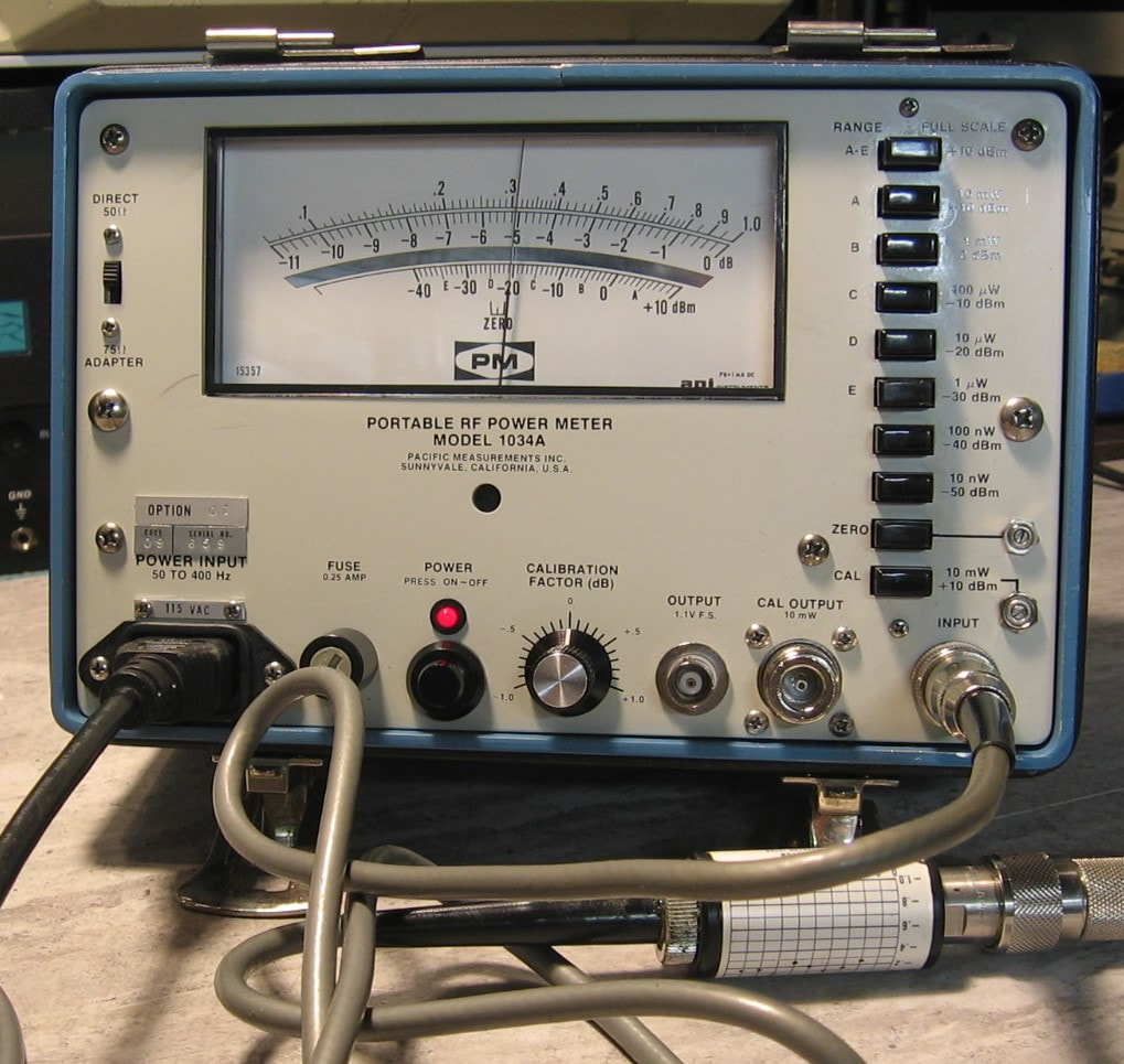
Pacific Measurements 1034A: RF power meter with sensor covering 1 MHz to 18 GHz over the range of +10 dBm to -40 dBm (full scale). Anybody who buys vintage test equipment on eBay will notice that at any given day, there are dozens and dozens of RF power meters up for sale. They are usually very cheap (<$50) and that is because none of them have the required sensor/probe. Occasionally you will see the matching sensor for sale in a different auction for several hundred dollars. Therefore, I was surprised to see the Pacific Measurements 1034A with the sensor for only $50 and I snapped it up immediately. It's easy to use, has a built-in calibrator and zero function and seems accurate on all ranges. Down around -50 dBm, there is a little meter jitter, but I suppose that is to be expected. The 1034A is also sold as the Wavetek 1034A and that's where I found the service manual (although a person on one of the forums remarked that the boards are different between the two units even though the front panels are identical). Mine has Option 1, internal batteries, but fortunately the previous owner had removed the batteries before they could leak all over the insides. (PDF) Grade: A-
Sold as "intermittent," the problem was clearly the front panel range selection pushbuttons. The switches are sealed, but I was able to pry up on the plastic switch case enough to squirt contact cleaner into the gap. I don't know how long this will last, but I suppose in a pinch, I can replace the switches once I figure out how the interlock mechanism works. For batteries, the only information I could find was on the schematic where it was labeled 6.7V. So I wired up 5 alkaline C-cells with a 1N4001 diode to prevent charging. I measured the current drain when the unit is operating as about 200 ma, so I will get a fair amount of time if and when I use the 1034A on battery power.
Sold as "intermittent," the problem was clearly the front panel range selection pushbuttons. The switches are sealed, but I was able to pry up on the plastic switch case enough to squirt contact cleaner into the gap. I don't know how long this will last, but I suppose in a pinch, I can replace the switches once I figure out how the interlock mechanism works. For batteries, the only information I could find was on the schematic where it was labeled 6.7V. So I wired up 5 alkaline C-cells with a 1N4001 diode to prevent charging. I measured the current drain when the unit is operating as about 200 ma, so I will get a fair amount of time if and when I use the 1034A on battery power.
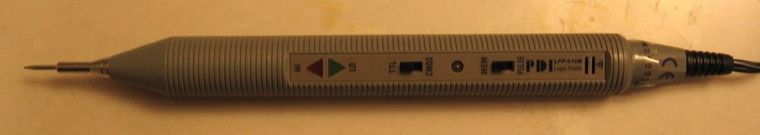
PDI LPP-610B: I have no idea who PDI is and it really doesn't matter as this identical logic probe is available from many different vendors. Its two LEDs will show seven different logic levels and/or pulse rates. Also emits high and low tones in case you are blind. Now let's contrast this with the HP 545A logic probe which has one red LED that is either off (low), bright (high) or just a hair less than bright (tri-state or something else). Admittedly, the HP unit does 80 MHz and the LPP-610B only goes to 20 MHz. But the HP 545A costs several hundred dollars and this generic Taiwanese model is still less than twenty bucks. (OM) Grade: A-
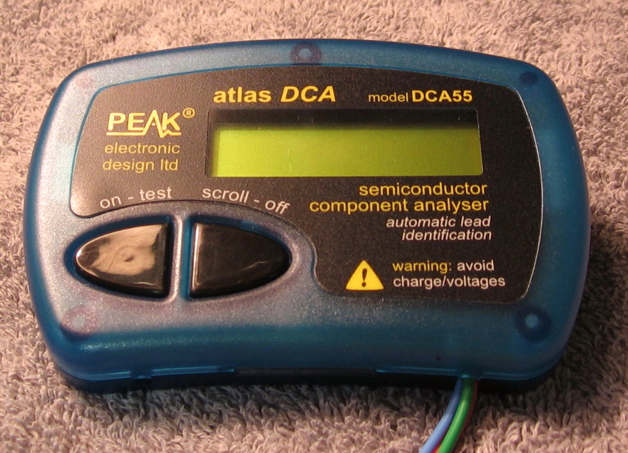
Peak DCA55: Unfortunately this unit only works out-of-circuit. Hook it up to virtually any semiconductor and you get a scrolling readout of who, what, where, and why. This is a great device for identifying components in your junkbox. It really gets quite confused if you hook it up to a device in-circuit. (OM) Grade: A-

Peak ESR60: This unit does work in-circuit and measures the C and ESR of electrolytics at the industry standard 100 kHz. Also can serve as a milliohmmeter for measuring board traces. I know ESR seems to be the rage these days, but I don't think I ever found a capacitor whose capacitance was in spec yet the ESR was too high. Either the cap is good or the cap is hosed. But at least this does in-circuit testing and is quite useful. The unit came with alligator clips which I couldn't stand. I wrote to Peak and asked them if there was any problem with me replacing the leads with minigrabbers. They wrote back and basically said "we wish we had thought of that." (OM) Grade: A
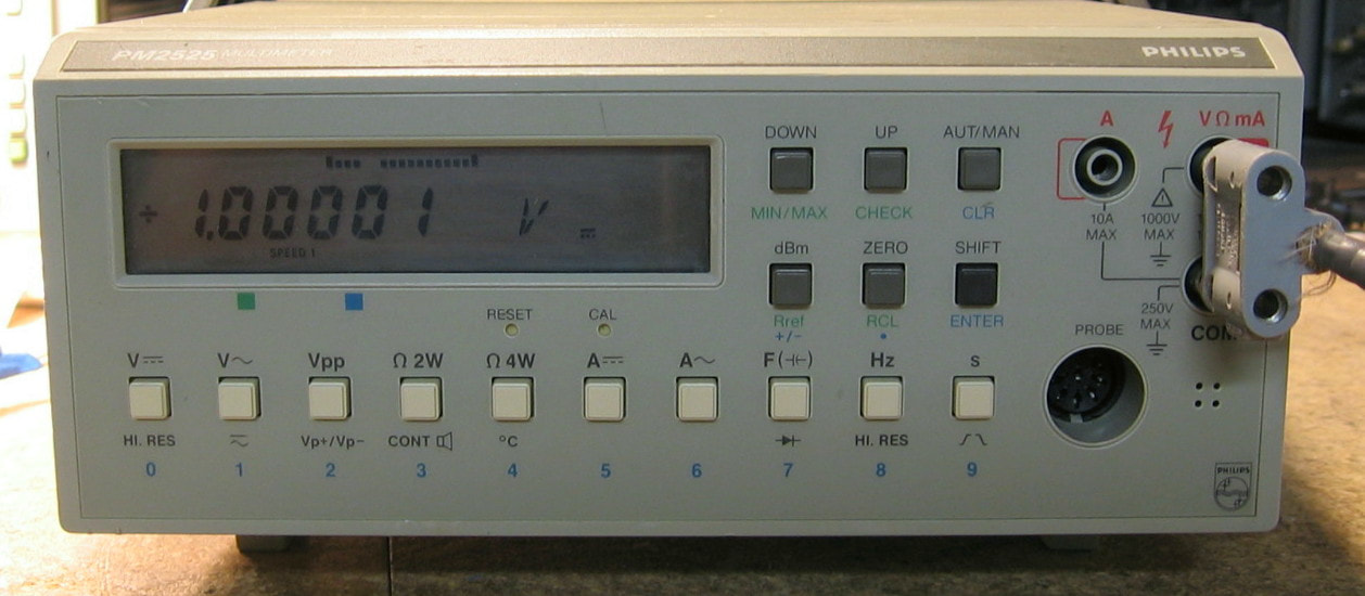
Philips PM2525: 5-1/2 digit DMM. Well, it mostly is a 4-1/2 digit DMM, but it can be coerced into 5-1/2 digits in some functions and ranges. On the positive side, it will do a lot, namely DCV, ACV, peak V, DCI, ACI, ohms (2W and 4W), frequency, capacitance, continuity, diodes, and probably a few more I've missed. But that's about all I can say positively about the 2525. Now for the negatives! First of all, one look at the picture and you will see that the (non back-lit) display is almost impossible to see unless the lighting is perfect. Moreover, Philips put the on/off switch on the back - there should be a law against that. The specs are horrendous, for example, 0.02% reading + 0.01% range on the most accurate DCV range with a response time of 6 seconds no less! Also, four wire ohms can only be done through the probe socket. But I've saved the best negative for last, for when you press a front panel button to change a function (or range), it turns on a motor that rotates an internal function switch - a rotary switch just like you would find in a handheld DMM. This piece deserves to win the Nobel prize for stupidity. (PDF) Grade: C
As received, the unit basically worked. But I'm pretty sure an internal part of the motor has broken and is rattling around inside the motor case. So I'm not too optimistic in the long term and will start looking around for a cheap DC motor that will fit.
Postscript: I was fooling around with the PM2525 one day because it seemed like it was out of spec. Moreover, with a shorted input, the thing was drifting all over the place between +/-10 mVDC. I spent three or four days with futile attempts at debug, but the full schematics are nowhere to be found (even from a copy purchased from a manual dealer). Finally, I pulled the battery backed-up RAM and that cleared the stored calibration constants. BIG mistake! Indeed, Philips requires you to completely calibrate the unit twice - cold and hot - in order to get rid of the annoying "NC" (not calibrated) message that is now permanently affixed to the end of every reading in every mode. The cold calibration is difficult enough, but they want the hot calibration to be done at 90 - 105 degF and suggest you throw it into an oven for an hour or so. I don't think they are kidding because it seems like Philips is reading the internal temperature (via a transistor) and so will fail all attempts at the hot calibration unless it really is at the right temperature??? Preposterous if so. One might argue such a comprehensive calibration might be required for a very accurate meter. But the PM2525 has terrible specs and if they can't get 0.02% DCV accuracy with a simple calibration (zero and full-scale), something is wrong with them. Anyway, I spent another three or four days trying at least to calibrate the DCV function to no avail. Finally, I simply let the thing run for about 12 hours. Seemed much better behaved, with only a few tens of uV offset, and I was ultimately able to calibrate the DCV (cold and hot without changing the temperature). I may get around to the other functions one day, but I really have no intentions of ever using this piece.
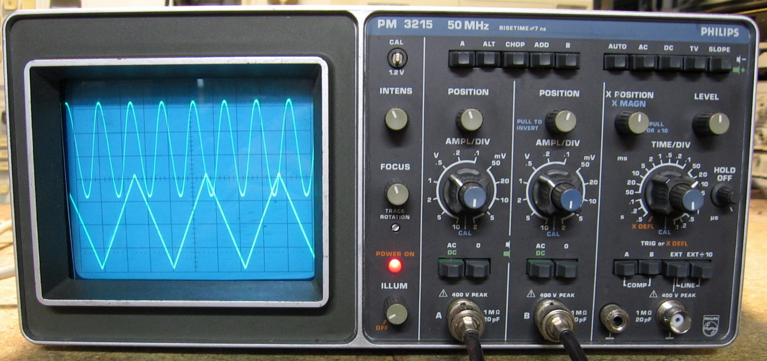
Philips PM3215: 50 MHz analog oscilloscope. The PM3215 is basic dual-channel scope suitable for the beginner. None of that fancy delayed timebase stuff to worry about. It does have one fancy feature, namely composite triggering. When both the A- and B- channel trigger buttons are depressed, the scope will trigger alternately on each channel. That allows you to get a simultaneous display of two different waveforms regardless of any frequency difference between them (see photo for an example). This seems different than the usual ALT function on most of my other scopes. Philips made a lot of PM32xx scopes in the 1980s. Many of them suffer from power supply problems (the transformer in the switching supply), but mine seems to have survived. Not a great buy at $55, but it did include two very nice 50 MHz BK Precision probes, which was unexpected. (PDF) Grade: B+
The photo from the seller showed a trace, so I took a chance. The first thing I did when I received the unit was replace the Rifa capacitor hanging off the AC receptacle. Then I checked the P/S filter caps for shorts (none found). Only then did I power the unit up. Checking the DC voltages, however, required me to remove the cabinet. Unfortunately, the cabinet had so many dents in it that I couldn't pull the scope out of it. I finally had to pop the rivets in the cabinet and peel the cabinet away. Electrically, the scope was fine, although it did need the usual spritz of cleaner in the switches. The timebase was mildly out of calibration, but adjusted correctly. The unit needs two 28V, 40ma bulbs for the graticule illumination and a new blue display filter. Maybe some day. The power cord was also frayed where it entered the back panel, so it was replaced. Finally, I banged out all the dents and reassembled the cabinet with screws. Funny that I had to do the same thing with the only other Philips scope I have, the Fluke/Philips PM3390B. Must be something about Philips cabinets that attract dents.
Postscript: Turned this on one day and ... absolutely nothing. Pulled the back panel off which contains the AC transformer and line voltage select switch and nothing was coming out of the secondary of the transformer. Philips put in a thermal fuse gizmo on the primary and that tested open. Only the wire of the fuse is made to be replaceable and good luck finding one. So I simply jumped it with a thin piece of wire. No thermal protection anymore, but I can live with that. If I ever get around to it, I might jam a normal thermal fuse in there, but honestly, I don't think I will be using this scope very often.
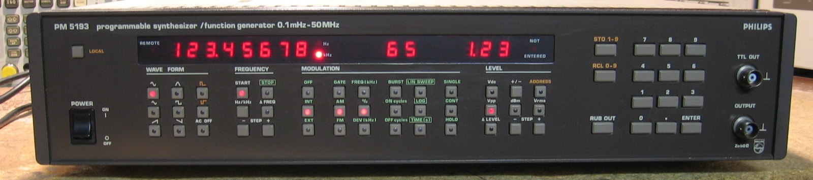
Philips PM5193: 50 MHz synthesizer/function generator. This is a somewhat odd piece that generates sine, triangle, square, haversine, sawtooth and pulse waveforms. The PM5193 uses a DDS with a waveform lookup table for frequencies up to about 2.1 MHz; higher frequencies use a VCO/PLL with various waveform shapers. It will do 50 MHz for sine and pulses; the other waveforms are derated down to as little as 20 kHz. It also has internal AM and FM modulation capabilities as well as provisions to generate burst waveforms and to do frequency sweeps. So the PM5193 is actually quite a capable little piece. The specifications, however, are strictly middle-of-the-road and are somewhat disappointing given the look and feel of the piece. I suspect the PM5193 may comfortably beat these mediocre specs, but I'm not going to run through and measure them all. Similarly, the man-machine-interface is a bit awkward, but easy to navigate once you get used to it. The build quality is very good and so is the serviceability for the most part. I'll go out on a limb and give it a slightly higher grade only because it probably is better than Philips advertised. (PDF) Grade: A-
The photo from the seller showed the unit powering up with Error #3, but made no other claims about the working status. Error #3 simply means the 3V Lithium coin cell battery that keeps alive the RAM storing user configurations is dead. So a new battery fixed that and the 5193 booted up nicely. However, the waveforms were way too low in amplitude and the negative sides severely clipped. That usually means one of the two push-pull output transistors is bad. But before looking there, I heeded my own advice which says to always check the power supplies. Indeed the 20V was fine, but the -20V read about -1.6V. There is a 5.6 ohm current limiting resistor on the output of the -20V supply's pass transistor and the resistor had migrated to about 70 Kohms. This forced the 4-terminal adjustable regulator controlling the pass transistor basically to shut down. A new 5.1 ohm, 5-watt resistor from my junkbox fixed all ills. I ran through the ~80 step calibration procedure which looks a bit daunting until you realize that all the adjustment pots can be reached through holes drilled in the bottom of the board. Nevertheless, most of the pots had dead spots where they had been sitting for 30 years, but fortunately the unit was out of adjustment and the pots needed a little bit of rotation.
The photo from the seller showed the unit powering up with Error #3, but made no other claims about the working status. Error #3 simply means the 3V Lithium coin cell battery that keeps alive the RAM storing user configurations is dead. So a new battery fixed that and the 5193 booted up nicely. However, the waveforms were way too low in amplitude and the negative sides severely clipped. That usually means one of the two push-pull output transistors is bad. But before looking there, I heeded my own advice which says to always check the power supplies. Indeed the 20V was fine, but the -20V read about -1.6V. There is a 5.6 ohm current limiting resistor on the output of the -20V supply's pass transistor and the resistor had migrated to about 70 Kohms. This forced the 4-terminal adjustable regulator controlling the pass transistor basically to shut down. A new 5.1 ohm, 5-watt resistor from my junkbox fixed all ills. I ran through the ~80 step calibration procedure which looks a bit daunting until you realize that all the adjustment pots can be reached through holes drilled in the bottom of the board. Nevertheless, most of the pots had dead spots where they had been sitting for 30 years, but fortunately the unit was out of adjustment and the pots needed a little bit of rotation.
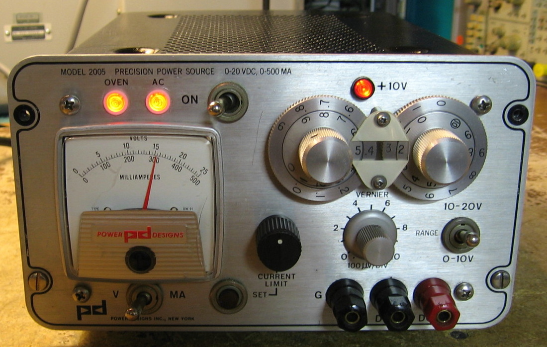
Power Designs 2005: "A general purpose power supply with the accuracy of a precision calibrator," so says the manual. Well, maybe by 1963 standards, but the "calibrator" accuracy is only 0.1% which is pretty anemic nowadays. This single output supply will do 20 volts at 500 ma with a four digit dial selection and additional resolution provided by a vernier pot. A nice feature on the 2005 that I wish all power supplies had is a front panel button to short the output so you can adjust the current limit. Sure beats fumbling around with the leads. The interesting thing about this piece is that the critical elements of the regulator are encased in a thermostatically controlled oven. This provides a basic stability of 0.001% and an excursion of less than one millivolt per week, all with an advertised ripple of 100 microvolts peak-to-peak. The 2005, and its follow-on 2005A, have achieved cult status among tinkerers because the ripple and stability specs are better than most supplies being built today. (PDF) Grade: A-
Offered by the seller as working, it almost was when I received it. The panel neon light for the oven heater stayed off when I first powered it up, but the oven was getting warm and putting a voltmeter across the heater pins proved that eventually it started to cycle on/off properly. So the scare of a faulty oven was squashed. Being almost 50 years old, all of the switches needed the normal shot of tuner cleaner. All was going according to plan until I tried to verify the ripple spec on my HP 3400A RMS voltmeter. As the voltage was turned up, the 3400A meter pegged. Hooking the 2005 up to the scope revealed a 1.2 MHz sine wave at several hundred millivolts peak-to-peak. So I took a small capacitor, one end to ground, and starting touching the component leads. Eventually I settled upon a capacitor across base-collector of Q4, a PNP in the regulator feedback loop. Meanwhile, the three main electrolytic capacitors seemed a bit too warm for me, so I decided to replace all the electrolytics in the unit. There were two additional capacitors listed in the addendum to the manual (not shown in the schematic) that I also added. Even after all the new caps, there was still a small 1.2 MHz signal without my cap across Q4, so it shall remain in the circuit. Also, the calibration procedure calls for adjusting two pots - a 0V pot and a 20V pot. However, I was unable to get the 2005 properly adjusted, particularly in the 10 to 20V range. And that is because the voltage selection switches really only generate intermediate voltages between 0 and 10V; they add an additional 10V (1 ma through a precision 10K resistor) to bring it up to the 10 to 20V range. If that 10K resistor is off, calibrating it solely at 20V is guaranteed to screw either the 0-10V or 10-20V range, take your pick. What they really should have done is add a trimmer to the 10K resistor and let you first calibrate it at 10V and then use the trimmer to translate that calibrated range into 10-20V. And so that is what I did. Now I am comfortably achieving a maximum voltage error of 0.05% (against the 0.1% spec) with most voltages only off by about 0.02%. I was never able to achieve the 100 uVp-p ripple spec, however. I am getting about 200 uVrms and the peak-to-peak looks to be something around 500 uV. Some of that may be due to my lack of proper instrumentation; a correct measurement of power supply ripple has to be done with proper cabling, proper terminations, and at a specified bandwidth. Quite frankly, I find the spec a bit suspicious since no bandwidth is mentioned and I doubt they had the equipment to measure it properly in 1963. Finally, two new neon bulbs, a new current limit knob and a repaint of the cover rounded out the repairs on this one.
Postscript: Well, it really annoyed me that the ripple wasn't meeting the 100 uVp-p spec. Obsessive-compulsive you say? I prefer to call it "persistent." I removed my 0.1 uF cap and hooked up a capacitor substitution box. Just the placement of the leads made a huge difference in the stability of the power supply. So figuring that shorter is better, I changed the capacitor to 0.022 uF and soldered it right across Q4 with about 1/16" leads. The ripple is now Gone with a capital G. In fact, it is pretty much unmeasurable on any of my AC voltmeters and can't be seen on any of my scopes.
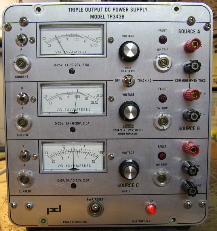
Power Designs TP343B: Triple output power supply, providing [email protected] on the upper two supplies and 6V@5A on the bottom supply. All three are rated to higher voltages at the expense of lower current. The upper two supplies can either be set to independent or tracking. A very curious design that switches pass transistors around at higher voltages (hence the lower current ratings). Makes no sense to me why they did it that way (unless it was to lower the power dissipation of the transistors). Volt and amp metering, current limit adjustments and overvoltage adjustments. The voltage knobs control 10-turn pots which are good for precision, but real annoying to adjust. Big and hefty. (PDF) Grade: A-
Advertised by the seller as "A supply works OK, B supply only reaches 18V, and C supply starts up and then shuts down." And that is exactly what I received. The C supply fault was traced to a defective bridge rectifier (2 open diodes) that actually shut down the negative portion of the following split supply and charged the electrolytics with the wrong polarity. Not surprising that the bridge blew, since the previous repairman put in an underrated part. The B supply fault was traced to a faulty voltage reference, but it abruptly fixed itself as I was poking around. There was also a shorted 5V Zener diode in the A supply that provides the negative rail of an op-amp. This was replaced with a 4V junkbox zener - close enough, the op-amp doesn't need to output negative voltages anyway.
Postscript: Pureness of body and mind would dictate that the 4V junkbox zener be removed and replaced with the proper value. And so it was.

Power Mate Lectra-Load LL-300B: Dynamic load good to 1250 watts, 300 amps and 50 volts (not at the same time, of course). Both static and pulsed loading are available. It's pretty much punch the range button and turn the knob for the desired current. Very little bells and whistles are included. There are three amp/volt ranges (so the unit acts like a constant resistor) and a single 0-300A constant current mode (not dependent on source voltage). The only thing I really don't like are the potentiometers which are single turn, but have a reduction gear built into them; this gear, however, does not stop at the end of the pot travel - it simply keeps turning forever. So you have to watch the display to see when you've hit zero. A fairly simple design consisting of a small op-amp based control section, a mosfet pre-driver, a pair of driver power transistors and 36 (count 'em!) power transistors for the actual load. The 36 transistors are split across four thick copper sheets with aluminum fins. Air is blown by two high speed fans and the LL-300B sounds about as loud as a Boeing 737. There are also two bad-ass relays to handle the red "short circuit" button on the right of the front panel which potentially could put 300 amps through them. Build quality is moderately good, but somewhat inconsistent. There are places where it looks way over-designed and places where it looks very amateurish. (PDF) Grade: B
Hey, how could I pass this up for 25 bucks? The seller claimed that there was something wrong with the pushbutton switches and claimed things got better when he squirted tuner cleaner into them. That may be, but seeing as the thing drew no current regardless of knob settings and then suddenly went to max current as soon as the input voltage hit about 12 volts (again, regardless of knob settings), I thought otherwise. I pulled the two driver power transistors (arranged in parallel) and one of them tested good, but with a very low beta. So I think that one is on the way out. But the other one's beta was fine, so that was not the ultimate cause of my problems. I replaced various op-amps and comparators on the control board, but that had no effect either. About the only part left to check was the 2N6661 driver mosfet. I pulled it and my Peak Component Tester said "no component found." I replaced it with an IRF630 I found in the junkbox and the LL-300B sprang to life and acted properly. At least I thought it did until I noticed that the load current from my source HP 6034A (set to 10V, 10A) was gyrating randomly. I started shaking wiring harnesses in the LL-300B and one of them was definitely the cause. Resoldered the multi-pin connector to the board and now everything is stable. All in all, a good fix given that the service manual is nowhere to be found.
Postscript: A few years later, a very kind person in Brazil sent me a pdf of the op/svc manual.
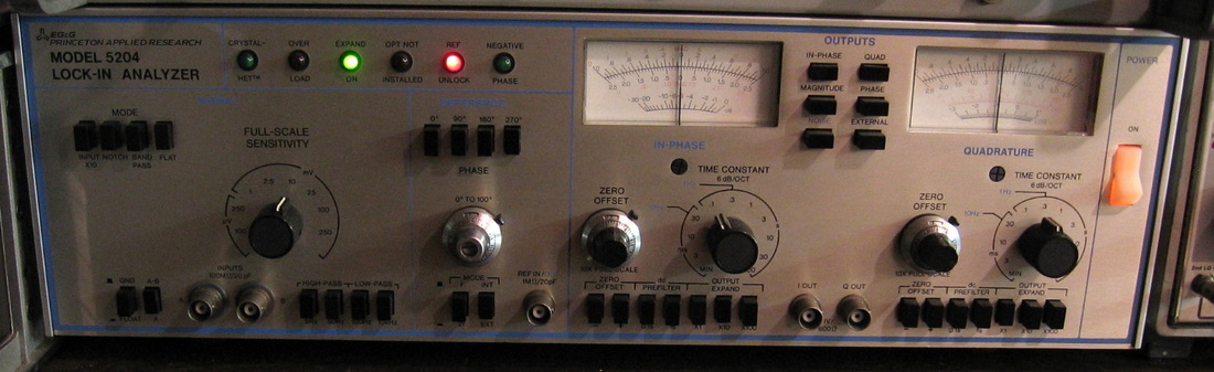
Princeton Applied Research 5204: A lock-in amplifier which essentially performs a very narrow single-point Fourier transform. Can pull out a sub uV signal in the presence of many volts of noise. Lock-in amplifiers seem like some sort of magic to the optical processing crowd. To me, it's just a phase coherent detector with a very narrow filter. This is Signal Processing-101. Of limited use because you have to supply the phase coherent reference. (---) Grade: C+
R : Racal, Radio Shack, RCA, Rigol, RLC, Rotek

Racal 14DS: Fourteen channel (plus voice) instrumentation recorder from the mid-80's. Currently being fed with VHS tape. Everybody needs a 14 channel instrumentation recorder, right? This thing must have cost upwards of $50K when new. It works great providing you can find 1/2" instrumentation tape at a reasonable price. I couldn't. (OM) Grade: B+
What a beast! Had to manufacture my own take-up reel and had to have the capstan re-rubberized. There were faulty CD4011 and CD4013s on channel 14's record board.
Postscript: The tape transport mechanism uses two mechanical arms to measure tape tension and feeds back the imbalance to the spool motor drivers. These arms operate on oil-filled bearings to provide dampening. On my unit, the oil had leaked out of one of the arms and despite all efforts to fill it back up, the arm exhibited no dampening. This caused the tape transport to suddenly stop once in a while during rewind or fast-forward. About a year after I bought the 14DS, I saw a "parts unit" for sale on eBay. It was basically complete except for some of the cabinet parts. The price? A mere 99 cents (plus shipping). Now my tension arms operate like they should. Plus I now have three boxes full of spare motors, spare circuit boards and miscellaneous switches and other mechanical parts. Is this a great country, or what?
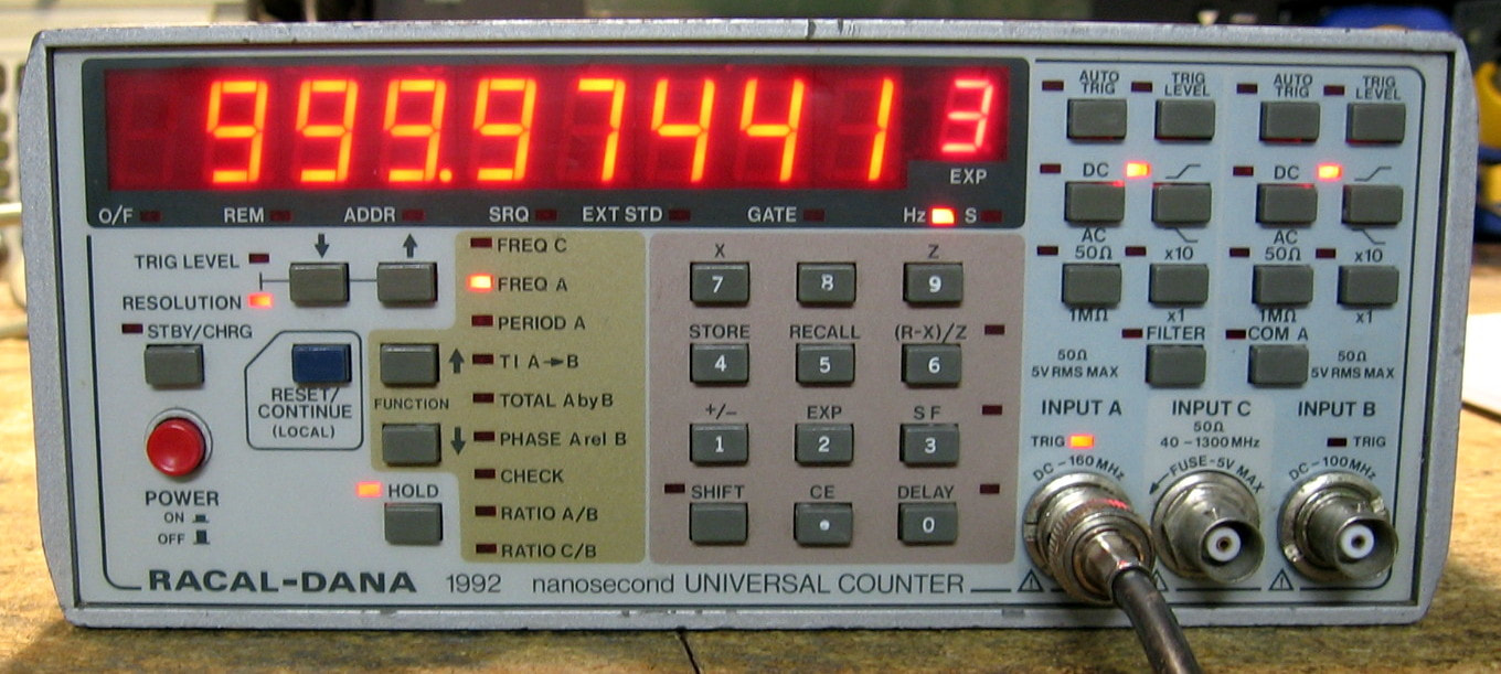
Racal 1992: Basic multi-function counter to 160 MHz. Mine has the optional C-channel (pre-scaler) good to 1.3 GHz and the ovenized oscillator (the better high stability one). Pretty straightforward except to put it in and out of standby (so the oven still works), you leave the power switch on, but press the standby button on the front panel. Has a very large, bright 9-digit display with exponent. The Racal counters (1991/1992, etc.) are known to develop faulty front panel switches over time. There are several youTube videos showing how to replace them with switches that are close in form factor. I even bought a bunch from Mouser before the piece arrived. But in my unit, all the switches seem to work just fine. The main counting chip is a special Racal hybrid (unobtainable) and it runs really hot (>60 degC), risking an eventual burn-out and the death of the counter. I'm going to stick on a couple of heat sinks before I run this piece for any appreciable time (PDF) Grade: A-.
Picked this up for $50 because I needed something to fix. The seller's photo showed the unit powered up with only a single LED lit above the B-channel input. And that's how I received it. It was quickly clear that the microprocessor was not being supplied the reset signal which consists of 0V for 300 msec, then jumping up to a constant 5V. This was traced to a faulty transistor inside a five-transistor CA3083 array. I jumped over the one transistor in question and the 1992 started right up. But it only displayed "1992" and then hung. It looked like the keyboard signals were not being properly reset after reading, so I went on a wild goose chase after that. Turns out that several of the transistors in the CA3083 are used for the reset signal and jumpering over one wasn't quite good enough. Indeed, after the reset signal popped up to 5V, it went right back down to 0V keeping the microprocessor in continuous reset. I didn't have a CA3083, so I simply removed the chip and soldered in a bunch of 2N3904 transistors. Works fine. There also was a burned out LED on the front panel that I replaced.
Postscript: The bad reputation of the front panel switches is confirmed unfortunately. One day, I noticed that several of the buttons were unresponsive. A quick check on the ohmmeter showed them to be about 3 Kohms when closed. I took the front panel apart and flooded all the switches with contact cleaner. Big mistake. That pretty much killed all the switches (I'm really not sure why, however). So I used my set of replacement switches and spent four hours replacing them all.
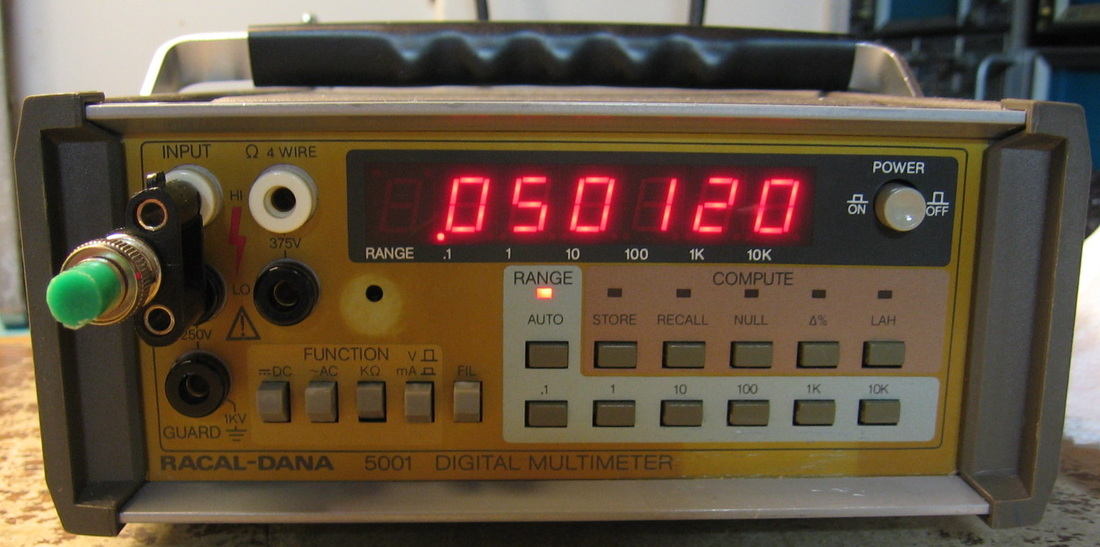
Racal 5001: Standard issue 5-1/2 digit DMM. Not particularly accurate. Not particularly fast. About on par with my HP 3468B DMM. Does have a few useful math functions like null, min, max and average. The service manual, however, is extremely well done. Not that I needed it, because despite being offered on eBay as broken, it worked fine after a shot of tuner cleaner into the function switches. Some day I am going to return one of these pieces to the seller with a note saying, "Your description of the unit said that it was broken and required repair. Upon receipt, however, the unit was functioning correctly. Please refund my money." ($CD) Grade: C
Move along Johnny, nothing to see here.
Move along Johnny, nothing to see here.
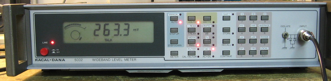
Racal 5002: Broadband AC voltmeter. 5 Hz to 20 MHz range with an astonishing 30 uV to 316 V range - that's 140 dB! Measures DC, true RMS AC, true RMS AC+DC, positive peak, negative peak, mean, peak-to-peak, averaged peak, peak-hold, crest factor, form factor and averaged scaled to RMS sinewave. Basic 4 digit LCD display with a curious dual "analog" meter on the left. The upper scale shows the percentage of the full scale range and the lower circle is at x10 resolution. The best case accuracy is about 0.5% of reading + 0.5% of range. A nice feature of the unit is its ability to display volts, watts or dBm with a push of a button. Has some hidden menu items that control filtering, averaging time, etc., and can store/recall 12 configurations. Mine also has the GPIB option. While the 5002 looks like a piece from the late seventies, the chip date codes show it was built in 1990. So much for modern European design. But I have to agree with the 1985 Racal catalog where they say "The model 5002 is the most versatile wideband AC voltmeter available." (PDF) Grade: A
The eBay listing photo showed a blank LCD display and none of the front panel LEDs lit except for the power-on LED. After studying the schematic, I was sure the problem was in one of the 1:8 decoder ICs. But, alas, probing with a scope showed every IC, from the 6802 uP through to the LCD display, was happily toggling bits. While I was pondering that, I removed the dead 3.6V lithium battery used to backup the RAM. On a lark, I attached an external P/S to the battery terminals and fired the 5002 up. Worked flawlessly. Evidently, the battery voltage goes through a comparator to develop a logic signal that disappears into the uP circuitry. So Racal must have designed it so that it simply will not work without a proper battery voltage. Kind of surprising because the worst thing that could of happened is that the user would lose some pre-stored configurations - not a deal killer in my opinion. Anyway, I replaced the 3.6V lithium with two alkaline AAs. The unit passes the functional checks but I tweaked all of the cal pots just because I could. Cosmetically, this piece was very nice. It had all four feet, the tilt-up bail and the two pull-out instruction sheets. That's certainly a rarity off of eBay.
The eBay listing photo showed a blank LCD display and none of the front panel LEDs lit except for the power-on LED. After studying the schematic, I was sure the problem was in one of the 1:8 decoder ICs. But, alas, probing with a scope showed every IC, from the 6802 uP through to the LCD display, was happily toggling bits. While I was pondering that, I removed the dead 3.6V lithium battery used to backup the RAM. On a lark, I attached an external P/S to the battery terminals and fired the 5002 up. Worked flawlessly. Evidently, the battery voltage goes through a comparator to develop a logic signal that disappears into the uP circuitry. So Racal must have designed it so that it simply will not work without a proper battery voltage. Kind of surprising because the worst thing that could of happened is that the user would lose some pre-stored configurations - not a deal killer in my opinion. Anyway, I replaced the 3.6V lithium with two alkaline AAs. The unit passes the functional checks but I tweaked all of the cal pots just because I could. Cosmetically, this piece was very nice. It had all four feet, the tilt-up bail and the two pull-out instruction sheets. That's certainly a rarity off of eBay.
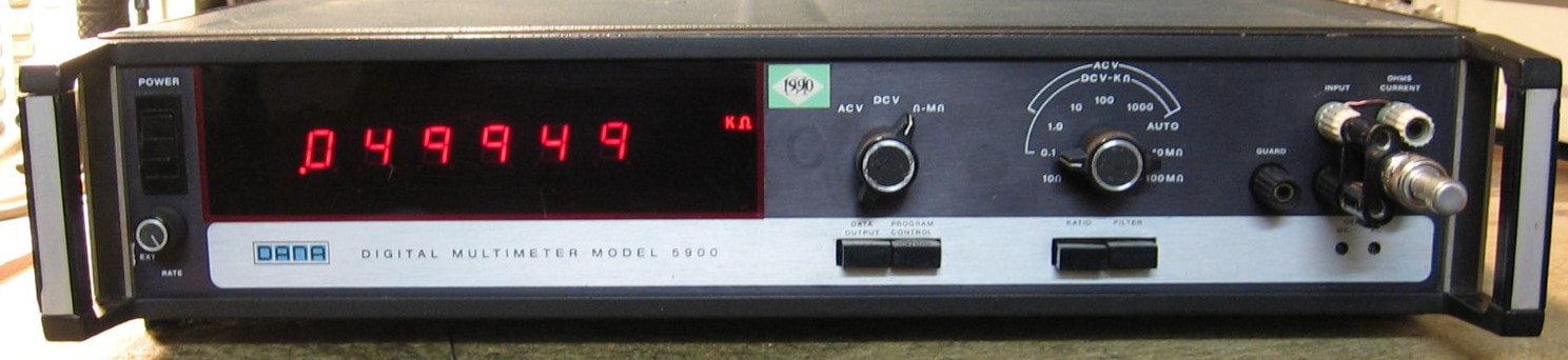
Racal 5900: This is a very mediocre 5-1/2 digit DMM. When it was first working I gave it a grade of C+. After the initial fix, it developed a problem on the digitizer board that I could simply not track down. Moreover, as I was trying, I blew up some of the power supply. After the P/S was fixed, then it developed display problems. Since this was such a poor piece, I decided to relegate it to the "It's Dead, Jim" pile. I still have the Racal 6000 6-1/2 digit DMM, but that is only marginally better. Racal did make some very nice pieces - their DMM's, in my opinion, are universally poor.
Postscript: A few more transistor replacements and the thing started to work again. For how long, who knows. So I removed it from the "It's Dead, Jim" pile and reinstated it as part of the main collection. (PDF) Grade: C+
This piece took about one month to eventually fix. At some point, some of the power supply failed in an overvoltage condition and took out a Zener, electrolytic cap and a pass transistor. There was also some considerable rework necessary on the switching board thanks to the previous repairman. But most of the problems centered on the digitizer board. Conceptually, the digitizer passes the input signal, charges up a capacitor, and then discharges it (and measures the discharge time on the main digital mainboard) by switching in either the +10 or -10 volt reference (depending upon the polarity of the input). I determined that one of the four transistors making up two flip-flops in the polarity detect circuitry was bad. After replacing that, the digitizer often went into oscillation, meaning that there were multiple zero crossings on the discharge and, of course, a bad measurement. The digitizer integrator is an LM301 and it was being run from +20 and -20 volt rails. Which is odd, because almost all of the datasheets for the LM301 specify a maximum of +/-18 volts. And most likely, the -20 volt supply reached -26 volts when the P/S failed. So I replaced the LM301 with the military LM101 version which can take the higher voltage. Everything appeared to function, except the display read about a 0.6 mV offset between a +1 and a -1 volt DC input. No matter which adjustment pots I tried, I couldn't get rid of this offset. Then it occurred to me that I had earlier replaced two JFET switches that feed in the +10 or -10 volt references into the discharge cycle thinking that had something to do with the funky behavior. I should have looked at the parts list because Racal specified a matched set for the two JFETs, not a random set from my junkbox. So I pulled out a bunch of identical JFETs, tied gate to drain and measured the resistance from source to drain until I found a pair that were only off about 2 ohms (300 ohms was the nominal Rds). Put those in and my 0.6 mV offset disappeared. Gee, what a surprise! So the 5900 is now essentially fixed. However, I'm sure there are still some marginal solder joints somewhere because once in a while the leading digit of the display will turn off until you rap the case good and hard. But, enough already.
Postscript: Turned it on, worked for about one minute, then overload on all ranges. I have reworked the digitizer board so many times that it is falling apart. At this point, this piece is what we call "beyond economical repair." After a few days, it has calmed down so it doesn't overload and the readings are approximately right. But there is a lot of random noise on the readings (presumably coming from the digitizer board), so the piece is, for all extensive purposes, unusable. Finally, one day in desperation, I purposefully grounded the gate of the JFET that feeds the input to the digitizer board because I suspected the input was not getting through. The noise abruptly stopped and the piece now functions perfectly. I have no explanation other than I shook the guts of the JFET loose?
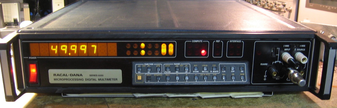
Racal 6002: 6-1/2 digit DMM. My unit has Option 41 (10 mVDC range) and Option 34 (Ratio Board) in addition to the usual DCV, ACV and Ohms functions. Sort of like the Fluke business model, Racal also sold a basic 6000 that one could add options to (the 6002 = 6000 + some pre-installed options). The best 90-day DCV and ohms accuracy is 0.003%, the ACV accuracy is a bit anemic at 0.07%. The mV AC noise floor is also a bit too large in my opinion, although maybe it can be further adjusted. Racal called this a "microprocessing digital multimeter" because it can do some very basic arithmetic (like many other DMMs of that era). All in all, not very impressive. I would put my HP 3455/6, Datron 1062 and Fluke 8502 in the top tier and this Racal 6002, along with the Solartron 7065 and Guildline 9577, in the bottom tier. Every time you turn the unit on, it goes through a pretty long calibration check. I guess that's not too bad, but it also does it every time you change the number of digits to be displayed (4-1/2, 5-1/2, 6-1/2). The manual does give a procedure to turn the auto-cal off, however. Although the build quality is fine, there seems to be an unnecessarily large amount of point-to-point wiring and an even larger amount of big-honking relays. And Racal chose to put a loud fan in this unit (although they did seal up the critical temperature-sensitive boards). (PDF) Grade: B+
This was advertised as "doesn't power up," and the initial inspection showed a blown 3/4-A line fuse. I replaced the fuse and slowly cranked up the AC voltage on the Variac. It was already drawing the 3/4A by the time I got to about 25 VAC. The culprit was a single 10 uF tantalum on the input of one of the three terminal regulators. The nine numeric LED displays were not uniformly bright and I can't have that, so I was lucky to find an eBay seller who had nine of the exact part number for $13. The piece is calibrated by storing software correction factors and that was easy enough to do. However, there are a substantial number of analog adjustments that can be done prior to the software cal and Racal chose to require you to have several specific support boards. Bah, humbug.
Postscript: Turned this on one day and all the DC and ohm readings were extremely noisy. For instance, on DC, the readings fluctuated several mV at low ranges and almost one volt on the higher ranges. A quick look at the dual slope integration waveform showed the noise, which looked like it had a frequency of about 250 kHz. Since there is absolutely nothing in the 6002 that operates at 250 kHz, I was a bit perplexed. But since the noise on the waveform influences the zero crossing detector, which ultimately is used to compute the number shown on the display, it was no surprise what I was seeing. A few days of debug proved nothing. Then I casually tried the AC function only to find that the readings were stuck at about 0.1 volt for all inputs and ranges. Back to the debug for a few more days until I basically gave up. But at least maybe I could fix the AC function? It didn't take long to find a faulty -15 volt regulator on the AC board that was outputting about -1.6 volts. A new regulator was put in and I fired the 6002 back up. Not only were the AC readings now approximately correct, but the display wasn't gyrating. I then switched to DC and ohms and they were also rock solid. What happened is that bad regulator hangs off the -24 volt rail and it put a 250 kHz oscillation on the -24 volt line. Virtually every op amp used in the 6002 runs off of +/-15 volts, except for one notable exception - the integrator which uses +/-24 volts. Hence the noise on the integrator. Moral to the story as mentioned in the Repair section at the end of this web page: always, always check the power supply and use a scope to be sure. My initial DC check of the -24 volt line at the beginning of all of this did not show the AC fluctuation of course.
Postcript^2: One day the 6002 powered up, went through its DC and ohms self-cal as it always does on start-up, then threw errors #31 and #32. Consulting the service manual, these errors are for DC and ohms non-volatile number out of spec. Moreover, the actual 6002 readings were nonsense - e.g., -17 ohms for a 50 ohm resistor. I pulled the non-volatile storage board out which consists of one memory chip, four logic chips, and a bunch of transistors. Luckily, the four logic chips were socketed and were easily tested on my IC tester - they were all good. Then I went poking around with an ohmmeter and found one tantalum capacitor shorted. This cap went from the -30V line through a resistor divider (with the other end at 5V) to one of the logic chips. Replaced the tantalum and the 6002 now works fine.
Postscript^3: And this is why I post repair notes. Turned on the 6002 one day and threw errors #31, #32 and #12. Since the last time, the problem was a tantalum on the non-volatile storage board, I pulled the board out and found yet another shorted tantalum. This time, I replaced them all. I then had to run through the cal procedure. After completing the cal, I assembled all the covers only to find that the unit was not working correctly on ACV. Turns out that the cover of the (removable) module is a piece of phenolic with metal on the underside. One of the AC adjustment caps is a screw and it was out far enough to make contact with this metal underside. Pretty dumb. I don't think it would have touched anything else, but I turned it back down a little (so my cal is slightly off) and it works fine now.
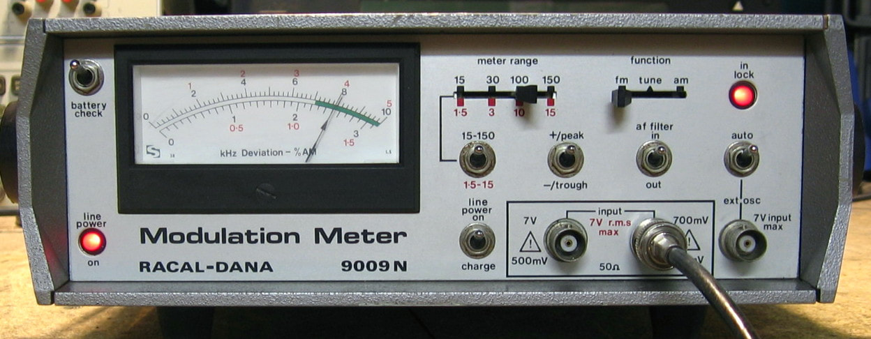
Racal 9009N: Modulation meter, 25 MHz to 1 GHz. The 9009N is a basic, no frills AM and FM modulation meter. Although the unit is spec-ed to 1 GHz, mine easily locked on to signals at 2 GHz. It is quite similar in performance to my Marconi TF-2304. The "N" model differs from the regular 9009 in two ways: 150 kHz maximum FM deviation (vice 100 kHz), and a higher input signal level (50 mV to 7 V vice 10 mV to 1 V). My biggest complaint is the accuracy. Racal specs the basic accuracy as +/-2% of full scale, meaning that if you are on the 100 kHz deviation scale and try to measure a 30 kHz deviation, you can get anywhere from 28 to 32 kHz (which is almost 7% off). On top of this, the linearity of the meter seems not to be very good. But with careful range switching, you can get pretty close to the truth. And the price tag was just right: $20. (PDF) Grade: B
This piece was advertised in condition unknown. Upon receipt, the unit powered up and seemed to work fine, although the readings were a bit low indicating it needed some adjustment. I left it on in my basement and when I came back 30 minutes later, there was the unmistakable stench of burnt electronics. Nothing was emitting smoke and I didn't see any burned parts. The unit is filled with tantalum capacitors and four electrolytic capacitors. I obviously started looking at the tantalums, but I didn't see anything amiss. When I looked carefully at the electrolytics, however, I saw a greenish stain extending out from the bottom of all four about 1/4-inch. Obviously they had leaked decades ago since the stains were completely dry. I removed the four 47uF//16V capacitors and found that they all had excessive ESRs - some as high as 60 ohms. After replacement and a few tweaks of some adjustment pots, the unit seems to be working just fine.
Modulation Meter Bonus Rant: With the 9009N, I now have 8 modulation meters (enough already!). I can roughly rank them from worst to best as follows: 1) Marconi TF-2304, 2) Racal 9009N, 3) E-Jin PJN-0012, 4) Wavetek 4101, 5) Boonton 8210, 6) Boonton 82AD, 7) Marconi 2305, 8) HP 8901A. The first four are strictly analog designs and I have found the Wavetek 4101 to be the most accurate. The last four are digital models with the HP 8901A and Marconi 2305 fairly close and clearly better than the Boonton models. Don't get too hung up over these modulation meter accuracies however; it is often the case that the modulation settings on a signal generator are actually much less accurate. For instance, my HP 8642A signal generator, which retailed for over $40,000, has an FM deviation indicator accuracy of +/-5%.
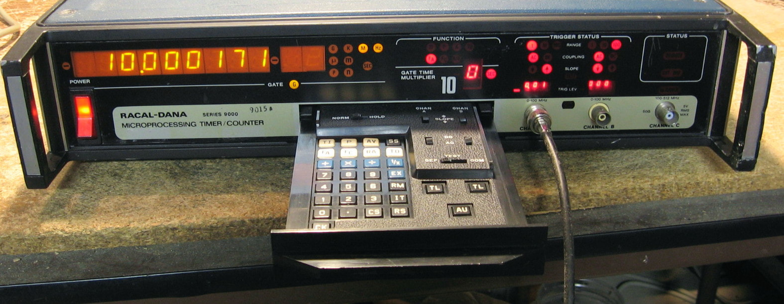
Racal 9015: 100 MHz universal counter. Kind of an odd beast with all controls done via a pull-out keyboard. My basic unit is good to 100 MHz and does the usual frequency, period, time interval, totalize, etc. It looks like it has a TXCO, not an OXCO so I don't know how stable it truly is. Racal called this a microprocessing counter because the keyboard allows you to do some basic arithmetic calculations. For instance, you can toggle between frequency and period by pressing the 1/x key. It does have an unfortunate quirk in that you have to press the autorange key to set the trigger level and sensitivity range every time upon startup. And it really doesn't use the number of available display digits very effectively. All in all, pretty much just a basic counter and my guess is that it wasn't a very good buy back in the 80's compared to the competition. (PDF) Grade: B+
This piece was advertised as working, but one look at the eBay listing photo convinced me that this was a lie. When received, the unit powered up with the External Reference light lit and was totally unresponsive. A check of the -12V rail showed it to be about -3V. Moreover, the 10 MHz internal reference looked like crap. I pulled the 7912 regulator and it tested fine. With the regulator out of circuit, I checked the resistance to ground on the -12V line and it was zero ohms. So whatever initially dragged the -12V line down to -3V finally died in a short. Yes, once again, it's time for everybody's favorite game - find the shorted tantalum! Didn't take long to isolate it to the control board and replace it. Once the P/S was fixed, the External Reference light extinguished (but the 10 MHz reference was a little jittery), but now the Remote light was lit. And the unit , of course, was unresponsive. A rap on the motherboard caused all kinds of havoc, however. Now, all the circuit boards plug into the motherboard using a bunch of pins. Each board has a few larger pins that are used as guide posts. One of these had worked loose on the controller board. I didn't think anything of it, because I still had a couple of guide posts remaining. But it turns out that the guide posts are where the board picks up ground and there are separate grounds on the board. Once the loose post was fixed, I was still back to an unresponsive condition. Looking at the 6502 uP revealed the processor in continuous reset. Turns out that the uP reset is done by charging up a cap (the one that originally had shorted) through a resistor from the 5V line. But the other end of the cap isn't at ground, it is at -12V. So when the cap shorted, it nominally put -12V on the reset line. But I guess Racal anticipated that since they put a protection diode to ground on the line. Fortunately the diode failed shorted and simply held the reset line at ground. Once the diode was replaced, everything worked fine.
Postscript: Another day, another shorted tantalum. Same -12V line as before, but this time the faulty cap was on the I/O board. The initial symptom was that the External Oscillator light was lit, which was surprising since nothing was being fed to the jack. Even after the P/S was fixed, the counter's automatic range functions didn't work (on both channels) and the counter was unresponsive in frequency mode, although the period and totalize functions were fine. Turns out that there is a switch on the rear panel that allows for an external gate and I had inadvertently thrown the switch into the wrong position. Kind of strange that it would render the automatic range function inoperable, but I guess Racal tied that function to the gate.

Racal 9082: HF/VHF/UHF signal generator (British style). Racal made this thing largely for the military supposedly as an HP 8640B clone. Nice try, Racal, but no cigar. The 9082 covers 1.5 to 520 MHz with power levels from 9 to -130 dBm and does the usual AM and FM/PM modulation. The harmonics, spurs and phase noise are OK, but nowhere near as good as the cavity tuned HP 8640B. The real problem comes to light when adjusting the frequency, however. Sure, it has a very convenient channelization setting where you can go up/down in specific increments. But to dial in a specific frequency is a real chore. You first get close in the "fast" setting, then get closer in the "slow" setting, and then put in "hold" and switch on the coarse and fine tune knobs for the final adjustment. Probably takes a good 20 seconds. The frequency display is done by sampling the output and running it through a counter. The counter, however, seems to slow down as you step up through the five bands. So the highest frequency band seems to chug along with display updates about once per second even though the frequency (as seen on a spectrum analyzer) is moving continuously. Quite annoying if that's really how this thing works and there isn't some counter circuitry malfunction I haven't found yet (see postscript below). ($CD) Grade: B
This piece was advertised as condition unknown, but for $47, how could I resist. Upon receipt, the piece powered on but the display was blank (except for the decimal point LED) and there was, of course, no output. A quick check of the -6, 12, and 24 volt power rails showed a short on the 12 volt rail. That was traced to a tantalum on the output board and a tantalum on the front panel optical encoder. Once power was properly restored, the display read 000.000 and would not move under any circumstances. And of course, no output. I checked the main VCO and it was not oscillating. The VCO is varactor tuned and the control voltages were erroneously forward biasing the varactors. I disconnected the VCO and supplied 400 MHz from one of my signal generators. Suddenly, the display read 400.000 and there was output. I connected the main VCO back and this time supplied my own DC voltages to reverse bias the varactors. Again, the thing properly responded. So that pretty much left me with a working unit except for the varactor control. The varactors are tuned from the output of the main PLL and the PLL was not working. The clocks going into the PLL are derived from a decade counter that gets programmed by the logic board. Yet the programming enable was stuck on disable preventing clocks from being generated. Feeding this counter was a simple CD4011 quad nand gate and I spotted one of the gates that was malfunctioning. Popped in a new CD4011 and the unit was totally fixed! Well, almost fixed - the meter refused to read the FM deviation setting. That was traced to a faulty reed relay on the FM loop board (the relay coil measured 38K when it was supposed to be 500 ohms). Finally, the only other problem was a stuck amplitude Vernier pot on the front panel. That took some WD40 and about 50 ft-lbs of torque to finally free up. Racal certainly had their own way of doing things. I found working on this piece extremely frustrating. There is one right way and several wrong ways to disassemble the unit. God forbid you don't figure out the right way before you start (I didn't) since the manual is of no help.
Postscript: There was a problem with the counter - it was stuck on the slowest update rate (1.6 sec gate time on the highest band) because a 7474 latch that decodes the tuning rate switch was defective. Now things operate as a normal signal generator should.
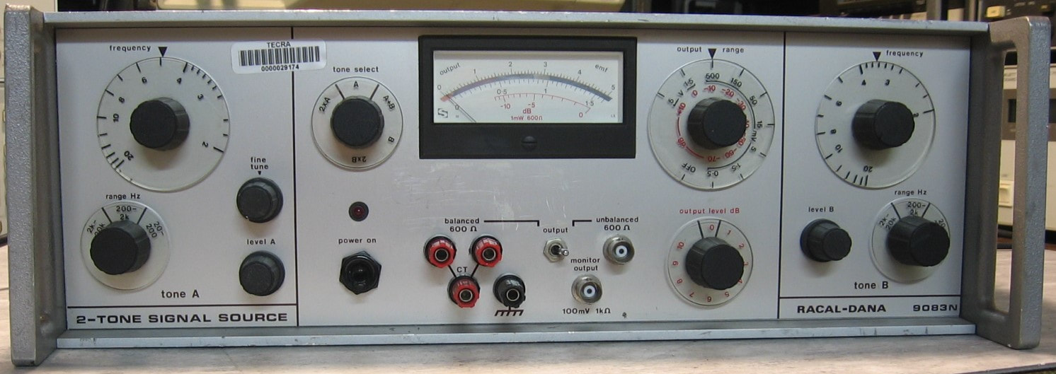
Racal 9083N: Two-tone generator used for intermodulation distortion measurements. The 9083N consists of two identical sinewave generators and some op-amps to deliver either one or both to balanced and unbalanced front panel outputs. There are step attenuators and frequency and amplitude vernier controls. I can find very little information about this piece, except I do know that the 9083, shown in a 1984 Racal catalog, lists the two sinewave generators as going from 0-10 kHz and 0-110 kHz. Presumably, the "N" in the 9083N is a slight variant and both my oscillators go from 0-20 kHz. Both channel's distortion (at 1 kHz) is about -80 dBc. I was somewhat surprised when I took the covers off and peeked inside. The build quality is superb and better than most other Racal pieces I have. Electrolytics with foam pads underneath, op-amps with plastic holders, wiring harnesses appropriately tied and labeled, high quality pots and switches, etc. Perhaps that is because the main circuit board is labeled "KDP Electronic Systems." (--) Grade: A-
There was no information as to condition provided by the seller, but the price was right: $30. When received, everything seemed to be fine except the A-channel frequency vernier pot needed a squirt of cleaner. The B-channel output's phase noise looks slightly better than the A-channel, but the difference is about 90 dB below carrier, so I'm not going to worry about it. There are 16 adjustment pots in the unit, but without a manual, who knows what they do? I tried tweaking them while watching a spectrum analyzer, but didn't see any improvement on the A-channel's output.
There was no information as to condition provided by the seller, but the price was right: $30. When received, everything seemed to be fine except the A-channel frequency vernier pot needed a squirt of cleaner. The B-channel output's phase noise looks slightly better than the A-channel, but the difference is about 90 dB below carrier, so I'm not going to worry about it. There are 16 adjustment pots in the unit, but without a manual, who knows what they do? I tried tweaking them while watching a spectrum analyzer, but didn't see any improvement on the A-channel's output.

Racal 9300: AC RMS voltmeter to 20 MHz. This unit uses the same circuitry as the Racal 5002, namely an analog multiplier, to calculate RMS. Contrast that to the HP 3400A and Fluke 8921A which use thermocouples. And then there is the Ballantine 323 which exploits the nonlinearity of diodes to do their calculations. But they all seemingly do just fine. For instance, against a 0 dBm, 1 MHz sinewave (223 mVrms), the 5002, 8921A, 9300, 3400A and 323 read 221, 224, 222, 224 and 224 mVrms respectively. Against a -60 dBm sinewave (223 uVrms), the 5002, 8921A, 9300, 3400A and 323 read 217, 230, 221, 230 and 222 uVrms respectively. If only the 9300 had auto-ranging... (PDF) Grade: B+
This piece was advertised as working and it basically was when received; it only needed recalibration. It arrived with an auxiliary GPIB remote control box attached to the side. I have no use for that, so I removed it and stripped it for parts. I probably got about $20 worth of parts which covers the $20 I paid for the piece.
Postscript: Quite a few years later I noticed the 9300 was not providing correct readings at ranges of 1 V or greater (lesser ranges were fine). This led me to the front end attenuator which has a bunch of stages switched in and out by reed relays. Suspecting one relay was bad, I started poking around only to have the thing suddenly working properly. But I could reproduce the fault by pressing down on the sealed "Relay A," which is in the 60 dB attenuator. I pulled the relay out and it tested fine on the bench, so back it went. Seems perfectly fine now. I had already tried touching up the solder joints, but perhaps something internal to the relay needed some convincing - who knows?
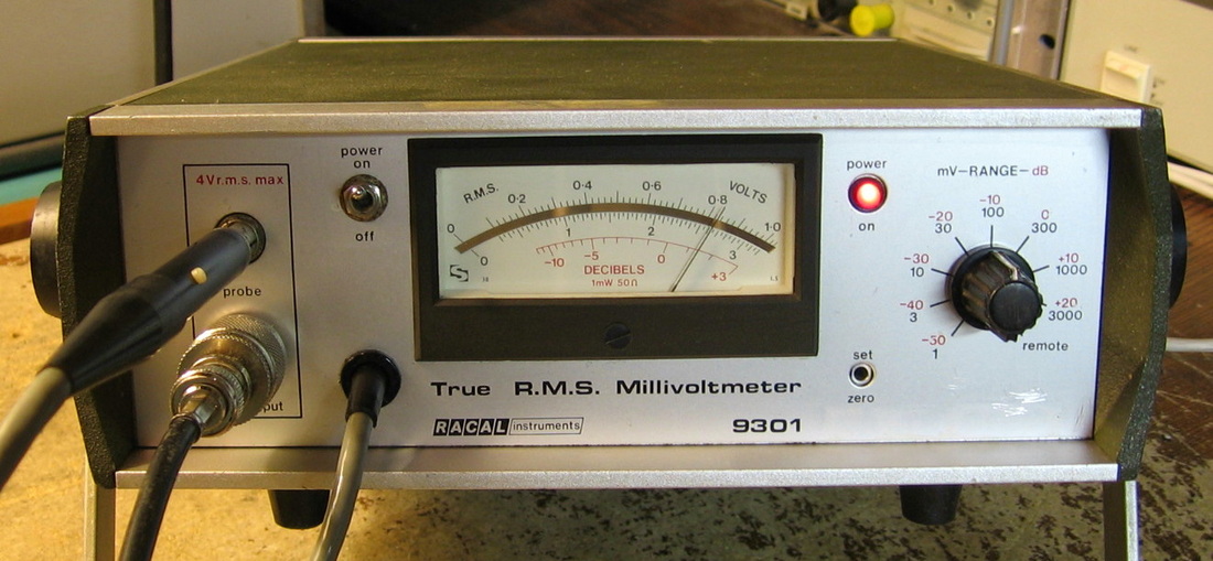
Racal 9301: Broadband RF sampling power meter, 100 uV to 3V rms, 10 kHz to 1.5 GHz. This unit is very much like the HP 3406A in that it uses "randomly" spaced timing pulses to sample the signal (through a probe). HP long ago proved that such a technique yields approximately the correct statistics for the waveform and can thus be used to estimate the power. However, Racal must have looked at the original HP design (10 years later) and decided that although the basic concept and probe design was fine, the detector needed improvement. So as the world moved to thermal RF power measurements, Racal stuck it out with this piece. I guess I would call this innocuous little unit a "sleeper," because it is quite nice and puts the HP 3406A to shame. Unlike the 3406A, which has a tendency to fluctuate a few dB across a relatively small frequency interval, the 9301 pretty much is flat across frequency. The basic accuracy is 3% of full scale + 2% of reading, which is OK, but not great. One can use the probe in a variety of ways, but the best way is to stick it into the jack on the front panel and hook your signal up to the connector below that. The 9301 has a built in 50 ohm termination that gets internally routed to the probe. Racal recommends this procedure unless you absolutely can't do it this way (like probing a circuit board). Also has a few other niceties such as a hold button on the probe and external DC power jacks on the back panel. (PDF) Grade: A-
No description of condition in the eBay listing, so I didn't know what to expect. What I got was a unit that powered on but was completely unresponsive to any input. Naturally, I suspected the probe, but was unable to disassemble it and so I took the covers off the main unit and started to poke around. When I pulled the cover off of the bottom board, I was met with an unbelievable stench. Staring at me were the remnants of a 47 uF tantalum capacitor that burnt and exploded. Goo was all over several square inches of board wafting noxious fumes into my nostrils. After that was cleaned up, I powered up the unit and again it was unresponsive. The bottom board has about 10 tantalums on it. A few go from the 15 or -15 volt rails directly to ground, a few are hung off the supplies after a ~500 ohm resistor and a few are hung off the supplies after either a 5 or 50 ohm resistor. To make a long story short, four tantalums had shorted and blew out two of the resistors to the rails. The four capacitors were replaced temporarily with electrolytics and the resistors were replaced. The unit sprang to life, calibrated perfectly and seems very happy. As a precaution, new tantalums were ordered and all of them were replaced.
No description of condition in the eBay listing, so I didn't know what to expect. What I got was a unit that powered on but was completely unresponsive to any input. Naturally, I suspected the probe, but was unable to disassemble it and so I took the covers off the main unit and started to poke around. When I pulled the cover off of the bottom board, I was met with an unbelievable stench. Staring at me were the remnants of a 47 uF tantalum capacitor that burnt and exploded. Goo was all over several square inches of board wafting noxious fumes into my nostrils. After that was cleaned up, I powered up the unit and again it was unresponsive. The bottom board has about 10 tantalums on it. A few go from the 15 or -15 volt rails directly to ground, a few are hung off the supplies after a ~500 ohm resistor and a few are hung off the supplies after either a 5 or 50 ohm resistor. To make a long story short, four tantalums had shorted and blew out two of the resistors to the rails. The four capacitors were replaced temporarily with electrolytics and the resistors were replaced. The unit sprang to life, calibrated perfectly and seems very happy. As a precaution, new tantalums were ordered and all of them were replaced.

Racal 9303: Broadband RF sampling power meter, -77 to +23 dBm, to 2 GHz. This piece is similar to the Racal 9301 shown above, except it has a microprocessor and digital display. Unlike the 9301, the 9303 has an external sampling head (shown in the picture sitting on top of the unit). The basic accuracy is about the same, about 0.25 dB. The construction is quite nice and it looks like the digital section was largely stolen from the Racal 5002 (or vice versa). Even though it is spec-ed to -77 dBm, I've never been able to get it to read anything below -70 dBm. But that's still a whole lot better than many thermistor RF power meters that only go between +10 and -30 dBm. My guess is that since the sampling head is calibrated from the front panel calibration port, and both full scale and "noise" voltages are supplied, the internal noise of the 9303 is a bit too large to set the noise floor at -77 dBm. It takes about 3 seconds for a reading to stabilize and even longer if digital averaging is selected. The knobology is unique to Racal and selecting things usually requires a brief consult with the operating manual. (PDF) Grade: A-
The unit was being sold with an Error 01 flashing on the display. This means that the RAM has been corrupted usually due to a discharged backup battery. And so it was. The 3V lithium battery was toast and was replaced with two AA alkalines in a sealed holder. I quickly ran the 9303 through its paces with a signal generator set to +10, 0, -10, ..., -60 dBm and everything looked fine. Then, one hour later I tried again and the unit was completely hosed, usually reading Underrange on most inputs. A morning was spent trying to debug the thing, but everything sort of looked to me like it was operating (although it was a little hard to diagnose 300 psec pulses charging a 1.5 pF capacitor). I got nowhere fast even though I was mostly convinced that the sampling head was the problem (I unplugged the head and injected pulses into the socket and the power reading was reasonable). I put the piece away for a day and when I turned it on, it worked fine. I left it on for many hours and went through the adjustment procedure, which also did fine. So it looks as though this piece fixed itself! Perhaps some capacitors reformed?
Postscript: Preemptively replaced the two Rifa 0.0047 uF Y-capacitors hanging off the power switch with non-Rifa 0.0047 uF Y-capacitors.
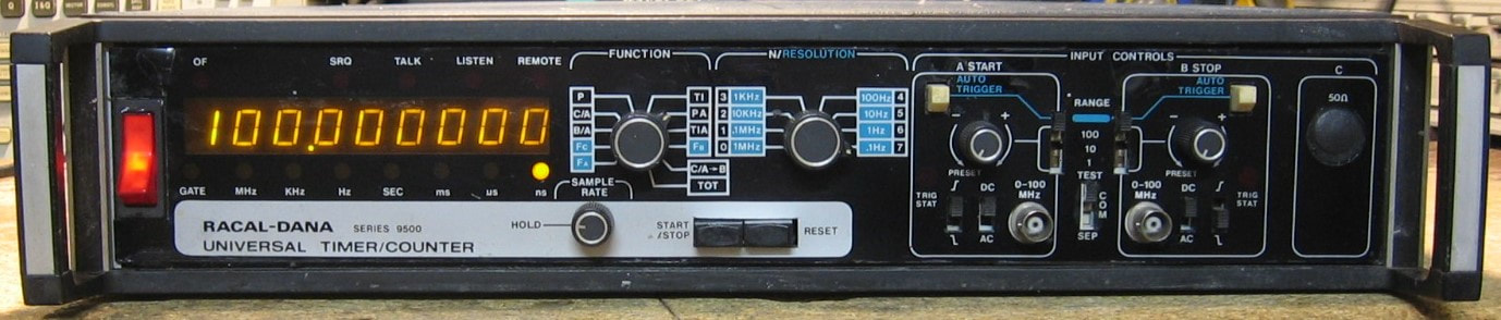
Racal 9515: Basic dual channel 100 MHz 9-digit universal counter. Does the usual stuff and is on the whole a very boring piece. Unfortunately, mine only has the TCXO, not an OCXO. However, it does have Option 01 - rear panel inputs. Sounds like a nice feature, but think again. Because if you want to use the front panel inputs, which is 99% of the time, the cables running to the back panel jacks cause reflections and destroy the ability to count at high frequencies unless terminated in 50 ohms (see the entry for the HP 53132A counter). The counter is rated to 100 MHz and will count up to about 108 MHz. Contrast that to the similar HP 5334A which is rated the same 100 MHz, but will count to 150 MHz. So much for over-design. (PDF) Grade: B
The seller advertised this piece as "smelled smoke when I turned it on, but couldn't locate the source." I didn't smell or see any smoke when I first turned it on but I did notice a burned tantalum capacitor that must have been the original problem. The capacitor surprisingly didn't burn to a short like they usually do, but rather burned to about 30 Kohms, so the 9515 actually worked fine. The capacitor was replaced and the Option 01 cables disconnected. The front panel plastic was separating from the metal chassis and was glued back on.
The seller advertised this piece as "smelled smoke when I turned it on, but couldn't locate the source." I didn't smell or see any smoke when I first turned it on but I did notice a burned tantalum capacitor that must have been the original problem. The capacitor surprisingly didn't burn to a short like they usually do, but rather burned to about 30 Kohms, so the 9515 actually worked fine. The capacitor was replaced and the Option 01 cables disconnected. The front panel plastic was separating from the metal chassis and was glued back on.
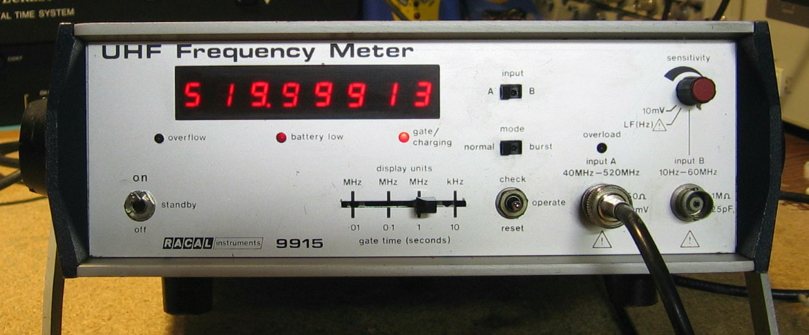
Racal 9915: UHF Frequency Meter, better known as a counter. I don't quite understand Racal's marketing strategy other than to conjecture that they were going after the RF crowd and they thought the word "counter" might be too scary? It has a 50 ohm "A" channel that goes from 40 MHz to 520 MHz (via a prescaler) and a 1 megohm "B" channel that goes from 10 Hz to 60 MHz. Count gate times are selectable at 10s, 1s, 0.1s and 0.01s. And now, here come the quirks! The "A" channel has a PIN diode and reed relay to keep the user from blowing up the front end; the sensitivity of the "A" channel is fixed. On the other hand, the "B" channel has a sensitivity pot and can withstand 250 Vrms (to 10 kHz; de-rated at higher frequencies). There is also the capability to count a burst and the rear panel brings out an internal AGC level (50 dB dynamic range). Options include a battery pack for field use (mine doesn't have) and an OCXO (mine does have). Kind of a bizarre unit, but for $10, how could I resist! (PDF) Grade: B
This piece was advertised as "could not get the unit to display output on screen." But the photo of the back panel showed in big black letters, "This unit is set for 223-251 VAC operation," so what did you expect? Fortunately it just required a few wiring adjustments on the internal terminal strip feeding the mains transformer to set it to 120 VAC. A few spritzes of lube to free up the switches and all is well.
This piece was advertised as "could not get the unit to display output on screen." But the photo of the back panel showed in big black letters, "This unit is set for 223-251 VAC operation," so what did you expect? Fortunately it just required a few wiring adjustments on the internal terminal strip feeding the mains transformer to set it to 120 VAC. A few spritzes of lube to free up the switches and all is well.
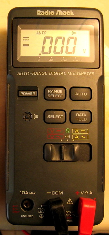
Radio Shack 22-163: Generic 3-3/4 digit multimeter "ideally suited for field, lab, shop and home applications." Basic accuracy specification of +/-0.8% for DCV and +/-1.5% for ACV, DCI, ACI and R, making this about the most inaccurate meter I have (oh wait, see the next entry). About the only thing that's nice is that it runs on two AA batteries (OM) Grade: C

Radio Shack 28-4013: A poor man's version of the Simpson 260. Very poor. Living homeless on the street kind of poor. The box (I still have it) says "easy-to-read mirrored meter with color-coded scales." Unfortunately, the meter is so small, it is anything but easy to read. The major gripe is the test leads which don't match anything else I have. Lucky I still have the originals. I haven't bothered testing the accuracy of this beast - I really don't want to know. However, I have to bump up the grade a bit since it was an "ArcherKit" and I got to build it. (OM) Grade: C+
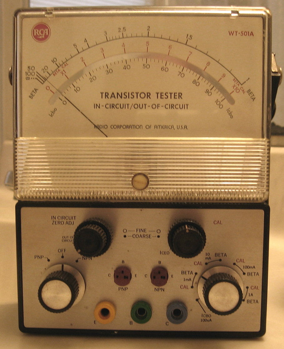
RCA WT-501A: A nostalgic transistor tester to go along with my nostalgic RCA WV-98C VTVM (see next entry). The WT-501A will measure the beta, Iceo and Icbo of bipolar transistors. There is no separate indication of whether a transistor is good or bad - if the meter readings are nonsense, the transistor is toast. Looks like it first sold around 1968 for about $67. Has switchable and adjustable test current settings from about 1 mA to 1 A and will test things in-circuit with a little manipulation of the top two knobs. This piece is much like the Triplett 2590 (see below), but has the advantage that it is battery powered (and a whole lot smaller). In fact, the two D-cells are soldered in because, according to RCA's manual, "battery connections are soldered to prevent current loss due to resistive terminal connections." Really RCA? It's a transistor tester, not the Hubble Space Telescope. (PDF) Grade: B
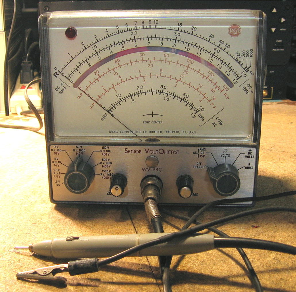
RCA WV-98C: A bit of nostalgia! Known in the trade as the "Senior Voltohmyst," this is a VTVM from the 1960s. The hallmark of such an animal is the 11 Mohm input impedance on all DC ranges, which is quite an improvement over the usual 20K ohms/volt offered by a VOM of that era (e.g., Simpson 260). The RCA VTVM will do DCV to 1500 volts, AC volts (RMS for a sine-wave and peak-to-peak for all others) to 1500 volts with a 3 MHz frequency response on the lower ranges, and resistance to 1,000 Mohms. Of course, you pay for the improved input impedance by having to plug it into AC power. Comes with a probe that has a switch to insert an internal 1 Mohm resistor in DCV mode and an alligator clip for ground. The ohms circuitry is powered by a 1.5V D-cell. The specification is approximately 3% of full-scale. But given that there were probably few electronic items in 1960 that could generate voltages accurate to 3%, I guess you could have gotten by with this piece back then. Construction is adequate with a single PCB to hold the 6AL5 and 12AU7A tubes. And it takes a bit of extra work to zero the ranges (and set infinite resistance in ohms mode). Probably deserved a high grade 50 years ago, but I will simply give it an adequate grade today. (PDF) Grade: B
The seller implied that the piece worked and he was basically correct. But since this piece was 50+ years old, I suspected I would have mechanical problems. And indeed I did! Required were 1) new alligator ground clip, 2) clean the rust/corrosion off of the probe tip, 3) spritz the zero and ohms pots, 4) re-glue the insert to the function switch knob, 5) rework the probe cable connector which developed a non-infinite resistance between the center pin and ground, 6) new knobs for the zero and ohms pots, and general cleaning and calibration. Everything seems to function properly, although it is a bit out of spec on the lowest DCV range (0.5). Probably some of the "precision" resistors have drifted - I'm not going to worry about it.
The seller implied that the piece worked and he was basically correct. But since this piece was 50+ years old, I suspected I would have mechanical problems. And indeed I did! Required were 1) new alligator ground clip, 2) clean the rust/corrosion off of the probe tip, 3) spritz the zero and ohms pots, 4) re-glue the insert to the function switch knob, 5) rework the probe cable connector which developed a non-infinite resistance between the center pin and ground, 6) new knobs for the zero and ohms pots, and general cleaning and calibration. Everything seems to function properly, although it is a bit out of spec on the lowest DCV range (0.5). Probably some of the "precision" resistors have drifted - I'm not going to worry about it.
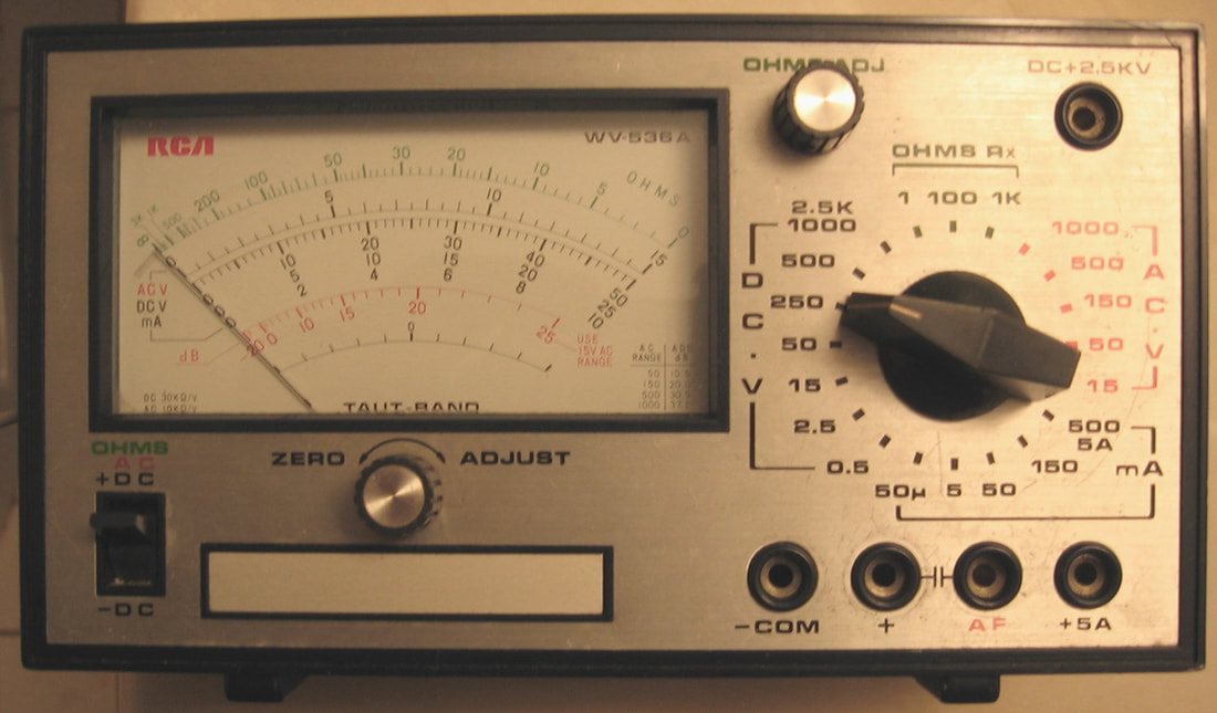
RCA WV-536A: "Shop Special VOM" it says on the back panel label. I have no idea what "Shop Special" means, but this is a basic 30K ohms/volt VOM probably from around 1970 (I'm just guessing). It is labelled "RCA Electronic Components, Harrison, NJ, Made in Japan" on the back. I can find nothing about this on the web and I would consider myself lucky if this thing's accuracy was 5%. But it was only $2.99 and I needed an afternoon of entertainment. (--) Grade: B-
The seller advertised this piece as needing work. The pictures showed some loose wires, battery corrosion, a burnt out resistor removed from the board and taped to the front panel, and two black "X" marks on the board. I managed to clean up the corrosion and took a guess where the broken wires went. Everything seemed to work except the ohms function. There is a fuse inside which consists of a piece of thin wire between two posts. The wire was gone so I tacked in a piece of ordinary hookup wire for the time being. That left the missing resistor which experimentally I found to be 24 ohms. So my guess is that a previous owner put high voltage across the inputs while it was in ohms mode and fried both the fuse and the resistor (perhaps he replaced his fuse with a piece of thick wire like I did?). So now everything works. My only complaint is the meter movement which suffers excessively from orientation. Lay the unit flat on the bench and the readings are good. Place it in a vertical orientation and it reads about 10% low. Most analog meters suffer from this orientation problem, but this meter is the worst I've seen. Oh well, it's not like this thing is going to replace my 7-1/2 digit DMMs.
Postscript: My 24 ohm guess at the missing resistor was a bit off on the ohms x1 scale so I replaced it with a 200 ohm 10-turn pot and adjusted it until the meter was spot on. I also wired in a fuse holder and put a 500 mA fuse in.
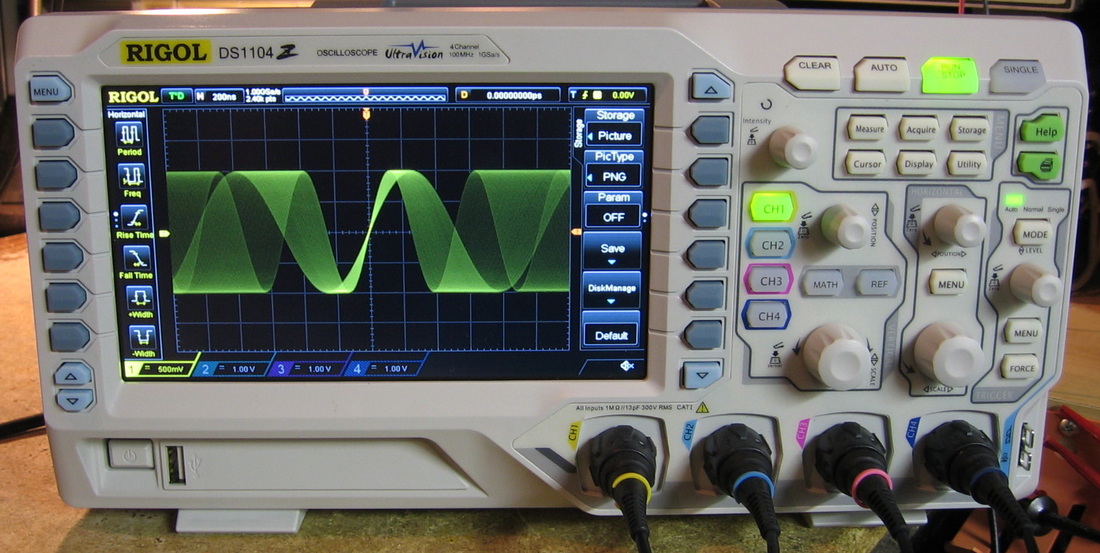
Rigol DS1104Z: Brand new 100 MHz 4-channel oscilloscope from the Chinese. Despite the fact that I have at least 10 other oscilloscopes, I decided to treat myself to one that wasn't more than 20 years old. And it didn't hurt that my insurance company decided that they had been overcharging me for decades and out of the blue sent me a refund check for $3,100. The DS1104Z set me back $780 and you do get quite a bit for that amount. Unlike most older digital scopes, this one has a decent waveform update rate - as much as 50,000 waveforms/sec. Contrast that to the rather putrid 30-100 on some of the 1980-1990 scopes. Plus the scope has a 1 GHz sampling rate and 24 Mpoints of memory, an extensive set of automatic measurements, dozens of trigger types, math functions (e.g. FFT) and a waveform record/playback function. I won't bore you with the specs (which can be found on Rigol's site), but the combination of high update and gradient intensity (see an example of the gradient intensity in the photo) and very bright, crisp LCD make for a pleasing display. While rated to 100 MHz, the 3 dB bandwidth is more like 200 MHz and the scope will easily trigger up to 450 MHz or so (obviously with reduced amplitude). There are a few quirks in the software, typical of the Chinese, but on the whole, the button-ology is adequate. There have also been reported quirks in the firmware involving jitter on delayed waveforms (my unit doesn't exhibit this) and jitter on AC-coupled triggers (my unit does exhibit this). (OM) Grade: A-
Postscript: Rigol released a firmware upgrade to address the delayed-jitter and AC-coupling problems. At least on my unit, the new firmware appears to correct any problems. There is still considerable discussion as to whether or not Rigol correctly implemented in hardware the phase-locked-loop that controls the A/D sampling. I personally haven't come across any artifacts of that, but one has to suspect that the Chinese engineers are in no way as good as, say, their USA Agilent or Tektronix counterparts. So I guess it all boils down to "you get what you pay for."
Postscript: Rigol released a firmware upgrade to address the delayed-jitter and AC-coupling problems. At least on my unit, the new firmware appears to correct any problems. There is still considerable discussion as to whether or not Rigol correctly implemented in hardware the phase-locked-loop that controls the A/D sampling. I personally haven't come across any artifacts of that, but one has to suspect that the Chinese engineers are in no way as good as, say, their USA Agilent or Tektronix counterparts. So I guess it all boils down to "you get what you pay for."

Rigol DSA815-TG: Brand new 1.5 GHz spectrum analyzer from the Chinese (with an assist from Agilent). It is pretty amazing that you can now get a full featured spectrum analyzer with tracking generator for $1,495. Hell, Agilent charges more than that for a cheapie function generator. Weighs about 9 lbs and has a fold-out handle for easy transport. Complete with USB/LAN/GPIB connectivity. Now, other than the upper frequency limit, what drives up the cost of a spectrum analyzer is the phase noise spec and the Displayed Average Noise Level (DANL) spec. The Rigol is spec-ed for phase noise of -80 dBc//Hz at 10 kHz and a DANL of -135 dBm (100 Hz RBW). I've measured mine at -88 dBc and -138 dBm respectively. Your better Agilent scopes achieve a phase noise < -100 dBc//Hz at 10 kHz. I have made DANL measurements on a Rohde & Schwarz FSH3 and an Agilent E4402B at my workplace. This web page's chief technical advisor and proofreader has made measurements on his E4401B. The numbers were -120 dBm, -142 dBm and -148 dBm (all corrected for a common 100 Hz RBW) for the FSH3, E4402B and E4401B respectively. So the Rigol is much better than the FSH3, but not as good as the E4402B or E4401B. However, look at cost. The FSH3 was $6K many years ago when I bought it and doesn't include the TG. The E440X series will set you back at least $15K depending upon options. So I think Rigol did a pretty good job at $1.5K. The menu system is very much like the E440X analyzers. It has a nice "auto" button that will find any single input signal automatically and configure the analyzer for a nice display with the signal at the center and properly adjusted in amplitude, bandwidth, etc. (OM) Grade: A
If I needed to fix this, I would have already put a loaded pistol in my mouth and pulled the trigger. At least there is a 3 year warranty.
Postscript: I managed to get a firmware upgrade out of Rigol and installed version 1.07 over my 1.05. Now the screen properly displays "Input Attenuation" instead of "Input Attention." Gotta love the Chinese.
Postscript2: Someone posted the version 1.08 firmware to eevblog. I posted it to the DSA815. Evidently it fixed some more spelling mistakes.
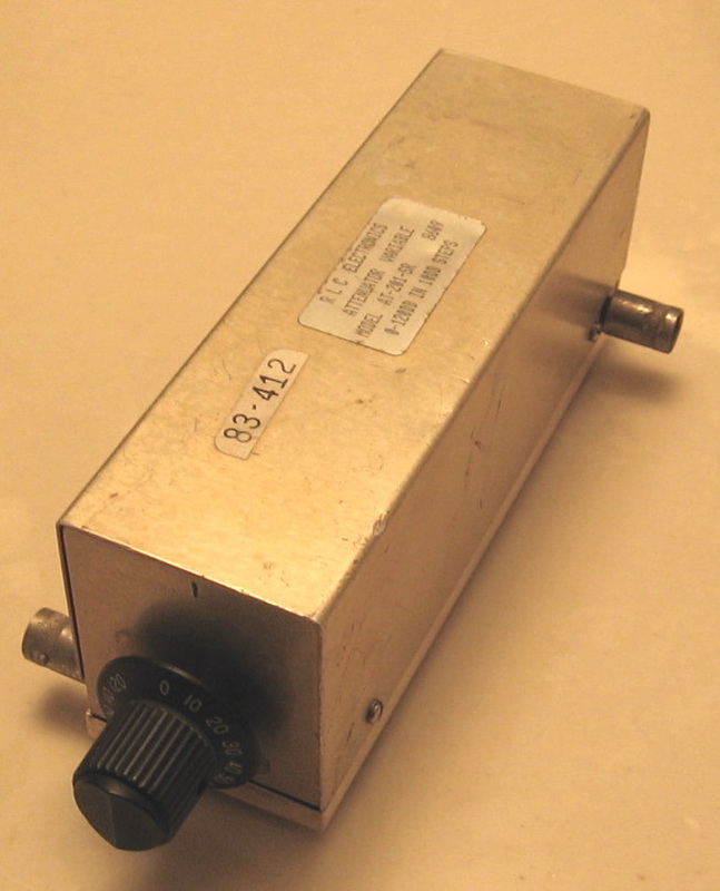
RLC AT-201-SR: Step attenuator, 0 to 120 dB in 10 dB steps. Step attenuators are like BNC cables - you can never have enough and they always seem to wear out eventually. I can't find anything specific to this model in the literature, although RLC seems to still be in business. This one acts as though it is 50 ohms and is relatively flat from 0 to 1.5 GHz (as measured on the Rigol DSA-815 spectrum analyzer). The measured accuracy is < 1 dB, and the switching doesn't exhibit any noise from undue wear. Needed a bit of cosmetic cleanup, but all in all, it was a good buy at $19. (---) Grade: A
Postscript: Now that I have some microwave capability (e.g., Gigatronics 900 sig gen and Tek 2754P spec analyzer, I determined that this attenuator is good from DC to 4 GHz.
Postscript: Now that I have some microwave capability (e.g., Gigatronics 900 sig gen and Tek 2754P spec analyzer, I determined that this attenuator is good from DC to 4 GHz.

Rotek 320: This is a multi-function calibrator for DCV, ACV, DCI, ACI and ohms. It was built in the 1970's and was intended to calibrate 3, 4 and 4-1/2 digit DMMs of that era. The best case accuracy is about 0.006% for DCV, 0.055% for ACV, 0.022% for DCI, 0.055% for ACI and 0.05% for ohms. It also has a vernier control with digital readout of percentage error. Certainly it is not as accurate as the Fluke 343A (DCV) or the Fluke 5200A (ACV) or the Biddle resistance box (ohms), but it is nice to have everything in one box. And it is the only accurate current source I have (other than a precision voltage and resistor). The unit is very large, heavy and well-built. (OM) Grade: A-
The seller advertised this piece as working, except a few ranges are off value. And that's exactly how I found it upon receipt. Moreover, some of the higher ACV ranges were not only off, but fluctuated excessively. Remember, always look for mechanical failures first. In this case, always look for mechanical failures first, second, third, ...., twenty-first. Indeed, there are 21 relays (mostly 4PDT) in this unit and all the signals go through most of them all of the time. I pulled out one relay and measured one of the contacts at about 200 ohms. So my methodology was to measure all the contacts and then apply 400 ma across any with a resistance greater than 0.2 ohms until I burned the crud off and the resistance fell to 0.2 ohms. Well, wasn't that exciting to do that on 21 relays? Sure thing. Anyway, all seems perfectly normal now. There are a couple of random voltages that are slightly out of spec, but then again the HP 3456A DMM that I'm using with this doesn't have sufficient accuracy to determine if I'm out of spec on those ranges.
Postscript: Well, it looks like my current burning technique didn't last long. About one day to be exact. Nor did a dip in Tarn-X. Nor did a soak in alcohol. The only long term solution was to replace all 21 relays. The replacement relays are about $20 a pop, so that was out of the question. However, I did find a seller on eBay and bought 33 3PDT relays for $20. That's my kind of price. Of course, the new relay pinouts didn't match the old relay sockets. But luckily, all but two of the 4PDT relays in the calibrator use fewer than 4 poles. I desoldered all the relay sockets and hard wired in the new relays using two 3PDTs to pick up the 4th pole where necessary. The entire transfusion took about 20 hours and the Rotek 320 is as good as new. Well, a lot of it is new!
S : Sadelco, Sencore, Simpson, Singer, Solartron, Soltec, Systron Donner
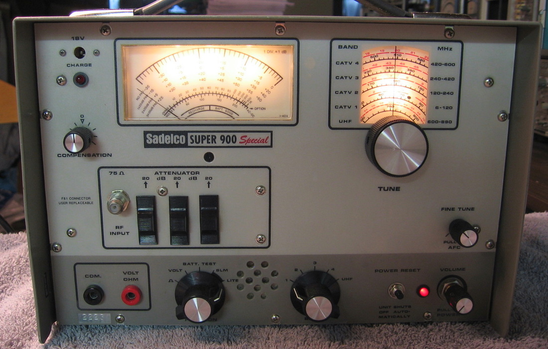
Sadelco 900: A TV/CATV receiver and level meter. Why this is "Super" and why it is "Special" is beyond me. I put an AC power supply inside just for fun. And there are how many over the air TV broadcasts now? (---) Grade: D+
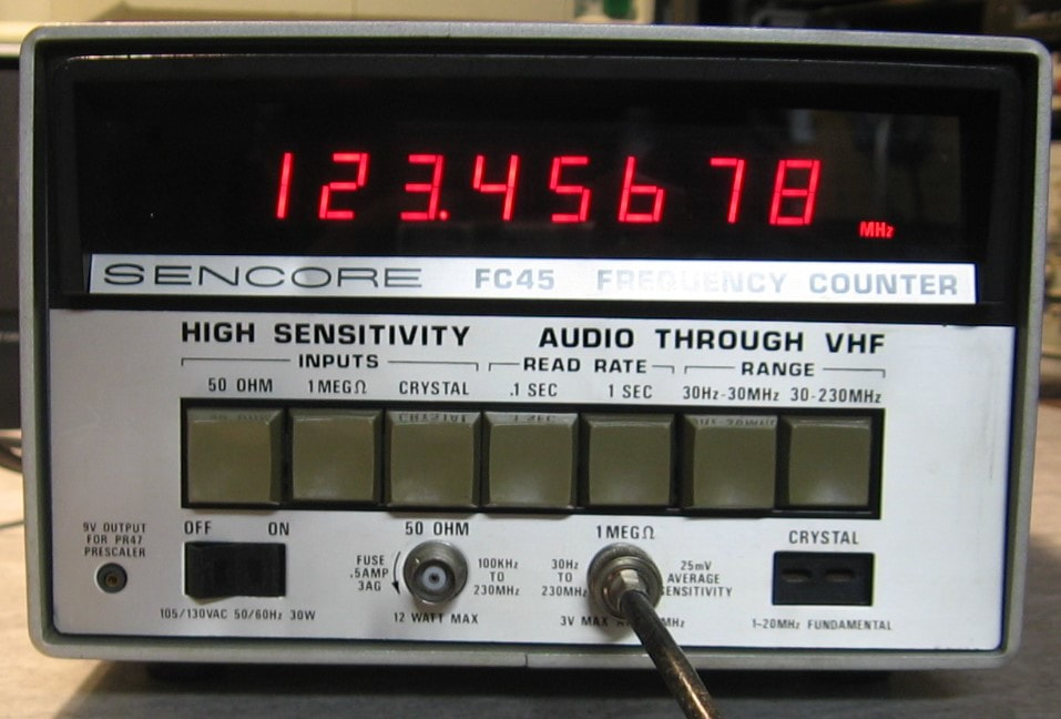
Sencore FC45: 230 MHz counter. The FC45 is a basic counter with prescaler to 230 MHz. It has only 0.1 and 1.0 second gate times and 50 ohm and 1 Megohm input jacks. It is unique among my counters, however, because behind the front panel 50 ohm input jack lies a 12 watt dummy load. Presumably the FC45, built in the late 1970's, was used by CB radio repair technicians who could simply feed the nominal 5 watt transceiver output directly into the FC45. It also has a jack for measuring crystals, another thing repairmen might do back then. The counter contains an ovenized oscillator which is simply a crystal oscillator wrapped in a two-piece Styrofoam shell (held together by rubber bands!) containing two power resistors that serve as the heating element and two diodes that serve as the temperature sensor (which gets fed back to an opamp controlling the voltage to the resistors). Typical of Sencore test equipment back then, the build quality is somewhat cheap and the electrical design a bit awkward in places. (PDF) Grade: B+
Advertised as non-operational, I plunked my $25 down and looked forward to an afternoon or two of entertainment. I wasn't disappointed and upon turn-on, the display was blank. The P/S is a bit convoluted and contains 15, 9, 8.2 and 5 volt elements. Pretty much all of them were wrong. The fault was traced to a malfunctioning diode in the four-diode bridge rectifier circuit of the 9V supply. These are 3A diodes and I didn't have any in my junkbox, but I did have a nice 4A encapsulated 4-terminal bridge rectifier, so that quickly cured the problem. Everything then operated correctly and when I did a final voltage check, one of my DMM probes slipped, I saw a spark, and the unit was then DOA again. D'oh, I hate it when that happens. It only took me a few minutes to find the culprit, a shorted 8.2V Zener that I must have forward biased excessively when the DMM probe touched something nearby. The Zener was replaced and all was well until I decided that the two 10V incandescent lamps (for the Hz and MHz indication) on the front panel deserved to be replaced with LEDs as long as I had everything all apart. But after the replacement, I noticed that when the Hz LED was turned on, the MHz LED also turned on (slightly dimmer). I should have looked at the schematic, because Sencore used two transistors to drive the two lamps. One comes off the Q-output of a 74LS74 latch, but the other transistor turns on by supplying voltage through the other bulb in such a way as the desired bulb lights but the supplying bulb doesn't. This obviously doesn't work correctly with the 2V drop across the LED replacements. What they should have done is use the Q-bar-output of the same 74LS74 to feed the second transistor. Looking at the schematic, I noticed that the Q-bar-output was not used for anything, so I disconnected that second transistor from the lamp circuit and ran a wire from the base of the transistor through a 1.8K resistor to the Q-bar-output. Works great now and I really don't understand why Sencore didn't do it that way in the first place. I also replaced the four electrolytic capacitors in the P/S because why not?
Advertised as non-operational, I plunked my $25 down and looked forward to an afternoon or two of entertainment. I wasn't disappointed and upon turn-on, the display was blank. The P/S is a bit convoluted and contains 15, 9, 8.2 and 5 volt elements. Pretty much all of them were wrong. The fault was traced to a malfunctioning diode in the four-diode bridge rectifier circuit of the 9V supply. These are 3A diodes and I didn't have any in my junkbox, but I did have a nice 4A encapsulated 4-terminal bridge rectifier, so that quickly cured the problem. Everything then operated correctly and when I did a final voltage check, one of my DMM probes slipped, I saw a spark, and the unit was then DOA again. D'oh, I hate it when that happens. It only took me a few minutes to find the culprit, a shorted 8.2V Zener that I must have forward biased excessively when the DMM probe touched something nearby. The Zener was replaced and all was well until I decided that the two 10V incandescent lamps (for the Hz and MHz indication) on the front panel deserved to be replaced with LEDs as long as I had everything all apart. But after the replacement, I noticed that when the Hz LED was turned on, the MHz LED also turned on (slightly dimmer). I should have looked at the schematic, because Sencore used two transistors to drive the two lamps. One comes off the Q-output of a 74LS74 latch, but the other transistor turns on by supplying voltage through the other bulb in such a way as the desired bulb lights but the supplying bulb doesn't. This obviously doesn't work correctly with the 2V drop across the LED replacements. What they should have done is use the Q-bar-output of the same 74LS74 to feed the second transistor. Looking at the schematic, I noticed that the Q-bar-output was not used for anything, so I disconnected that second transistor from the lamp circuit and ran a wire from the base of the transistor through a 1.8K resistor to the Q-bar-output. Works great now and I really don't understand why Sencore didn't do it that way in the first place. I also replaced the four electrolytic capacitors in the P/S because why not?
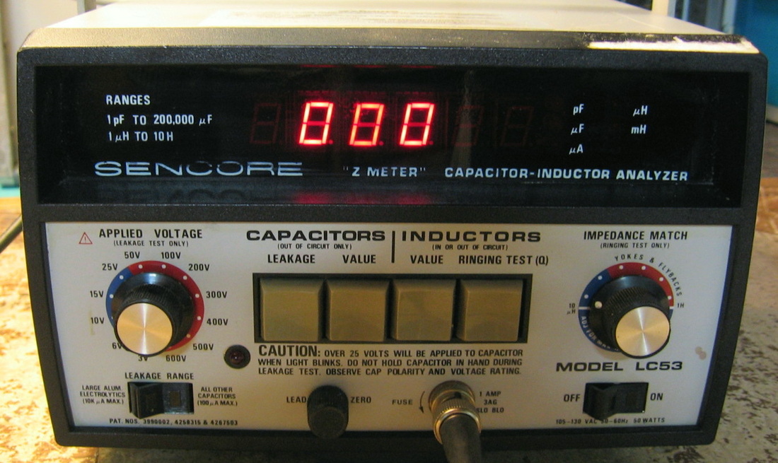
Sencore LC53: Inductance and capacitance meter circa 1980. Measures L with +/-2% accuracy from 1 uH to 9,990 mH and C with +/-1% accuracy from 1 pF to 199,900 uF. Auto-ranges with a basic 3-1/2 digit LCD display, expanding to 5-1/2 digits with the last two digits fixed at 00. This is how Sencore got by with two displayed C ranges, pF and uF. For instance, a 47nF will read 47000 pF. Caps less than 0.089 uF read as pF and greater or equal than 0.09 uF read as uF. Similar deal for inductors. This meter will measure C, L, C-leakage at voltages up to 600 WVDC and inductor ringing. The latter two measurements are not usually seen on LCR meters. Capacitance is measured by charging the component through a known resistor and measuring the time constant. Inductance is measured basically by linearly ramping up a current source and measuring the voltage across the component (V = L dI/dt). More modern meters use an AC signal and measure the complex impedance. Nonetheless, the meter is extremely fast and seems quite accurate. (PDF) Grade: A-
Advertised by the seller as having been used for many years, then suddenly no response to any input. When I opened it up, there was a QA sticker on the frame that said "This unit was built 100% right," signed by some Sencore technician. Well then, it ought to work, no? The seller's description was perfectly correct - pretty much unresponsive to anything. All the P/S voltages checked out, so I started to delve into the schematics. There should have been a sticker on the schematic that said "This schematic was drawn 100% wrong." If you want to see how NOT to draw a schematic, check it out. About 100 little boxes with numbers in them indicating a connection point to another numbered box somewhere else on the schematics. No rhyme or reason to the numbers and no rhyme or reason to the parts numbering. So if the output of a logic gate goes into a numbered box, you have to spend 10 minutes pouring through the schematics to find the corresponding number, then you have to spend another 10 minutes looking at the parts layout to find the component. Sheer torture. After spending about an hour and tracing maybe one logic gate and two transistors, I concluded it would take me the rest of my life to diagnose the malfunction. Oh yes, the schematics aren't drawn in HP style with some sort of left-to-right signal flow, nor are there any circuit theory discussions in the manual. However, poking around I did see one CMOS chip whose output levels seemed suspicious. There was also one IC that had been replaced (the repairman had put in a socket for the new IC). My decision was to replace the 28 chips on the digital board as I was pretty sure the analog board and display board were functioning. I ripped out all the soldered ICs and also discovered, when I decided to remove the previous replaced chip's socket, that the repairman had lifted a few pads on the bottom of the board. He then relied upon a physical connection on the top side of the board between the pad and the socket pin. Not very good with no solder; the ground of the IC was definitely not making contact (I didn't check some of the other pins, but who cares at that point). Bottom line: with new (socketed) chips and proper soldering, the unit is fixed. I guess we will never know whether the two bad ICs were the only culprits.
Postscript: This may be the only piece of test equipment I own that doesn't have a line fuse. Sencore relies upon a thermal cutout in the main transformer. No soup for you! Now the piece has a 1/4-amp fuse in a holder mounted on the rear panel.
Postscript^2: In what has to be the stupidest thing I've ever done, I recently plugged the Sencore into the power strip and it blew the lab circuit breaker. Funny, it didn't do that when I had it plugged in to the isolation transformer. Well, the AC hot comes in to lug 2 of a terminal strip, lug 2 goes to the front panel power switch, returns to lug 3 and lug 3 goes to the primary of the AC transformer. When I put in my fuse, I moved the AC hot to the unused lug 1 of the terminal strip, ran lug 1 to the fuse and back to lug 2. Turns out, lug 1 of the terminal strip was the one connected to the terminal strip's mounting screw into the chassis. So I caused a hot-earth short by my stupidity. After I corrected the problem, the LC53 was not working correctly for inductor measurements. Traced the problem to dirty/frozen pots and all is back to normal.
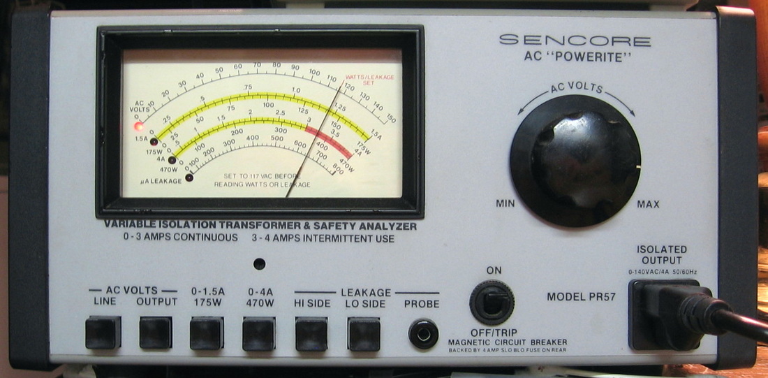
Sencore PR57: Very nice isolation transformer and meter. Good to 4A. Note the LEDs in the face of the meter? Haven't seen that before. Actually came with the leakage probe and the original instruction card. All my equipment under repair goes through this device. I mean I don't want to electrocute myself just yet. (PDF) Grade: A
After several years of heavy use, the paddle on the front panel on/off switch cracked off. This is a combination switch and 4A circuit breaker which is no longer readily available. So I mounted a vanilla switch on the front panel and a separate resettable 4A circuit breaker through the back panel.
Postscript: There seems to be some disagreement as to whether an isolation transformer should propagate earth ground from primary to secondary. The PR57 does propagate the ground, so I decided to replace the outlet with an isolated one and mount a switch on the side panel to cut the secondary ground when desired.
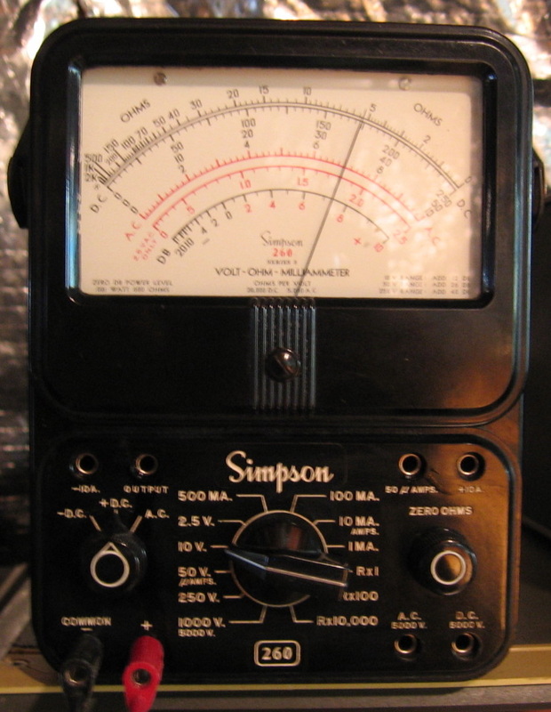
Simpson 260: Series 5 VOM with about 2-3% accuracy. Nice and portable. Thanks, Dan. Everyone bitched and bitched at me because I didn't have one of these. Bitch no more. (PDF) Grade: B+
The battery terminals had corroded badly and the glass was loose. Par for the course with the 260s.
Postscript: The 260 developed a fault where the 100K ohm scale would peg the meter with shorted leads and could not be correctly adjusted to zero with the potentiometer. When I opened up the unit, I saw a lot of corrosion and junk on the main board which I never cleaned off years ago when I first got it. Some de-greaser and a toothbrush seems to have restored things back to normal.
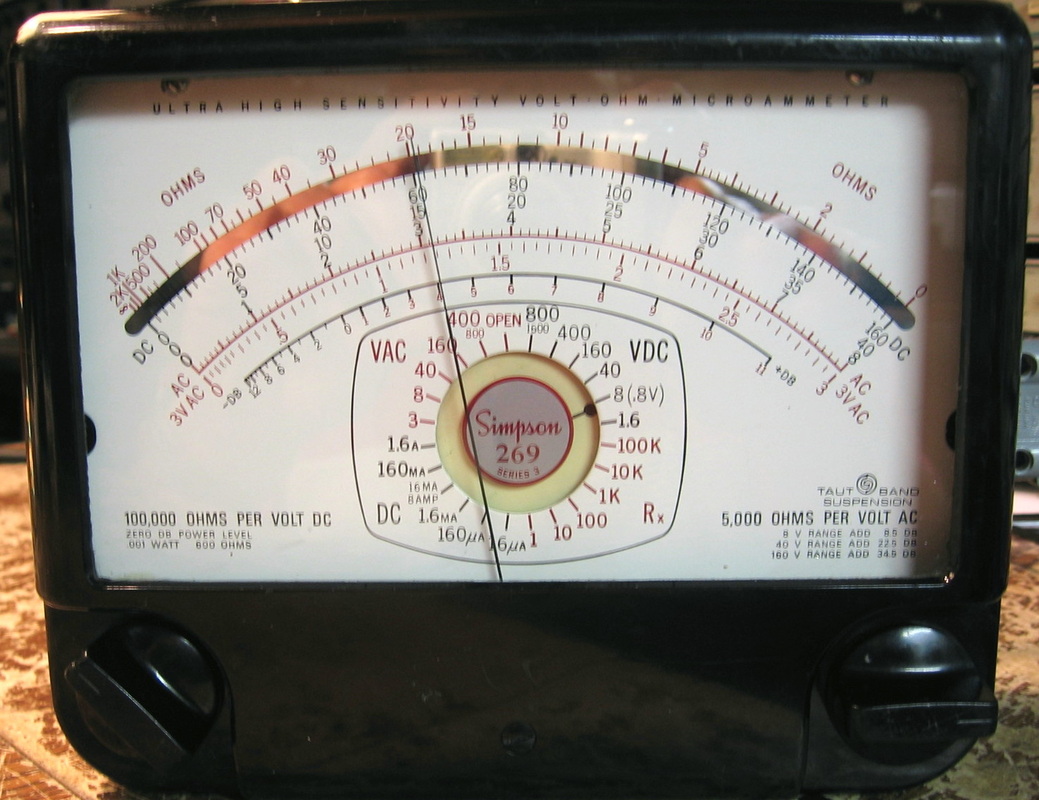
Simpson 269: 7" meter VOM shown here measuring 3.04VDC against 3VDC input. That's 1/2% of full scale (8V) allowable error and is within spec comfortably. The meter takes a long time to arrive at its final destination. This was the second try - the first one I bought had a dead meter. (PDF) Grade: B
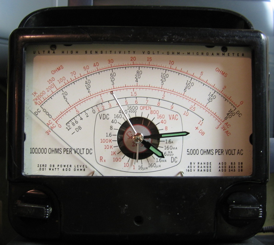
Simpson 269 Surprise!: Remember the first Simpson 269 I bought, the one with the dead meter? Surprise! (---) Grade: A+

Simpson 420: 1 MHz analog function generator. Does sine, triangle and square. That's about it, but hey, what do you want for $9.95? Probably designed for the audiophile given its 600 ohm output impedance. Simpson is synonymous with the 260 VOM which goes back to WWII. I don't associate Simpson with miscellaneous test equipment, but they still are building a few specialty pieces/accessories. According to their web page, the company can trace its origins back to 1927. In 1985, they were purchased by a local Indian tribe in Wisconsin! I can find out very little about the 420 function generator. A schematic is available on the web, but it doesn't quite match the 1987-built version I have. And that's particularly annoying because there about a dozen adjustment pots begging to be turned and it is not entirely clear from the schematic what they all do (I have most of them figured out by watching the output on a scope). Rumor has it that Simpson built the 420 for Wavetek who rebadged it. I would have guessed it was the other way around. But I must say, the build quality is very good and far beyond what I would have expected (from either Simpson or Wavetek). I don't know all the specs, but it looks like the distortion spec (sine wave) is probably 1%. When received, it was about 4%, but I managed to tweak the pots down to about 0.5%. Other than that, it just needed some cleaner sprayed into the pots. (---) Grade: B+
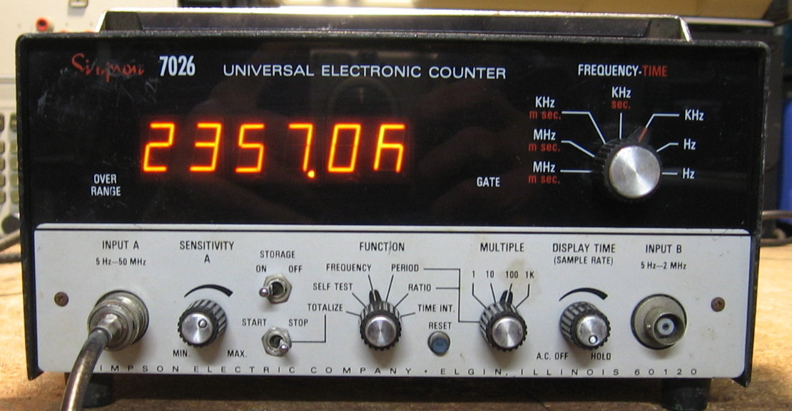
Simpson 7026: Frequency counter to 50 MHz. This is a pretty atrocious counter that does frequency, period, totalize, ratio and interval. It has AC coupled inputs with a basic sensitivity of 50 mV. Mine has the TXCO option which supposedly is good to 1 ppm per year, but I highly doubt that. Build quality is OK; about as cheap as Old Man Simpson (or his ghost) would probably have allowed back around 1970. This is as basic a counter as it comes, and with only six digits, is just marginally better than simply guessing the frequency! (PDF) Grade: C
Advertised as for parts or repair, I was expecting the Panaplex neon display to probably be toast. Surprisingly, only the bottom horizontal segment of the last digit is missing. Unless I can find a cheap replacement, it will have to stay this way. Ultimately, if enough of the digits start to be problematic, I guess I could replace the entire display with 7-segment decoders and LED alphanumerics. When I received the 7026, the fuse holder was missing the cover. When I took of the bottom cover to replace the holder, I saw that someone had soldered a two-wire line cord and plug directly to the pins of the 3-prong AC receptacle on the back panel. That receptacle is the "old" style and the previous owner probably didn't have one. But he then took his line cord, coiled it up, and threw it back inside the piece. He would have had to take all of the covers off in order to use the piece. Very strange indeed. Obviously, I removed the cord since I do have the "old" style AC cord.
Postscript: The very next day, the last digit was now missing several segments. I pulled out the display and wired 150 VDC through a 1 M resistor and all the segments lit up correctly. So my conclusion is that the problem is the 8884A display driver IC. The only one I currently see for sale costs $35, which is more than I spent for the entire counter. Maybe some day...
Postscript^2: I figured I could emulate the 8884A display driver IC with junkbox parts, namely a 74LS48 BCD-to-7-segment decoder, seven high voltage NPN transistors and seven 180K resistors. Luckily, this last digit doesn't require an 8th line for the decimal point (which is unused). I assembled everything on a small perfboard and wired it up to the display board (after I pulled out the bad 8848A chip). All of the digits now work perfectly.
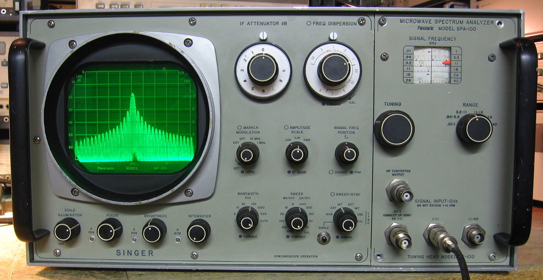
Singer SPA-100: "40 GHz Spectrum Analyzer." I put the description in quotes because it really isn't a spectrum analyzer and really doesn't do 40 GHz as shown. And to make matters worse, it sometimes goes by Singer, Panoramic, or a variety of sub-companies of Singer Instrumentation. As the picture shows, the SPA-100 consists of an MF-100 mainframe and an RF-100 tuning head. Presumably, other tuning heads were available 50 years ago when this beast was manufactured. It will do 11 GHz as pictured; to get higher than that, one needs an external mixer. This threw me for quite a loop when I wasted an afternoon trying to debug why I couldn't see anything when I hooked up a 12 GHz signal to the 11-40 GHz input! Now, follow me on this: A modern spectrum analyzer tunes the 1st LO (usually a YIG) very quickly and thus can put up a full-band span. The SPA-100 uses a microwave triode tube and a mechanically tuned cavity as the 1st LO. So it will only tune as fast as you can turn the front panel tuning knob. The way they get a sweep on the CRT is by sweeping the 2nd LO, not the 1st LO. And that restricts you to a maximum span of 100 MHz centered about where you manually set the center frequency. So it really acts like a receiver with a panadapter on the IF, i.e., a "panoramic receiver." I won't bore you with the specs; they are pretty atrocious by today's standards. And forget trying to do any kind of absolute measurements. The chief utility of this piece is to verify the proper relative spectra of various modulated microwave signals, that's about it. The pictures shows the spectrum of a 7.2 GHz pulse modulated signal out of my Gigatronics 900. Probably a miracle back in the 1960's, but a real boat-anchor today. Grade: B- (OM)
Advertised as working, I fully expected the seller to be joking, but he wasn't - it did work. It did need some tuner cleaner and the HV wire to the CRT was loose. Other than that, the only thing that didn't work right was the 1 MHz RBW filter. But when I took that circuit out of the unit and tested it on the bench, I couldn't find anything wrong with it. So back it went and it now works fine in the unit. Probably just a bad connection somewhere that I inadvertently corrected. All the 50 year old Sprague electrolytics tested fine, but I'll probably re-cap the unit anyway. I don't expect too much further longevity of this unit and once in a while it needs a good whack on the cover to settle down!
Advertised as working, I fully expected the seller to be joking, but he wasn't - it did work. It did need some tuner cleaner and the HV wire to the CRT was loose. Other than that, the only thing that didn't work right was the 1 MHz RBW filter. But when I took that circuit out of the unit and tested it on the bench, I couldn't find anything wrong with it. So back it went and it now works fine in the unit. Probably just a bad connection somewhere that I inadvertently corrected. All the 50 year old Sprague electrolytics tested fine, but I'll probably re-cap the unit anyway. I don't expect too much further longevity of this unit and once in a while it needs a good whack on the cover to settle down!
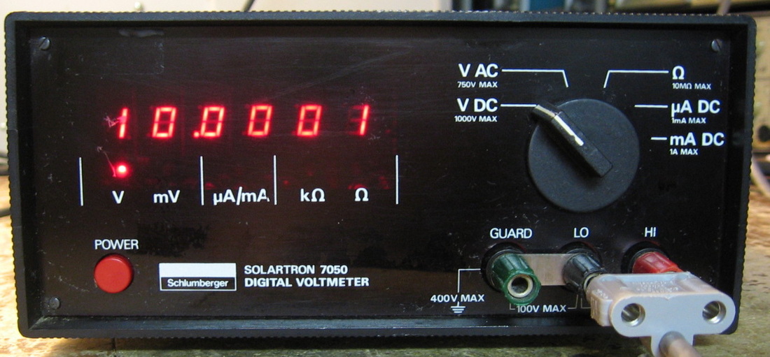
Solartron 7050: 5-1/2 digit DMM. As vanilla as it gets. I thought I would give Solartron another try since I was underwhelmed by their more expensive 7065 unit. This unit is actually not bad - just set the function and make the measurement. No other pesky controls to get in the way. The picture reveals some defects in the plastic front cover, but it looks a lot better in my dimly lit basement. (PDF) Grade: B+
Although correctly set to 115VAC when I received it, the plug was a 2-prong 230V European-style with an included USA adapter. I cut the cord and installed a normal 3-prong plug. Other than that, all it needed was a thorough calibration since it was way off (particularly bad for ohms). And while I was calibrating it, my Fluke 5200A AC calibrator broke, so I got to fix something after all.
Although correctly set to 115VAC when I received it, the plug was a 2-prong 230V European-style with an included USA adapter. I cut the cord and installed a normal 3-prong plug. Other than that, all it needed was a thorough calibration since it was way off (particularly bad for ohms). And while I was calibrating it, my Fluke 5200A AC calibrator broke, so I got to fix something after all.
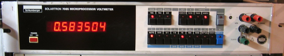
Solartron 7065: 6-1/2 digit DMM. Has some cute math functions, but otherwise is not as accurate as the HP 3455/6 series, despite Solartron's claim. I'm not at all impressed with this DMM. I guess that's why Solartron is not exactly a household name in test equipment anymore. (OM) Grade: B
This meter had a bad TR704 and a bad power switch. Those were easy. The hard part was bending back the front panel that looked like someone had hit it with a sledge hammer.
Postscript: I hadn't used this unit for a few years and when I finally did get around to turning it back on, I noticed that the 100K ohm and greater ranges were quite noisy. I spent a few fruitless hours trying to convince myself that the ohms current source was at fault, but voltage measurements across several of the resistors in the circuit were perfectly stable. However, measuring the voltage on the output jacks showed that they were varying. And that led me on another wild goose chase looking for noisy power rails. At one point, I thought I had cured the problem with a 0.1 uF capacitor on the 36V line. But then, without thinking, I lifted one end of the capacitor and tried it on the other voltage rails, namely 5V. My capacitor still had a 36V charge and discharging it on the 5V line made for very unhappy TTL chips. All the unit would subsequently do is continually reset. I lifted the reset pin of the MC6800 uP but it was to no avail - after a manual reset of the uP, the unit hung with a blank display. Figuring I must of blown out dozens of chips, it then occurred to me that the 5V digital P/S is isolated from the 5V analog P/S, and so I only could have blown out about 10 chips, not 50. Randomly probing around with a scope looking for non-TTL levels proved nothing. But then my hand felt a little warm as I passed over a couple of chips. Got out the Fluke IR thermometer and sure enough, two 74LS74s were about 135 degrees. Replaced those and the thing sprang back to life. Now for the noisy resistance measurements? I wasn't making a good connection across the sense and guard jacks. The thing is extremely sensitive, more than most of my DMMs, but it seems perfectly fine now.
Postscript^2: I spoke too soon, because this thing is still fluctuating in the 100K and greater ohms ranges. For instance, a 100K resistor will read anywhere from 99,970 and 100,000, with the fluctuation going steadily up and down over a period of a few seconds. Moreover, it would only be like this for certain orientations of my test leads. A bit of experimentation proved that it was a result of 60 Hz interference, and the fact that the fluctuating readings were periodic led me to believe that the 60 Hz synchronization of the A/D was not being done properly. A quick check of the various jumpers in the unit showed that it had been set to run off 50 Hz! So I correctly jumpered it for 60 Hz - and - it still fluctuated! The primary of the AC transformer is tapped and the 60 Hz line frequency goes through a PLL to sync the overall system clock (about 15 MHz). The scope showed that the PLL was not locking and a few hours of pointless replacement of ICs boiled it down to the real problem. The VCO in the PLL is controlled by two MV2110 varactors. I pulled them out and stuck two MV2109s in (about 3 pF lower than the MV2110s), since that is all I had. The PLL locked right up, the fluctuations are gone, and life is back to normal.
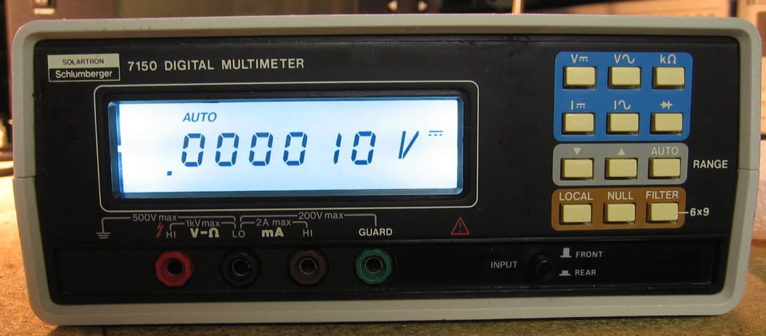
Solartron 7150W: 6-1/2 digit DMM. Well, it is really 5-1/2 digits, but for some functions and ranging, flicking the FILT button will give you 6-1/2 digits. Does all the functions: VDC, VAC, IDC, IAC, ohms, and diode, with nulling capability as the only "math" function. Mine is the "W" model and I have no idea what that means. Solartron made a 7150 and a 7150plus, that much I know. The specs are OK, about 30 ppm basic accuracy. People have tried to claim that the 7150 is a good alternative to the HP 34401A, but I don't believe that at all. A more fair comparison are the HP 3468/78 meters. The build quality is very nice, but Solarton did some stupid things. First of all, the power switch is on the rear panel - I absolutely hate that. I guess Solartron saved 25 cents by not running the usual plastic post from a front panel button to wherever the actual power switch is. Second, the minimum ohms range is 10K, so you can forget about seeing fractions of an ohm on the display. Third, the DCV input impedance is 10M for all ranges (the 7150plus version has a more reasonable 10G impedance for the two lowest ranges). And finally, you can only calibrate this thing over the GPIB bus. Moreover, before you can get the thing into cal mode, you have to insert a 2.5 mm shorting plug into a jack on the back. Gee, could you make it any more cumbersome? (PDF) Grade: B-
A few things were wrong with this meter upon receipt. The display backlight was very dark and the old yellow LEDs were replaced with super-bright white ones. The front/rear input switch was toast and was also replaced. Finally, the Schaffner line filter, which is known to be highly problematic in this series, was replaced as a precaution. The thing was also way out of calibration, so it was re-calibrated.
Solartron Bonus Rant: With this piece, I have now experienced the Solartron 7050, 7065, 7150W and the Guildline/Solartron/Schlumberger 9577 DMMs. With the exception of the 7050, which never claimed to be a great DMM, Solartron would have you believe they are wonderful, with performance equaling Fluke or HP. Simply not true. Not even close. Unless you can get one real cheap, they are not on my short list.
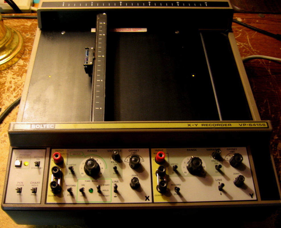
Soltec VP-6415S: This is an x-y plotter that can be used to make simple unannotated graphs. Many of my test equipment pieces have an output jack with a voltage proportional to what the equipment is measuring. Just hook that output up to the y-input of the Soltec, set the Soltec's internal time base to control the speed of the x-direction and plot away. For instance, use the Soltec in conjunction with a selective level receiver and plot signal power vs. time. Many pieces, such as the HP 3581C, also have an independent x-output jack. In that case, the Soltec can bypass its internal time base and use the external x-input. This can be used, for example, to obtain a plot of frequency response. Has a very nice electrostatic paper hold down mechanism and lots of control over x- and y- speeds and plot area. (--) Grade: B
As I recall, the plotter worked fine when I got it. I forgot I even had it for a few years and when I tried it recently, it didn't power up. The power switch had corroded, so I took it apart, cleaned it, and it should last until I turn it on again in a few years.
As I recall, the plotter worked fine when I got it. I forgot I even had it for a few years and when I tried it recently, it didn't power up. The power switch had corroded, so I took it apart, cleaned it, and it should last until I turn it on again in a few years.
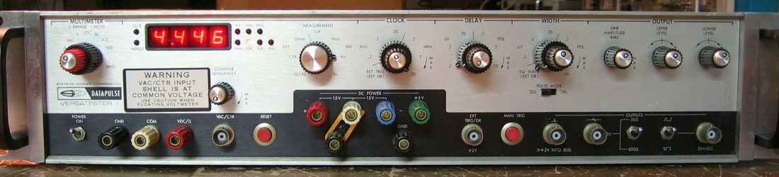
Systron Donner Datapulse Versatester: Don't know what they were thinking. Has a signal generator, a counter, a DMM and a 5/15/-15 power supply all at one incredibly low price! If I could sell this for even one dollar, I probably would. (OM) Grade: D+
The usual P/S capacitor problems and cold solder joints. But the real flaw was the defunct Voltage-to-Frequency converter, a nice sealed hybrid circuit which is, of course, unobtainable. So I built my own using some IC I got as a free sample from a manufacturer in France.
The usual P/S capacitor problems and cold solder joints. But the real flaw was the defunct Voltage-to-Frequency converter, a nice sealed hybrid circuit which is, of course, unobtainable. So I built my own using some IC I got as a free sample from a manufacturer in France.
T : Tekpower, Tektronix, Tenma, Topward, Transistor Devices, TrigTek, Triplett
Tekpower TP3016M: Handheld 50 watt switching power supply. Sold under a variety of names, this little P/S will do 0.3V-12V @ 0-3.75A or 0.3V-30V@ 1.6A with VC and CC control. Simple intuitive controls and a nice piece to have in a pinch for experiments. Will also supply 5V @ 2A out USB jacks on the front panel. Unfortunately, as many people have noted (and complained), there is no on/off switch - you must unplug it from the AC outlet to turn it off. Also (see the repair notes below), it will output -0.6V when the output is switched off (with the unit still powered up). (PDF) Grade: B+
These things are currently being sold with a street price of about $120. I bought one off of eBay for $20 with the description warning that the unit will only output about 100 mV regardless of setting. But I was betting it had to be something simple. Indeed, after verifying the seller's description (actually, the display showed 0.14V but the output was 0V), I found that the resistance across the two output jacks was zero ohms - not good! I took the thing apart and there is a Zener diode across the output terminals (probably for overvoltage protection of the DUT) and my guess was that the Zener was the offending part. And so it was, because after I removed, the resistance jumped up to about 50K. Put everything back together and presto - it still didn't work. One would press the output enable button only to have it light up momentarily as the output voltage jumped to 30V, and then immediately extinguish the light giving an output voltage of about -1V. Then it dawned on me that maybe the previous owner tried to calibrate it (you hook up an external DMM and punch in the readings) and essentially set the internal constants to nonsense (this is consistent with the erroneous 0.14V reading I first got on the display, despite the output being 0V). So I ran through the calibration and presto - works fine. Now the fact that I removed the Zener was what was letting the thing get past its nominal -0.6V with the output disabled. There is a published mod from the manufacturer that allows the supply to go back to 0V (remove a transistor and replace two capacitors with resistors). I found a couple of 50 ohm SMD resistors in the junkbox and did the mod. Much, much better now. I didn't have a Zener (and who knows what the value was anyway), so I tacked in a 1N4004, 400V, 1A diode across the output jacks. That at least will protect against inductive kickbacks or reverse polarity. I lose the overvoltage protection, and maybe someday I will tack on a 35V, 1W Zener in its place.
These things are currently being sold with a street price of about $120. I bought one off of eBay for $20 with the description warning that the unit will only output about 100 mV regardless of setting. But I was betting it had to be something simple. Indeed, after verifying the seller's description (actually, the display showed 0.14V but the output was 0V), I found that the resistance across the two output jacks was zero ohms - not good! I took the thing apart and there is a Zener diode across the output terminals (probably for overvoltage protection of the DUT) and my guess was that the Zener was the offending part. And so it was, because after I removed, the resistance jumped up to about 50K. Put everything back together and presto - it still didn't work. One would press the output enable button only to have it light up momentarily as the output voltage jumped to 30V, and then immediately extinguish the light giving an output voltage of about -1V. Then it dawned on me that maybe the previous owner tried to calibrate it (you hook up an external DMM and punch in the readings) and essentially set the internal constants to nonsense (this is consistent with the erroneous 0.14V reading I first got on the display, despite the output being 0V). So I ran through the calibration and presto - works fine. Now the fact that I removed the Zener was what was letting the thing get past its nominal -0.6V with the output disabled. There is a published mod from the manufacturer that allows the supply to go back to 0V (remove a transistor and replace two capacitors with resistors). I found a couple of 50 ohm SMD resistors in the junkbox and did the mod. Much, much better now. I didn't have a Zener (and who knows what the value was anyway), so I tacked in a 1N4004, 400V, 1A diode across the output jacks. That at least will protect against inductive kickbacks or reverse polarity. I lose the overvoltage protection, and maybe someday I will tack on a 35V, 1W Zener in its place.
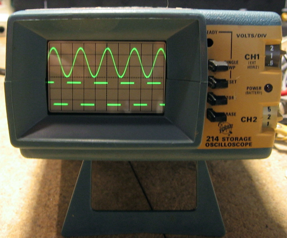
Tektronix 214: 500 kHz "micro" portable two channel oscilloscope. If you thought the Tektronix 323 was small (see next entry), the 214 is even smaller. Kind of an odd user interface in that most of the controls are along the right side including the time/div which is all the way at the rear and difficult to see. There are two probes integral to the unit - meaning you can't remove them, nor are there convenient BNC jacks. Runs off of AC or 10 NiCd AA batteries. The AC simply goes through a capacitive voltage divider to get it down to a voltage where it can be rectified and used to charge the batteries. Gee Tektronix, could you make it any cheaper (or more dangerous)? Changing the input AC line voltage requires you to change the divider caps (mine is currently incorrectly set for 100 VAC, 50 Hz). Build quality is so-so with lots of problematic transistor sockets and a very fragile switching P/S transformer. (PDF) Grade: C+
Advertised as "plugged in but nothing happened," I surmised that the batteries were toast. Normally in portable scopes like this, the batteries need to be functional because they act as the voltage regulator. So I took a chance and spent $45 shipped. When received, the batteries were indeed toast, but even worse, they leaked acid ALL OVER THE PLACE. Then of course, the seller, not knowing any better, applied AC voltage which instantly blew half the parts on the power supply board. I spend several hours replacing parts and finally got the P/S board up and running. The battery acid, in addition to destroying traces and component leads, also created some leakage paths on the board so that my -1000 VDC to the CRT was only about -600 VDC (this took a lot of time to find). Plugged the P/S board in, turned on the scope, and .... nothing on the CRT. The CRT did flash when I turned the unit off, so at least the CRT had some life. At one point, I did manage to see a trace, but it was short lived and depended upon what angle I held the CRT at. Unfortunately, the acid had corroded almost all of the connectors on the various boards as well as the socket on the CRT. I spend many hours removing the connectors and point-to-point wiring everything to the point that I am now getting a stable trace. At this point, I noticed that in two channel operation, the scope was not doing either alternate or chop like it was supposed to, but rather it seemed like it was adding the two channels. The trace switching is handled by an obsolete SN74L72 flip-flop and after I located a cheap one on eBay, that fixed the two channel problem. The only other problem seems to be that the scope will only trigger on channel #2. This presents no big problem in single channel operation (just use channel #2) and is also fine for two channel operation. To diagnose this problem requires disassembling the whole thing again - no thanks. The corrosion is so bad that the scope is hanging together by a thread. You will notice in the picture that the Power LED isn't lit. That's a result of moving some wires the last time I reassembled it. I currently have the unit operating off a 12V supply through two wires I've brought out of the cabinet. To make it operate on NiCds, I would have to change two expensive capacitors and buy 10 batteries. Given how tenuous all my repairs were, I don't think I am likely to do this. We'll simply call it a day and be satisfied that I brought back to life a piece which was virtually destroyed by the leaking batteries.
Postscript: After a few years, turned this on and .... nothing. I'm running it off of an external 12V supply and the supply showed zero current draw. I was ready to throw this in the "It's Dead, Jim" pile since the boards are extremely corroded and I had hard-wired all of the boards together (since the connectors were shot) making disassembly a chore. But I was able to fold back the power board and quickly found a defective Q235 that feeds the bases of the switching transistors in the pseudo-switching 214's power supply. A new 2N3906 restored the unit to whatever rotten shape it was in previously.
Mini Tektronix Bonus Rant: I haven't worked much on Tektronix equipment in the last few years, but one thing led to another and five of the last eight pieces I've acquired have been Tektronix scopes. This reminded me of how I absolutely detest working on Tektronix stuff, especially in comparison to HP or another major manufacturer. Tektronix may have had excellent state-of-the-art circuit designs (probably true), but their early stuff is crammed into the cabinet with little regard for future serviceability (definitely true). Maybe they should have made their engineers try and fix their stuff before they paid them! I guess ultimately I can't completely fault Tektronix. I mean, weren't there a few automobiles where the engine had to be partially removed to change a spark plug?
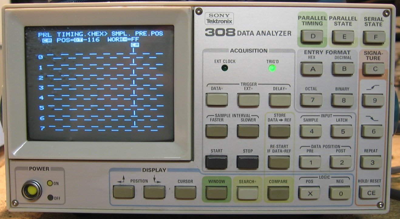
Tektronix 308: 8-channel, 20 MHz "data analyzer" (logic analyzer) with parallel timing, parallel state, serial (up to 9600 bps) and signature analysis modes. Due to its low clock rate, this piece is useful generally only for vintage pieces, say 1985 or earlier. And with only 8 parallel timing channels, you aren't going to be looking at 16-bit processors any time soon. My intended purpose with the 308 is to look at discrete combinatorial TTL and CMOS chips. The biggest advantage of the 308 is the size. Although relatively deep, the height and width are about the size of a paperback book. With my limited bench space, I find my usual logic analyzers (HP 1630, 1650, 16500) simply too big to sit next to the piece I am debugging. Of course, the capabilities of the 308 pale in comparison to those HP logic analyzers, but it will be good enough for my needs. One nice feature of the 308 is that it has a signature analyzer mode. This operates exactly like my HP 5006A and 5005B and people have reported they get the same results with the 308 as with the HP models, although I haven't yet tried it. I picked this unit up for $67 shipped which is a good price. What is even better is that it came with not one, but two P6451 data probes and a P6406 word recognizer probe. And the probes had the terminal blocks, all the wires, and all of the minigrabbers. Plus it came with a front cover and the instruction manual. So whoever owned this piece was very careful with it. (PDF) Grade: B+
This piece was in pristine condition, inside and out, except for the plastic CRT cover which had some sort of chemical splashed on it in the past. This left a bunch of little white polkadots scattered around. I replaced it with a clear piece of acrylic (picture shows the original CRT cover).
This piece was in pristine condition, inside and out, except for the plastic CRT cover which had some sort of chemical splashed on it in the past. This left a bunch of little white polkadots scattered around. I replaced it with a clear piece of acrylic (picture shows the original CRT cover).
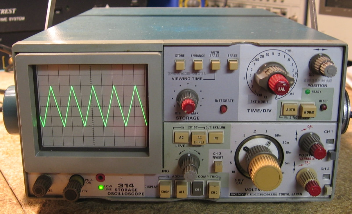
Tektronix 314: Dual channel, 10 MHz storage oscilloscope. Slightly larger than the Tektronix 323 (see below), it is a portable scope that can be run on AC or externally with 12 VDC or 24 VDC (switch selectable). Not much to say about it other than it is a good example of just how much stuff Tektronix managed to cram into a small chassis. (PDF) Grade: B+
This piece was a bit of a gamble since the seller's description said "powers up, no trace." I generally don't like to buy scopes like that because "no trace" could mean that the CRT is shot. But it was only $25, so I took a chance. When received, there was a very nice baseline trace seen on the CRT. So what did the seller mean by "powers up, no trace"? Well, there was no vertical deflection when you hooked up a signal to the input - that's what "no trace" meant. A quick check of the P/S voltages showed all correct except for the 100 V which was reading 0 V; the 100 V is what powers the vertical deflection transistors (duh). An ohmmeter revealed a 7 ohm short to ground on the 100 V rail which usually means a (nearly) shorted electrolytic or tantalum capacitor somewhere. By disconnected certain cables, I was able to determine that the short was within the P/S and it had to be the single 3 uF, 150 V electrolytic near the output. Now getting the P/S board is a prime example of how just awful Tektronix was in terms of serviceability. One has to almost completely disassemble the scope, including pulling the CRT, to get the P/S board out. When I finally did, and replaced the exploded capacitor, I noticed that leaking electrolyte had actually dissolved the trace on the 100 V line. So the only thing seen looking back on the 100 V output was just a shorted capacitor. Anyway, a new capacitor and a careful cleaning of the horizontal timebase cam switch and the 314 now performs flawlessly.
This piece was a bit of a gamble since the seller's description said "powers up, no trace." I generally don't like to buy scopes like that because "no trace" could mean that the CRT is shot. But it was only $25, so I took a chance. When received, there was a very nice baseline trace seen on the CRT. So what did the seller mean by "powers up, no trace"? Well, there was no vertical deflection when you hooked up a signal to the input - that's what "no trace" meant. A quick check of the P/S voltages showed all correct except for the 100 V which was reading 0 V; the 100 V is what powers the vertical deflection transistors (duh). An ohmmeter revealed a 7 ohm short to ground on the 100 V rail which usually means a (nearly) shorted electrolytic or tantalum capacitor somewhere. By disconnected certain cables, I was able to determine that the short was within the P/S and it had to be the single 3 uF, 150 V electrolytic near the output. Now getting the P/S board is a prime example of how just awful Tektronix was in terms of serviceability. One has to almost completely disassemble the scope, including pulling the CRT, to get the P/S board out. When I finally did, and replaced the exploded capacitor, I noticed that leaking electrolyte had actually dissolved the trace on the 100 V line. So the only thing seen looking back on the 100 V output was just a shorted capacitor. Anyway, a new capacitor and a careful cleaning of the horizontal timebase cam switch and the 314 now performs flawlessly.
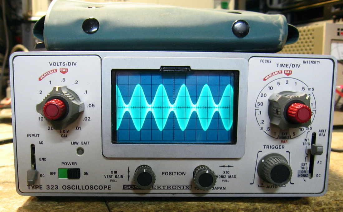
Tektronix 323: 4 MHz "mini" portable oscilloscope. What else can you say except it's so cute! I simply couldn't resist dropping $50 for this scope which also included two probes in the pouch sitting above it. It's only single channel and will trigger up to about 7 MHz with auto peak-to-peak triggering, but the main advantage of the 323 is that it will operate for several hours off of its internal NiCd rechargeable battery pack. And of course, it is so tiny that moving it around the lab is a joy. I think I might actually use this scope for simple tasks like checking TTL/CMOS sequential logic - I can put the scope real close to the circuit I'm testing. The 323 was the first development project for the new Tektronix-Sony joint partnership (which got past Japanese trade restrictions in 1965), and there is not a spare inch of space inside. Fortunately, the 323 doesn't use the ubiquitous cam-switches for the V/div and Time/div functions, just ordinary wafer switches which are much more easily cleaned. But Tektronix couldn't keep their hands off of the design as evidenced by the myriad number of shafts, couplers, brackets and unique small parts that are typical of the "genius" mechanical engineers at Tek (see the Tektronix Mechanical Bonus Rant below the Tek 2230 entry below). I mean, how else can you explain the mechanical parts list which has about 280 parts spread over 8 pages! Shown in the picture is the 323 displaying a 1 kHz AM modulated RF signal from one of my signal generators. (PDF) Grade (primarily for cuteness): B+
Advertised as condition unknown due to no AC power cord. And that's perfectly understandable since the receptacle is of a type I've never seen. But the 323 has a pair of banana jacks for an external DC power supply, so it was simple to get the thing powered up. Due to probably years of dormancy, all the switches and pots needed a thorough spray of contact cleaner. The six NiCd C-cells were discharged and most likely would hold some sort of charge (I hooked them up for a few hours to a 100 mA current source), but at least one cell had leaked out the white crusties, so a new set of batteries (sub-C) were installed. Electrically, everything seemed to work fine except for the low battery voltage warning neon on the front panel which didn't light when I turned the voltage on the external P/S down to 6 V. When this is supposed to light up, there is 100 V feeding the neon through a 1 megohm resistor. That's not a whole lot of current, so I paralleled in a 270 K resistor and now the neon lights properly. Maybe at some time, the bulb was changed from the original lower current bulb. I did a minor tweak of some of the calibration pots and wired up a power cord using Molex pins from a defunct PC P/S so that I can charge the batteries while they are in the 323.
Advertised as condition unknown due to no AC power cord. And that's perfectly understandable since the receptacle is of a type I've never seen. But the 323 has a pair of banana jacks for an external DC power supply, so it was simple to get the thing powered up. Due to probably years of dormancy, all the switches and pots needed a thorough spray of contact cleaner. The six NiCd C-cells were discharged and most likely would hold some sort of charge (I hooked them up for a few hours to a 100 mA current source), but at least one cell had leaked out the white crusties, so a new set of batteries (sub-C) were installed. Electrically, everything seemed to work fine except for the low battery voltage warning neon on the front panel which didn't light when I turned the voltage on the external P/S down to 6 V. When this is supposed to light up, there is 100 V feeding the neon through a 1 megohm resistor. That's not a whole lot of current, so I paralleled in a 270 K resistor and now the neon lights properly. Maybe at some time, the bulb was changed from the original lower current bulb. I did a minor tweak of some of the calibration pots and wired up a power cord using Molex pins from a defunct PC P/S so that I can charge the batteries while they are in the 323.
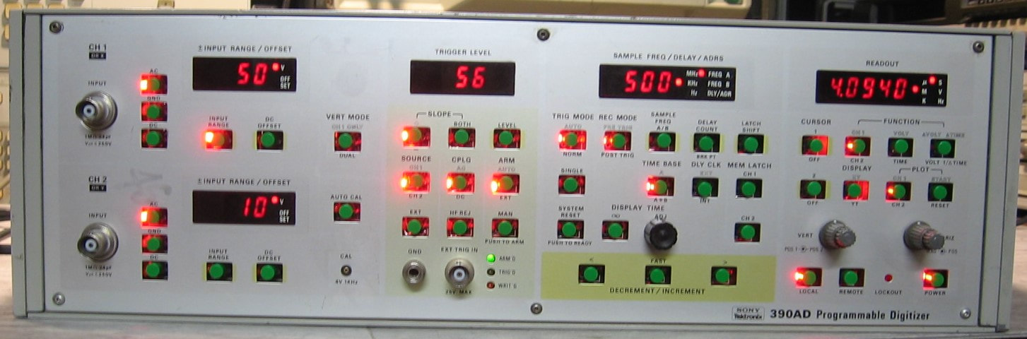
Tektronix/Sony 390AD: Two-channel, 30 MHz digitizer. Think of this piece as a two-channel oscilloscope without the display. The 390AD has controls for vertical gain/offset, horizontal timebase, and various trigger levels/options, just like a real scope. It acquires 2,048 10-bit samples per channel at up to 30 Msamples/sec (everything can be doubled if one only uses a single channel). The captured waveforms can be output to an x-y display, an x-y plotter, or over GPIB. This piece was manufactured in the early 1980's by Sony - by the late 1980's, Tek had come out with the much more capable RTD-710 model that sampled at 200 MHz and had 256K of memory. Of course, once real digital oscilloscopes came out, these pieces were pretty much dinosaurs especially given the $14.5K retail price in the 390AD's last years. My price was substantially lower, however: twenty bucks. The 390AD has a somewhat incomprehensible front panel and a consult with the operating manual is mandatory. But it seems to do what it was intended to do, despite drawing 200 watts to do it! (PDF) Grade: B
Advertised by a big-name test equipment dealer as failing to respond to input signals, intermittent lockup of controls, and intermittent power cycling. I naturally expected to find a power supply problem, but the voltages (+5, -5, +15, -15, +60, -60) at the nicely labeled test points were all perfect. What I did find was that a lot of the front panel buttons were completely shot. Only a few of them seemed to work. I got enough working and fed in a signal. The digitization went fine and the x-y display on the attached oscilloscope looked fine also. I kept exercising all of the buttons over the next day or two and they seemed to get better with use. All of them now work, but a few need to be pressed just right to make contact. I did pull the front panel off to take a look and discovered that a previous owner had done the same, as evidenced by the two missing screws which I later found wedged across a few contacts on the edge connectors on the motherboard! I'll keep an eye out for replacement switches, but these seem to be custom jobs that have an integrated LED.
Postscript: A few years have gone by and when I started this piece up to see if it still works, it would not power on. And that was because the power button (soft-start) was toast. I jumpered over the switch to get the unit to turn on and found that pretty much all 47 front panel pushbutton switches were bad. These are special LED-lit odd-sized Tektronix switches and have long since been unobtainable. Since the 390AD is totally useless if I can't control it from the front panel, I went on eBay and ordered 50 6x6 mm tactile switches w/caps and 50 red LEDs from China. It took me about 6 hours to dissect the 390AD, remove all the switches and solder the new switches in. I had to carefullly snip off two leads of each switch and bend the remaining leads to fit the hole spacings in the board, and I had to bend the LED leads in 6 places to fit them adjacent to each switch without shorting anything. The result is shown in the photo. It's not going to win any awards, but at least now the 390AD is functional. Total cost was less than ten dollars. I dissected one of the faulty switches and it was not the little carbon pad that bridges the contacts that went bad; it was the rubber membrane that held the carbon pad that tore. The resistance of each switch was highly variable with finger pressure, but a lot of them were in the 10 Kohm range with a normal touch. Since these are being used to the input of TTL logic chips by grounding a pull-up resistor that was about 8 Kohm, no wonder they didn't work.
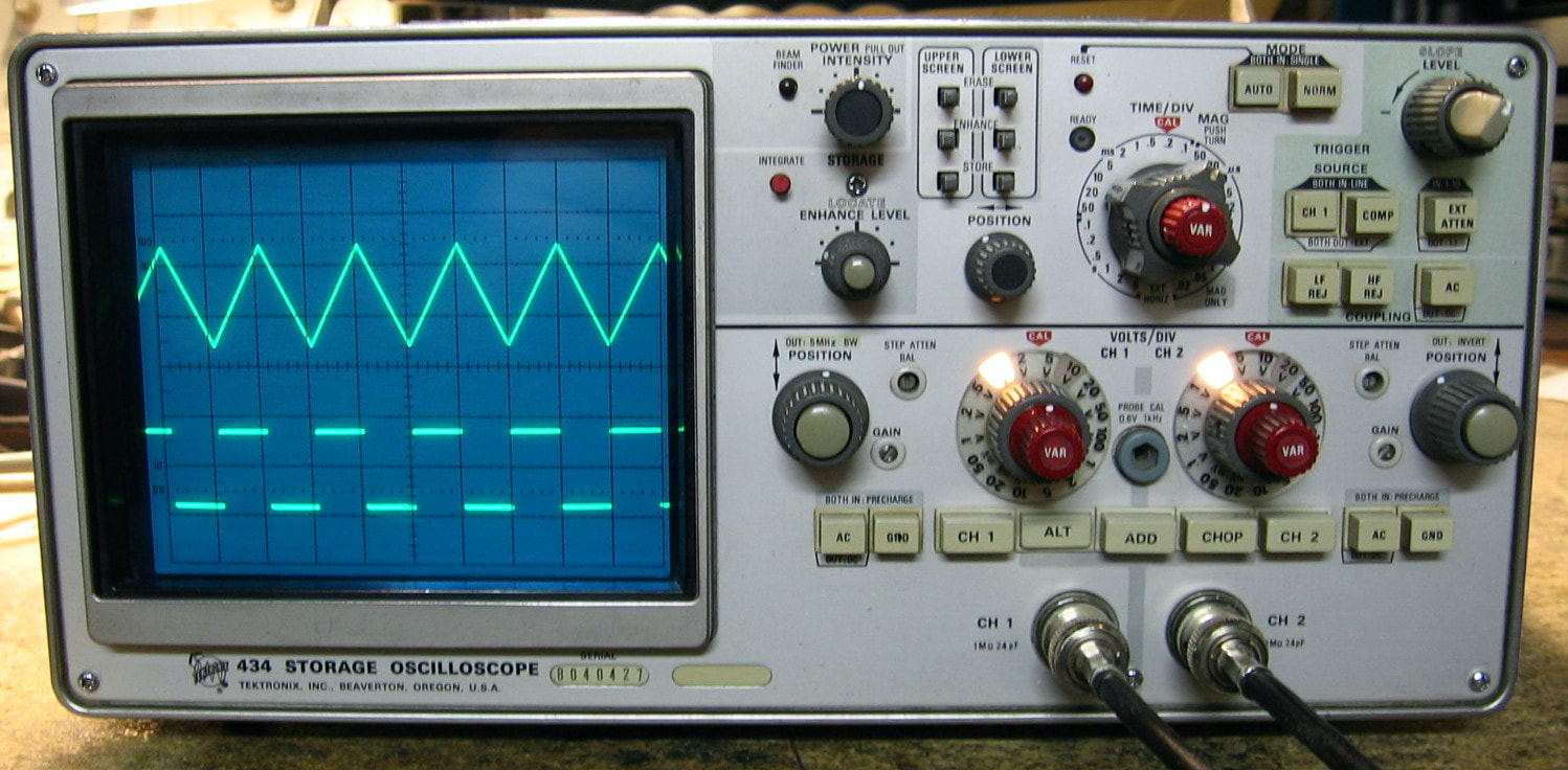
Tektronix 434: 25 MHz analog oscilloscope. Besides being a perfectly ordinary scope, the 434 uses a storage CRT with separate upper-half and lower-half sections. As with all storage CRTs, it takes a bit of twiddling to get the contrast just right. It is particularly useful when running the scope in single acquisition mode and will capture and store best with time bases >10 usec. I bought this unit right after the Tek 2230 (see below) which was a bear to work on. The 434 is reputed to be the worst mechanical design Tektronix ever produced, so I had to see for myself. It isn't as bad as I thought, but then again, I didn't have to remove any boards (that's where the fun begins). Otherwise, it is pretty boring. (PDF) Grade: B
Advertised as powers up, shows a trace, untested, I plopped down $60 so I could enjoy the insanity of the Tektronix mechanical engineers (see the Tektronix Mechanical Bonus Rant beneath the description for the Tek 2230 below). It did power up, but all I saw was a dot on the screen - there was no sweep. At first I thought it might be the tunnel diodes used in the trigger circuit, but I was able to prove that was not the case. No, there was also a problem with the single sweep and everything pointed to a problem with the sweep reset circuit. It was though the scope thought it had just completed a single sweep, but never reset the circuit. After hours of poking around and testing parts, I looked up and the trace/sweep was suddenly there! I have no idea why, except maybe I disturbed a cold solder joint with all of my machinations. Anyway, everything behaved properly except the time base was off by a factor of 10 for the 1 us through 50 us settings. The timing capacitors tested OK, so that, unfortunately, led me to the main timing cam switch. I had cleaned dozens of these things in my Tek 7000-series plug-ins, so I knew the drill. Except when I removed the cover, it looked like someone had poured varnish on the circuit board beneath the cams - several were fused open or fused shut. It is amazing that any of the time bases were correct. So with the help of some acetone and some dental picks, I managed to get the cam switch fully functional. For how long, I can't tell you. Then I ran through the calibration procedure and everything adjusted nicely.
Advertised as powers up, shows a trace, untested, I plopped down $60 so I could enjoy the insanity of the Tektronix mechanical engineers (see the Tektronix Mechanical Bonus Rant beneath the description for the Tek 2230 below). It did power up, but all I saw was a dot on the screen - there was no sweep. At first I thought it might be the tunnel diodes used in the trigger circuit, but I was able to prove that was not the case. No, there was also a problem with the single sweep and everything pointed to a problem with the sweep reset circuit. It was though the scope thought it had just completed a single sweep, but never reset the circuit. After hours of poking around and testing parts, I looked up and the trace/sweep was suddenly there! I have no idea why, except maybe I disturbed a cold solder joint with all of my machinations. Anyway, everything behaved properly except the time base was off by a factor of 10 for the 1 us through 50 us settings. The timing capacitors tested OK, so that, unfortunately, led me to the main timing cam switch. I had cleaned dozens of these things in my Tek 7000-series plug-ins, so I knew the drill. Except when I removed the cover, it looked like someone had poured varnish on the circuit board beneath the cams - several were fused open or fused shut. It is amazing that any of the time bases were correct. So with the help of some acetone and some dental picks, I managed to get the cam switch fully functional. For how long, I can't tell you. Then I ran through the calibration procedure and everything adjusted nicely.
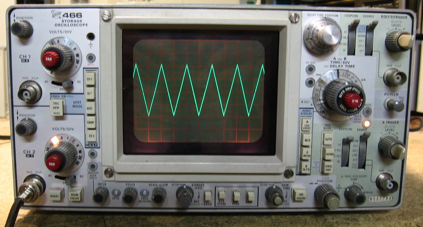
Tektronix 466: 100 MHz storage oscilloscope. If you practiced electronics in the 1970s or 1980s, chances are you used one of the Tektronix 400 series oscilloscopes. I can't think of too many other pieces of test equipment as ubiquitous as these except perhaps the Simpson 260 VOM or the HP 8640B signal generator (if you did RF work). My particular scope is the storage version of the classic Tek 465. It's pretty much everything you would expect of a 100 MHz dual-channel analog scope, so no need to bore you with the details. (PDF) Grade: B+
I bought this for $50 in condition unknown, other than the picture showing a trace on the CRT. When received, I turned it on and started exercising the controls to see what worked and what didn't. A few minutes later, the CRT went blank and I smelled something burning. A visual inspection revealed nothing, and when I powered it back up, the power supply voltages were OK and the scope ran fine - it's been running for days without anything burning. So if something popped, it must have popped open. Maybe I'll see the effect of that, perhaps not. The scope basically worked except there were three minor problems. First, the delay position 10-turn pot was extremely noisy, so it was removed, dissected, cleaned and reinstalled. Second, some previous owner must have set the scope on its front panel which put all of the weight on the two V/div variable knobs and the time/div variable knobs, which transferred the weight onto the potentiometers on the circuit board. In the case of the two V/div pots, all that did was to bend them slightly off the board - no big deal. But the time/div variable pot was nearly sheared off and when I removed it, the pot measured infinite resistance. The pot was one of those black, square, ganged job with the back portion containing two switches and the front portion a standard 50K. I managed to find a 20K pot in a spared Tek 7B53A plug-in, so I used that. There is about 50V across the pot, so I think the 20K will survive at about 1/8-watt. The third problem was the channel #1 lost the signal input at 2, 0.2, and 0.02 V/div settings. This led me on a whole day wild goose chase on the attenuator board. At one point, with all components removed from the board, I was measuring 7 ohms resistance from an isolated trace to ground! Bottom line: when I finally pulled the now empty circuit board away from the aluminum mounting structure, out popped a tiny washer. Somehow, somewhere this "shorting" washer found its way onto the board and then hid itself under the mounting. Everything now seems to work fine, although I'm sure the 466 could benefit from a complete calibration. Not something I'm looking forward to given that it is about 50 pages long.
Postscript: Did some minor tweaking of the adjustments in the attenuators and the sweep timings and the 466 is now pretty accurate. Adjusting the fast storage mode, however, is not for novices. I think I have it as good as it is going to get. All these Tek storage scopes are a huge pain in the ass to set up right and operate. Of course I have perfectly good digital scopes if I ever need to "store" a waveform.
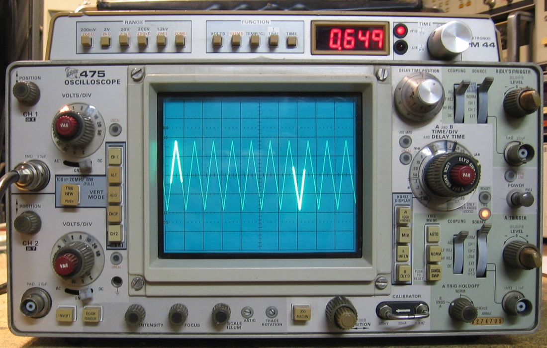
Tektronix 475/DM44: 200 MHz dual-trace, dual-timebase analog oscilloscope with 3-1/2 digit DMM option. I already had the Tektronix 466 100 MHz scope which is the variant of the 465 with a storage CRT. The 475 is an improved version of the 465 with twice the bandwidth (Tek also made a follow-on 475A with 250 MHz bandwidth). The only reason I bought the 475 was that I bought another one a couple of years ago which turned out to have a broken CRT (see the "It's Dead, Jim" section below). At that time, I stripped out all the boards and parts from that dead unit and threw everything in a box in my basement. Presently, I saw another 475 on eBay whose listing photos at least showed a working CRT, so I thought I should be able to fix anything else wrong with it from my collection of spare parts. I was right. The optional DM44 is basically a 3-1/2 digit DMM that will do DCV, ohms and Temp (with a probe) and has an appalling 0.1% basic accuracy. But Tektronix was very clever with this option because they hooked it into the dual timebase circuitry of the scope. So you can set a second intensified portion of a delayed trace and use the knob and readout on the DM44 to tell you the time interval (as shown in the picture). As I've mentioned numerous times on this website, I despise the mechanical engineering of early Tektronix scopes. But Tektronix really did know how to do circuit design. (PDF) Grade: A-
When received, basically nothing worked correctly on this scope. As problems were diagnosed and repaired, the channel switching didn't work, the dual-timebases didn't work, the DM44 didn't work, and on and on. I'll spare you the journey, but here's the outcome:
1) There would be a sort of correct trace on the screen for about 10 seconds on a cold start up, then the vertical deflection would halt. I replaced the vertical amplifier board with my spare; 2) The dual trace function didn't work. Turn on both channels and only get one. This was the result of a faulty SN7474 latch feeding the custom hybrid IC that controls the channel selection; 3) The dual time base didn't work. This was traced to a faulty Tek custom selected FET that is part of the trigger delay control circuitry. When I went to replace the FET with my spare, I noticed that the faulty FET was installed backwards and so the gate (pin #1) was being swapped with the source. Not good and no wonder
it blew up; 4) The V/div knobs didn't function correctly on both channels. There are four Tek custom hybrid attenuators on each channel. One was defective and the other seven benefited from an alcohol rub of their contacts; 5) The DM44 multimeter was giving nonsensical readings. This was traced to a faulty Signetics LD110 chip. Fortunately, the same IC was used in my earlier spare DM43; 6) The B-trigger pot/switch had no effect on the delayed trigger and, in fact, a wire had broken off of the pot and the ganged switch was showing infinite resistance. The pot/switch was replaced with one of my spares. In summary, that's six completely independent faults in one piece. I think that is some kind of record for me. Not to mention the necessary contact cleaner sprayed in all the accessible switches and pots. Finally, I went through the calibration procedure and everything adjusted normally.
Postscript: A couple of days after the repair, I had the covers off to check a calibration step and I heard some crackling followed by smoke wafting out the top. The smoke was coming from underneath the large silver-can electrolytic filter capacitor on the 50V unreg line. I yanked out the offending capacitor only to find leaking electrolyte all over. The cap was replaced with the one on my spare board and when I fired the scope back up, I saw a blob of purple arcing light shining through the underside of the board. So I yanked out the new capacitor and saw that the leaking one had left some carbonization that was bridging traces. After that was scaped away and the capacitor reinstalled, everything worked fine. Or did it? Suddenly, I had no trace on the CRT. I checked the -2450V cathode voltage and it was about -700V. But it was slowly ramping up to the desired -2450 volts. After about two minutes, the voltage was correct and the CRT was showing a trace. The longer I left the scope powered down, the longer it took for the cathode voltage to ramp up to the correct value. Sounded like a marginal capacitor somewhere in the cathode P/S which is a switching supply. To make a long story short (about 5 hours of debug time), the problem was a marginal solder joint on R1303 which is a Tek hybrid resistor package. This marginal connection became erratic which caused the cathode voltage not to ramp up nicely, but to gyrate randomly. The cathode switching power supply starts at the base of a transistor which is supposed to sit nominally at about 0.7V. The resistor package has 110V on one side and -2450V on the other which provides the feedback and keeps the supply in regulation. With the erratic solder joint, the base voltage was erratic and the feedback from the resulting erratic secondary of the supply only made it worse. A touch up with the soldering iron cured all ills.
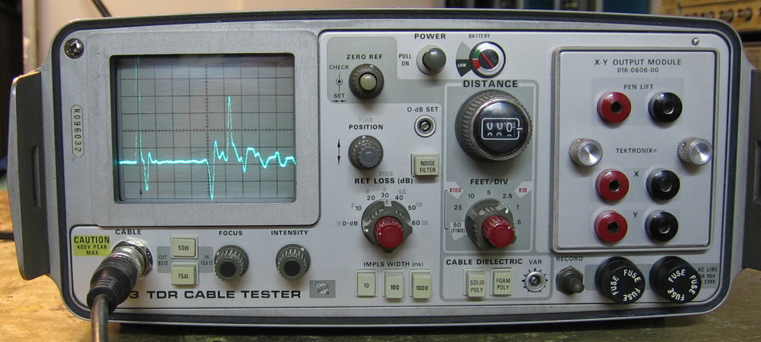
Tektronix 1503: Time Domain Reflectometer used by cable maintenance crews forever. This one is much better than the HDW T2000 I also have since it will output a 10 ns test pulse. The Tek 1502 is similar, but operates over a shorter range. However, only the Tek 1502 has a custom tunnel diode that cannot be obtained (Tek actually sliced it open and modified it), so I'm happy with the longer range, lower resolution, slightly more impractical 1503. One of my better buys at a mere $14.99 + shipping. (PDFs courtesy WA1MIK) Grade: A-
This was your typical "doesn't power up" eBay listing. However, with Tek TDRs, all that usually means is that the battery is toast (it runs the P/S through the battery). In my case, the battery was not even present. The rumor is that you can run the 1502/3 off of AC if you fool it into thinking it has a battery with a 2,200 uF cap in parallel with a 200 ohm resistor across the battery terminals. The rumor is true and the 1503 runs like a champ. Now, let me take this opportunity not only to condemn the Tektronix mechanical engineers for their needlessly complex designs, but also the authors of their calibration procedures. The right way to do cal is the way HP does it - for each subprocedure, tell you what you are trying to do, tell you the instrument settings, and suggest the external equipment. But not Tektronix. They only tell you what Tek pieces to use and what dials on them to set. So if you don't have them, you have to figure out what the pieces are doing and then search around the lab for something suitable. OK, I suppose that's not too bad. But then they tell you how to set the controls of the piece you are calibrating, and you march your way through the various subprocedures. God forbid you miss or skip a step. Because most often, the instrument needs to be set a certain way and that way was described initially 50 steps ago and modified 10 times since that in the previous procedures. Simply atrocious. Rant completed.
This was your typical "doesn't power up" eBay listing. However, with Tek TDRs, all that usually means is that the battery is toast (it runs the P/S through the battery). In my case, the battery was not even present. The rumor is that you can run the 1502/3 off of AC if you fool it into thinking it has a battery with a 2,200 uF cap in parallel with a 200 ohm resistor across the battery terminals. The rumor is true and the 1503 runs like a champ. Now, let me take this opportunity not only to condemn the Tektronix mechanical engineers for their needlessly complex designs, but also the authors of their calibration procedures. The right way to do cal is the way HP does it - for each subprocedure, tell you what you are trying to do, tell you the instrument settings, and suggest the external equipment. But not Tektronix. They only tell you what Tek pieces to use and what dials on them to set. So if you don't have them, you have to figure out what the pieces are doing and then search around the lab for something suitable. OK, I suppose that's not too bad. But then they tell you how to set the controls of the piece you are calibrating, and you march your way through the various subprocedures. God forbid you miss or skip a step. Because most often, the instrument needs to be set a certain way and that way was described initially 50 steps ago and modified 10 times since that in the previous procedures. Simply atrocious. Rant completed.
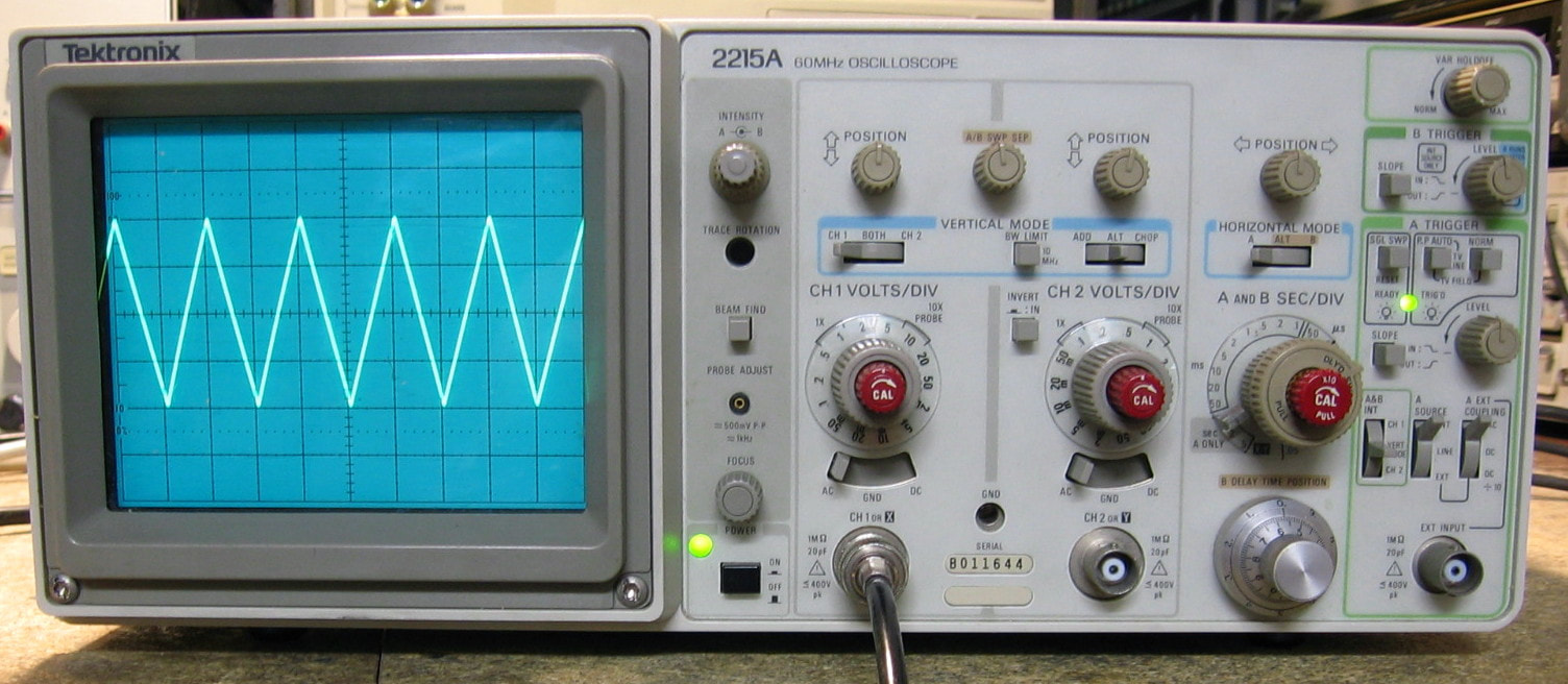
Tektronix 2215A: 60 MHz analog oscilloscope. I used to have a Tektronix 2213A scope but gave it away to a pal a couple of years ago. Too bad because the V/div knobs are the same as in my Tek 2232 and my repair of the latter's knob failed over time. So rather than spend $30 for a new knob/shaft, I bought a broken 2215A for $50 which, of course, has two knobs! But as long as I have it, I might as well fix it. And it is a little better than the 2213A because it has a dual time base. I won't bore you with the specs - Tek sold a zillion of the 2200-series scopes and almost everybody has one. (PDF) Grade: B+
This scope came from the Physics Department of a university and was advertised as "won't focus." That typically means one (or more) of the six 510K resistors in the HV supply to the control grid of the CRT has opened up. And that was exactly the case. All six resistors were replaced (which required drilling out two frozen screws holding the P/S shield in place) and I fired the unit up. It seemed to basically work except that the V/div settings were extremely noisy. So I pulled the vertical board out (a job and a half) and did the usual cleaning on the cam switches. That cleared up all the noise and everything worked with the single exception of the trigger slope button - it would only trigger on a positive slope, not negative. After verifying the front panel switch was OK, a quick glance of the schematic led me to U460, a CA3102E dual differential amplifier. The inputs to the IC were all fine, but the outputs disappeared the moment the slope was set to negative. The CA3102E is obsolete, but there are a few out there for a few dollars apiece, so I ordered three of them (Tek used this IC in several places in the 2215A) just in case. And while I was waiting for these to arrive, I came across one in my junkbox (from a board of the HP 3325A). In it went and the 2215A is all fixed.
Postscript: I have seen on occasion some ~25 kHz oscillations (from the switching P/S?) on the 2 mV/div and 5 mV/div scales with nothing connected to the input. It is much more noticeable on channel #1 than channel #2 and seems to abruptly go away if I twist the scope's metal frame a bit. I did notice a little spring clip at the rear of the CRT's shield that serves presumably as a ground. There was some corrosion there so I filed the clip and shield a bit. Magically, the oscillations went away.
Postscript^2: Preemptively replaced the two Rifa 0.0022 uF Y-capacitors with non-Rifa 0.0015 uF Y-capacitors in the power supply.
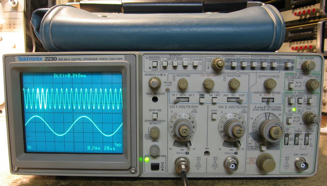
Tektronix 2230: 100 MHz Analog/Digital oscilloscope. This scope is similar to my Fluke/Phillips PM3390B Combiscope (although not as good) and contains both a standard analog scope and a digital storage scope. The sampling rate, however, on the digital side is only 20 MHz, so even though the front-end has a bandwidth of 100 MHz, you have to wait a bit for the sampling to catch up and fill in the waveform. I won't bore you with the specs, but suffice it to say that Tektronix always did know how to build a good scope. While the analog side operates pretty much as one would expect, there is no way to take advantage of all the menus that control the digital side without consulting the manual. And like the Tektronix 2754P spectrum analyzer described below, there are a couple of odd buttons that seem non-standard and highly specific to a particular function. My (broken) unit came complete with the accessory pouch, two pretty well used probes, the operator manual, a 30-minute VHS tape describing the operation, and an invoice from Tektronix in 1989 describing repairs to the P/S made three weeks after the unit was sold. Quality control, Tektronix? Not bad for fifty bucks. I would normally give the 2230 a grade of A-, but I'm knocking some off for the needless complexity and difficulty in servicing. (PDF/OM) Grade: B+
The unit was advertised by a non-equipment dealer as powering on and off as though someone was repeatedly pressing the power button. Most Tek scope power supplies have loads of protection circuitry and this symptom is the hallmark of a supply that is trying to start up and then quickly shut down by the protection function (and the cycle repeats indefinitely). After about an hour of careful dissection, I arrived at the supply and everything looked good visually. The supply consists of a switching "pre-regulator" that delivers 43 VDC. This goes to a second switching inverter which produces all the required voltages on its secondary side. I unhooked the MOSFET in the pre-regulator and hooked up an external 43 VDC power supply. As I cranked up the voltage, my external supply went into current-limiting at about 37 VDC. The 2230 has an overvoltage protection circuit consisting of a 51 V Zener diode and an SCR. So I pulled out the SCR and cranked up the voltage to 43 VDC. The scope seemed to work fine at this point. So I put back the MOSFET, plugged the unit into the mains and let her rip. What I got on the screen was an unfocused blob of stuff. I checked the 43 VDC pre-regulator output and it was less than 35 volts. All the final DC voltages were also about 25% low. It then dawned on me to check the 145 VDC coming out of the first diode bridge (off the AC line) and it, too, was way low. Bottom line is that the main electrolytic capacitor was completely open. So, 1) the cap was replaced, 2) the 51 V Zener diode (which must have been leaking) was replaced with a pair of diodes totaling 56 V (there was a Tek mod raising the Zener spec), 3) the MOSFET Molex connector was cut and the wires soldered directly to the transistor (another published Tek mod), and 4) the fan was dissected, cleaned and re-installed with a little hot-melt glue (the fan had broken off of its mounting bracket and was sitting loose in the supply). All is not quite perfect, however. The trigger level control is a dual pot/switch gizmo with the inner shaft switch setting the HF reject on/off. The switch is completely jammed into the reject on position. This puts base voltage on a transistor which switches a capacitor into the trigger signal. I simply shorted E-B on the transistor to permanently leave the HF reject off. Not a big issue. Even if I ever located a replacement pot/switch, I'm not sure I want to spend hours pulling off the front panel.
Postscript: I did find a (new) replacement trigger pot/switch for fifteen bucks, so how could I resist? Took about five hours to disassemble the unit, replace the pot, reassemble the unit, disassemble the unit and fix all of the stuff I broke on the first try, reassemble the unit, etc.... I managed to dislodge one of the lever switches, and although I thought I reassembled it correctly, it acts a bit flaky. I have three (used) switch assemblies on order, so it looks like I get to disassemble the thing yet again! I'll probably break something else.
Postscript^2: As alluded to in the previous postscript, I did manage to break the horizontal mode lever switch in my previous repairs to replace the HF reject switch. While waiting for my replacement lever switches, I decided yet again to pull the front panel and see what the problem was. I desoldered the lever switch and dissected it. After bending the contact fingers straight again and filing down the corroded contacts, the switch seemed fine and was reinstalled. I took a few "shortcuts" from the service manual to get the front plastic panel off. But the whole operation still took about three hours.
Postscript^3: Preemptively replaced the two Rifa 0.0022 uF Y-capacitors with non-Rifa 0.0015 uF Y-capacitors in the power supply.
Tektronix Mechanical Bonus Rant! As I have mentioned several times elsewhere, the mechanical engineers at Tektronix were certifiably insane and should all have been committed to asylums. And the 2230 should be in a special showcase in the lobby of the asylum so visitors could see just why the engineers were locked up. This piece has to be at the top of the list of difficulty in servicing. But even if you can follow the (often incorrect) 50-step procedure to do something simple like pull the front panel off, you are greeted by an endless collection of special brackets, clips, extension shafts, weird connectors, cover plates, support frames, screws you can't get to, awkward de-soldering points, and on and on. How Tektronix senior management sat through design reviews and approved this completely needless, cumbersome and expensive complexity is beyond me. You don't see any of this crap in a typical HP piece (or most other manufacturers I can think of). I can't imagine what is must have been like to be a Tektronix repair technician back in the good old days. And don't even get me started on the cal procedure for the 2230. Let's just say that you had better have a set of screwdrivers that not only can turn corners, but can go straight through circuit boards in your way.
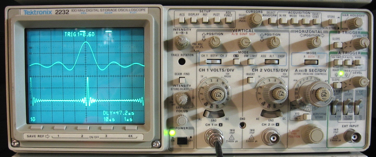
Tektronix 2232: 100 MHz Analog/Digital Oscilloscope. OK, after reading the Bonus Rant on the Tek 2230 right above this entry, you would think "why would he ever buy another one of these?" Well, the 2232 is better than the 2230, having a few more features that I will not go into. But the most important improvement was an increase in the digital sampling rate from 20 MHz to 100 MHz. And it was only $75. Note: it looks like the Tek repair people must have complained to the engineers, because the 2232 is a little better in terms of serviceability. In other words, you don't have to remove a bunch of pushbuttons just to be able to swing away the digital board to get to the rest of the guts. (PDF) Grade: A-
Advertised by the seller as not powering up and having some cosmetic flaws, his description was right on the mark. I prepared myself for a power supply fix, just like I had to do with the 2230, but a quick glance showed a missing fuse holder cap (and fuse). Luckily, I had the right cap on an old HP junker piece, and the 2232 fired right up. The "cosmetic flaws," however, were a bit more serious. The horizontal time base vernier shaft was bent and so I bent it back. The cursor pushbutton had no movement because the knob had been pushed onto the shaft too far. In fact, it was beginning to look like the front panel took quite a whack at some point in its life. The biggest damage was the channel two amplitude knob whose plastic camshaft had been sheared off. Fortunately some epoxy fixed that.
Postscript: My epoxy fix for the amplitude knob eventually failed. This time, I inserted some metal splines to hold the pieces together with some more glue. But I don't hold out much hope for the longevity of the fix. These knobs are used in many Tek 2200-series scopes, but they are pretty hard to find on their own. I did see one on eBay for $30 - a little pricey, especially when I could buy a malfunctioning Tek 2215A scope with two of these knobs for $50. So that's what I did. Plus, I got something else to fix!
Postscript^2: Preemptively replaced the two Rifa 0.0022 uF Y-capacitors with non-Rifa 0.0015 uF Y-capacitors in the power supply.
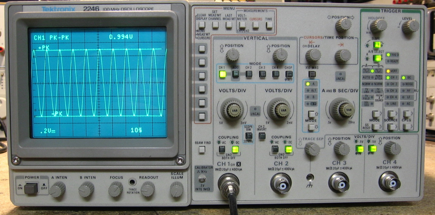
Tektronix 2246: 100 MHz, 4 channel analog oscilloscope. Well, it really is a "limited" 4-channel scope because channels #3 and #4 only have 0.1 and 0.5 V/div settings. In other words, Tek saved money by not having to include all the attenuators and fancy preamplifiers found in the normal channels #1 and #2. In fact, this scope was clearly designed to minimize cost (in the mid 1980s, Tek was worried about competitive test equipment imported from Asia). However, this cheapness actually makes the serviceability much better than my Tek 2230 and 2232. The knobology is a bit awkward since you have to push buttons repeatedly to scroll through the selections rather than using a simple lever switch. But you get used to it, and, in fact, this is probably the best 2200 series scope that I have ever used. The CRT traces and readout seem a cut above the other ones also in terms of brightness and clarity. I am very impressed with the 2246 and highly recommend it. (PDF) Grade: A
I was perusing eBay and saw a bunch of Tek 2246s for sale. In fact, one test equipment dealer had listed about 100 of these all at about $50 (+shipping) and all with one or more faults that were described in the listing. I went through all 100 listings and selected one that had no missing knobs and whose faults were most likely fixable. In this case, the one I liked was described as "channels #3 and #4 vertical positioning knobs not working (internal damage)". Looking at the schematic, these two knobs control pots whose resulting voltages go through an op amp and a 4053 demux chip. Since those two ICs were readily available, I purchased the unit. When received, I plugged it in and the scope went through its self-cal procedure indicating that the RAM backup battery had likely failed - no big deal. But then I selected channel #3 and turned the vertical position knob; it rotated freely as if nothing was hooked up to the knob. Same thing on channel #4. But then I tried all the knobs and all of them turned free with no resistance. I opened up the 2246 only to find that the entire potentiometer board was floating in the breeze and none of the knob shafts were connected! After I fixed that, the scope came alive and everything worked fine. The RAM backup batteries consist of two #391 silver oxide coin cells and they are famous for leaking. It was clear that someone had already cleaned up all the acid and corrosion on the processor board and installed new batteries (a few years ago probably). But the batteries only measured about 1/4 of their rated value, so I removed them and wired in a 3V Lithium 2/3-AA battery I had in the junkbox. I went through the complete calibration procedure and everything adjusted nicely. So the 2246 turned out to be a good buy at $50.
Postscript: Preemptively replaced the two Rifa 0.0022 uF Y-capacitors with non-Rifa 0.0015 uF Y-capacitors in the power supply.
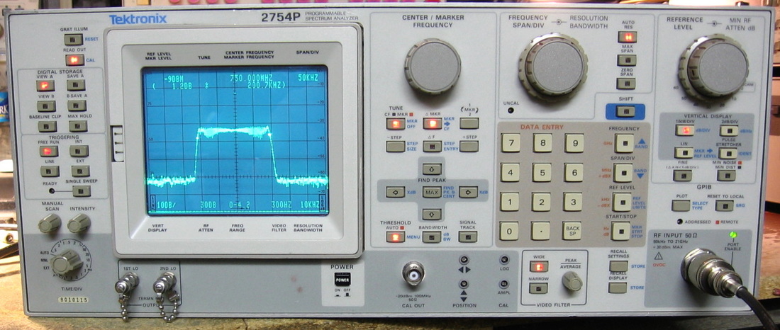
.
Tektronix 2754P: Microwave spectrum analyzer to 21 GHz. Several of my signal generators go in excess of 2 GHz and my Gigatronics 900 goes to 12.5 GHz, so my 1.5 GHz Rigol DSA-815 spectrum analyzer wasn't going to do the trick. What I thought was a bargain ultimately cost me a bundle (see the repair description below), but now I have gotten the microwave "bug" out of my system. The 2754P is basically the rack-mount version of the Tek 492/4 series and shares most of the same parts; the "P" means that it is programmable (via the back panel IEEE-488 interface). It is a curious mix of analog and digital in that the display has video memory. So the slow sweeps necessary for small resolution bandwidths that would normally require an analog storage scope (see the Tektronix 7633 below) present just fine on the 2754. In terms of specifications, it is mid-range (e.g., 1 kHz minimum RBW, phase noise at 1 GHz of -103 dBc/Hz @ 30 kHz offset, -88 to -110 dBm minimum average noise level (depending on frequency band) at 1 KHz RBW); Tektronix made a slightly better 2755 and lower frequency 2753 model. In terms of user interface, I don't think Tektronix did a very good job, and certainly nowhere near their customary oscilloscope man-machine interfaces. There aren't many menus, even though the thing is uP based, so there are a bunch of special purpose buttons as if the designer put only his odd combination of favorite functions on the front panel. In actual use, the display is not quite as crisp and stable as I would like, and the unit will drift slightly. I could try to properly adjust the piece. Let's see, about 60 pots and the customary, thoroughly abysmal Tektronix cal procedure - no thanks. (PDF) Grade: B+
Tektronix Spectrum Analyzer Bonus Rant! As I'm sure I've mentioned somewhere else on this webpage, the general theorem is: HP Equals Spectrum Analyzer and Tektronix Equals Oscilloscope. Certainly, nothing about the 2754P refutes that basic observation. But let me further explain myself... At work, I have a $90,000 Tektronix RSA-6000 and a $40,000 Tektronix WCA380 spectrum analyzer. Both have had very limited use and both have had hardware failures, requiring factory repairs of over $10,000 on each. Moreover, the man-machine interface and control software, particularly on the RSA-6000, is among the poorest I've ever seen, not only for spectrum analyzers, but for ANY piece of modern test equipment. Now I'm not saying that hardware failures are unique or even more likely with Tektronix equipment. But let's just say that the Agilent spectrum analyzers at work are the ones we all gravitate towards.
I paid $500 for this - the most I've ever spent on a used piece - which would be a pretty good deal had the thing worked. The seller offered no description other than it powered up. Upon receipt, the thing displayed no signal until I switched to a reference level that did not utilize the 20 dB pad in the step attenuator. And then, the displayed signal levels were still about 25 dB lower than expected. By disconnecting various pieces, I determined that the 1st mixer was also damaged. At that point, I asked the seller to either accept the unit back, or to refund me $250 to help me pay for the repairs. He chose the latter option and so now I started the repair. I located a replacement 1st mixer, but needed to pay $290 for it. So right off the bat, I'm over budget. After receiving the new mixer, the levels were still 25 dB down and the problem was traced to the DC Bias Return module which supplies bias to the mixer diodes. A new ($30) module fixed that and the levels snapped back to where they should have been. That left me with the step attenuator which consists of 10, 20 and 30 dB pads. Unfortunately, the 20 dB was toast (open) and the pads are pretty much unobtainable now (they used to be relatively easy to get). My solution was to use an HP 33322 attenuator (10, 20, 40, 40 dB pads to 18 GHz) and build an interface circuit that was published on-line by OH2GAQ. The first HP 33322 I received tested bad, so I got a refund and bought another. That one also tested bad, but at least one of the 40 dB pads tested out at 20 dB. So as a stop-gap, while I'm waiting to get a refund/exchange on the second bad HP 33322, I wired up a simple 2-transistor interface circuit to control the 40 dB pad (20 dB) and ran the HP 33322 in series with the Tek attenuator with its 20 dB pad bypassed. Problem temporarily solved. Bottom line: I ended up spending about $700 for the 2754P. It's still comfortably below what they usually go for on eBay, but ouch! I think this piece will end my excursion into microwave. The parts are just too hard to come by and it is a lot more difficult to substitute circuitry than at lower frequencies.
Postscript: I finally did the interface circuit mentioned above. See photo below. I pulled out the broken Tektronix attenuator and put the interface board in its place. I found a suitable location along a side rail for a (finally) working NOS Weinschel 150 18 GHz 110 dB step attenuator that I bought cheap and reworked the front panel input hardline to meet its input. A new piece of hardline connects the attenuator output to the input of the mixer. Should last forever (famous last words!).
Postscript^2: One of the red LEDs illuminating a front panel button burned out. Easy fix.
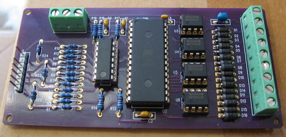
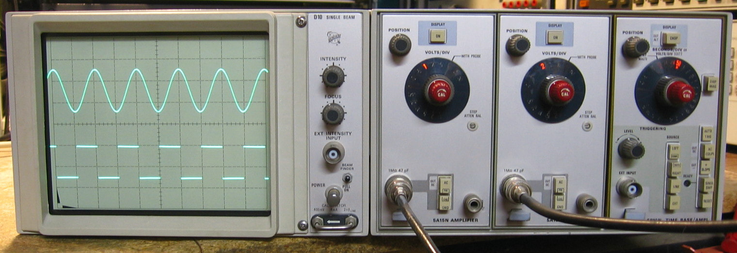
Tektronix 5110: Low frequency (2 MHz) oscilloscope with two 5A15N (vertical) and 5B10N (horizontal) plug-ins. Here's where it gets confusing. Tektronix first sold these things (in the early 1970s) with a modular approach. One chassis contained the power supply and the three slots for the plug-ins. The other chassis contained the CRT and associated driver circuitry. The two chassis could be mated either side-by-side or on top of one another. The idea was that one could select from a variety of single, dual, non-storage or storage displays; Tek sold about eight different ones. Mine is the least capable D10 model. Tek originally branded my scope as a 5103/D10, but confusion soon reigned and they relabeled all of the 5103/Dnn models simply to 51nn. It gets even more confusing because they later came out with the higher bandwidth 5400 series. Now, none of the 5100-series plug-ins should be confused with the plug-ins for the TM500 or TM5000 chassis - they might be the same physical size, but they are completely incompatible. I assume these low bandwidth scopes were marketed to people needing instrumentation for low frequency sensors, such as geological transducers, or perhaps for audio applications. They are, of course, pretty useless in a general lab situation. But the lack of high frequency response actually could be a blessing in certain situations in terms of noise reduction. In fact, at 1 mV/div, the trace is much cleaner than my more modern "better" scopes. The CRT is an 8×10 division screen where each division is 0.5 in instead of the standard 1 cm per division. Simple to operate and unlike the vast majority of Tektronix scopes, simple to service with hardly any custom ICs. (PDF) Grade: B+
I specifically bought this because the eBay photo showed the trace completely screwed up with all kinds of echos and retraces. At least I hoped to get several hours of entertainment out of it. When received, the traces were even worse than shown in the photo and virtually none of the controls functioned correctly. It was so screwed up that I surmised the problem had to be improper power supply voltages. And so it was, as I found the 30 V rail oscillating at 120 Hz between 12 V and 30 V. After replacing the obviously faulty main electrolytic cap, things started to look reasonable. This scope is >45 years old and you can imagine how dirty all the switches were, so the plug-ins were removed and cleaned (a few times). Going through the alignment, I noticed that the trace rotation potentiometer had no effect (and the trace was annoyingly tilted about 5 degrees). The pot has 30 V and -30 V across it and the wiper sends the selected voltage through the trace rotation coil surrounding the CRT and then to ground. The wiper of the pot was producing the correct voltage, so I pulled the wire off of the pot going to the coil and found that the coil was open. No wonder I did not get any trace rotation. At this point, I figured I had nothing to lose so I removed the CRT and yanked out the trace rotation coil. Dissecting my way through all of the insulation surrounding it, I soon found the open solder joint connecting the coil lead to the wire going to the pot. Soldered it, reinstalled everything, and now my trace can be rotated. I'm kind of glad I did this surgery because when I removed the main connector from the CRT, I found three bent pins (courtesy of a previous incompetent repairman). I'm amazed that they actually were making contact. The only other fault I found was a burned out bulb in the "ready" indicator on the 5B10N for single sweep. Replacing that was even harder than my rotation coil fix.
Postscript: Further experimentation revealed that the channel #1 5A15N plug-in was intermittent with a baseline that would shift around randomly. I tested the transistors in-circuit and found one (2N4249) that did not test correctly. I pulled it and threw it on my Peak Component Analyzer which concluded it was a Darlington with a 1.4 volt B-E drop. That's strange, because it isn't supposed to be a Darlington. I popped another one out just to be sure and the second transistor tested fine with the expected 0.7 V drop. I didn't have a 2N4249, so I threw in a 2N4403 which isn't a "low noise" transistor like the 2N4249. But it seems to have fixed the problem with no increase in noise at the 1 mV/div setting that I can see.
Postcript^2: I have noticed that Channel #1 exhibits the behavior that the trigger level knob will only trigger an input if it is set just right - with about 5 degrees of slop. Channel #2, on the other hand, will trigger with about 30 degrees of movement of the level knob. I replaced the three 2N3565 transistors making up the trigger pickoff circuit in Channel #1 with 2N3904s and now it behaves correctly. A forensic analysis showed that one of the 2N3565 had severely reduced beta.
Tektronix Scope Collection Bonus Rant! With this latest acquisition, I now have Tektronix oscilloscopes from the 200, 300, 400, 2000, 5000, 7000, T900 and TDS series! That pretty much does it unless I am interested in the early vacuum tube models (I'm not) or want to spend thousands on a post-2000 manufactured model (I don't). But I think it does qualify me to enter an opinion. I have said it several times already on this web page - Tektronix really does know how to make an oscilloscope. Sure, I have complained in other Bonus Rants about their needlessly complicated mechanical designs, cam switches and difficult disassembly procedures, but some of that is most likely related to Tek's attempt to lower manufacturing costs (at the expense of future serviceability). But I find their CRTs superior to others in terms of clarity and I find their mostly consistent knobology (particularly in the later TDS models) also to be the best. If you have your mind set on a 1970 - 1995 vintage oscilloscope, get a Tektronix model. Don't waste your money on other brands.

Tektronix 7603 (Horiz): Has the 7D20 digitizer which can store 6 waveforms, compute envelopes, averages, etc. Also switches to a strip chart at large time/divs. Extremely useful for low frequencies. The Tek 7600 scopes are a pleasure to use and have nice big CRTs. ($CD) Grade: A-
Scope worked fine. The problem was with the plug-ins. See the discussions below.
Scope worked fine. The problem was with the plug-ins. See the discussions below.
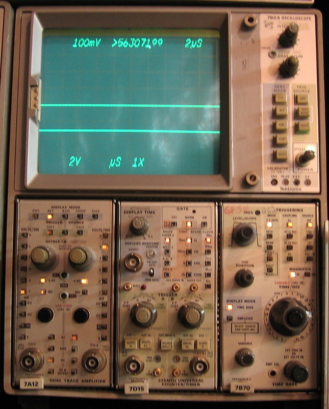
Tektronix 7603 (Vert): Basic 100 MHz scope configured with a 7A12 vertical amp, a 225 MHz 7D15 counter and a 2ns/div 7B70 time base. (PDF) Grade: B+
Scope worked fine. The problem was with the plug-ins. See the discussions below.
Scope worked fine. The problem was with the plug-ins. See the discussions below.
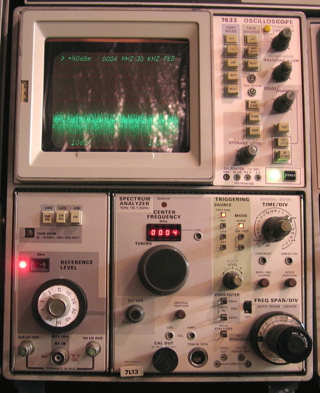
Tektronix 7633: This is a full storage scope that is configured as a 1.8 GHz spectrum analyzer with the 7L13 plug-in. The plug-in is just about the most complicated thing Tek ever produced. You have to have the knack to properly use a storage scope. The display tends to bloom very easily. (PDF) Grade: B-
I bought this storage scope specifically to use with the 7L13 spectrum analyzer. The storage feature allows one to see the spectrum with a slow sweep. The scope worked fine. The 7L13 did not. I had to replace the inner shaft and rebuild the inner mechanism of the attenuator - very difficult and took a few tries. There was also one filter relay in the IF chain that I had to replace. Tektronix at one point designed and built their own relays. There is nothing available with a pinout remotely like them anywhere. So the replacement was mounted upside down and wires run back to the board in the proper order.
I bought this storage scope specifically to use with the 7L13 spectrum analyzer. The storage feature allows one to see the spectrum with a slow sweep. The scope worked fine. The 7L13 did not. I had to replace the inner shaft and rebuild the inner mechanism of the attenuator - very difficult and took a few tries. There was also one filter relay in the IF chain that I had to replace. Tektronix at one point designed and built their own relays. There is nothing available with a pinout remotely like them anywhere. So the replacement was mounted upside down and wires run back to the board in the proper order.

Tektronix 7904: Rated to 500 MHz, but will easily do 700 MHz. Has the 200 MHz 7A24 vertical amp, the 600 MHz 7A19 vertical amp and two 7B80 series 1ns time bases. This and the Fluke 3390B are the two scopes I rely upon. Excessively large size in my opinion. Must have been a marketing ploy by Tek: size = quality. ($CD) Grade: A-
Postscript: Well, times have changed and the 7904 and Fluke 3390B are no longer "the two scopes I rely upon." Other than looking at modulated RF signals, the newer digital scopes (like my HP 54522A) are now my "go-to" scopes.
I took a chance on this one. Advertised as "no display." But it was such a nice scope, I figured I would risk it. Opened it up, reattached the HV wire to the tube, now it is "display," not "no display." And that's the way, uh huh, uh huh, I like it, I like it.
Postscript: Turned it on one day and the CRT wouldn't stay in focus. To make a long story short, the front panel focus knob is only part of the adjustment; there is also a "pre-focus" potentiometer on the z-axis board inside. That pre-focus pot had gone bad and was suitably replaced with one from the junkbox.
Postscript^2: One day, the 7B85 timebase unit was acting flaky. The problem was traced to an 800K resistor used to set the RC time constant and was suitably replaced (the resistor opened up affecting the accuracy of most of the timebase settings).
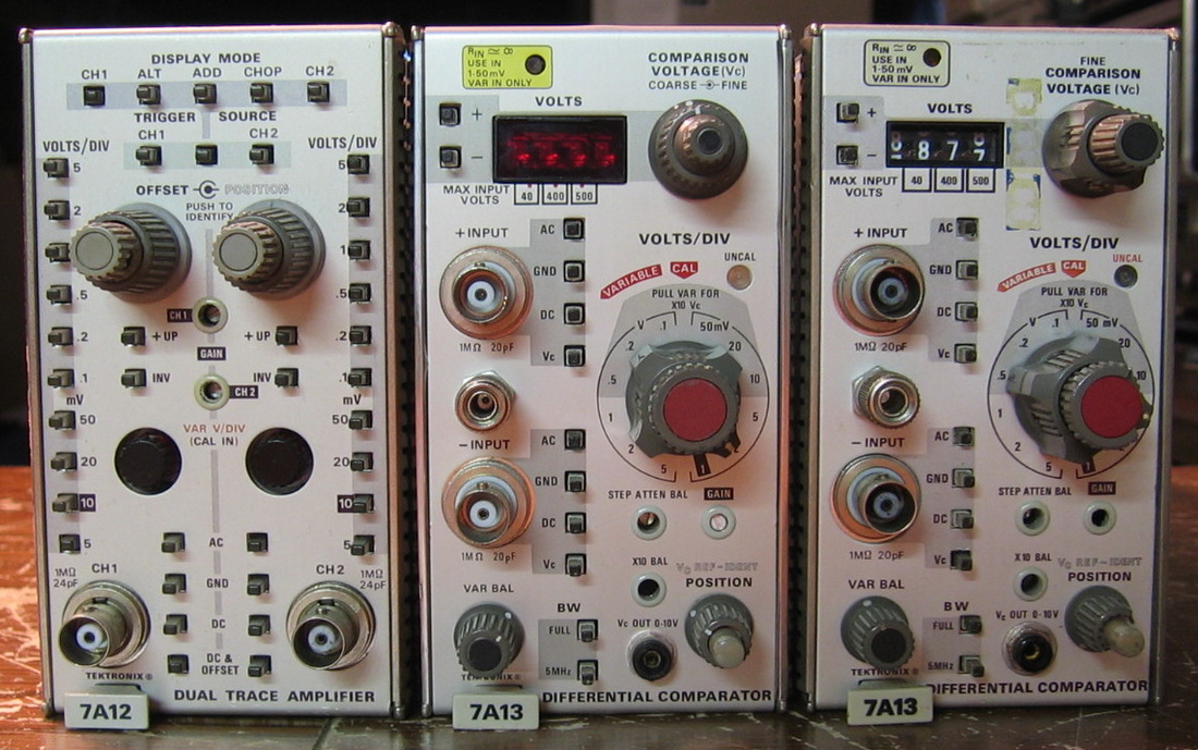
Tektronix 7A12, 7A13 (new & old): Various Tektronix vertical amplifier plug-ins for the 7000 series. Can't have a bunch of 7000 series scopes without a bunch of 7000 series plug-ins. I think I have about two dozen in total. All are a maintenance nightmare courtesy of the Tektronix mechanical designers who should have all been committed to mental institutions years ago. ($CD) Grade: B
Rather than describe all the fixes, I'll summarize. The same comments apply for the other Tek plug-ins listed on the page. Very simply: Tektronix problems = mechanical, HP problems = electrical. I've learned this theorem over several years. Part of Tek's problem was their propensity to socket everything, including transistors. Then there's the cam switches. You can fix 90% of the 7000-series plug-ins by reseating everything in a socket and disassembling and cleaning the cam switches. The remaining 10% are switches, pots, tantalums, light bulbs, etc.
Rather than describe all the fixes, I'll summarize. The same comments apply for the other Tek plug-ins listed on the page. Very simply: Tektronix problems = mechanical, HP problems = electrical. I've learned this theorem over several years. Part of Tek's problem was their propensity to socket everything, including transistors. Then there's the cam switches. You can fix 90% of the 7000-series plug-ins by reseating everything in a socket and disassembling and cleaning the cam switches. The remaining 10% are switches, pots, tantalums, light bulbs, etc.
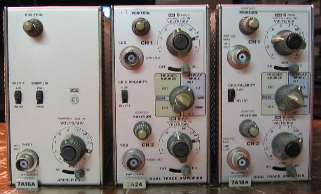
Tektronix 7A16A, 7A18A, 7A24: Various Tektronix vertical amplifier plug-ins for the 7000 series. ($CD) Grade: B
See the comments for the Tektronix 7A12, 7A13.
See the comments for the Tektronix 7A12, 7A13.
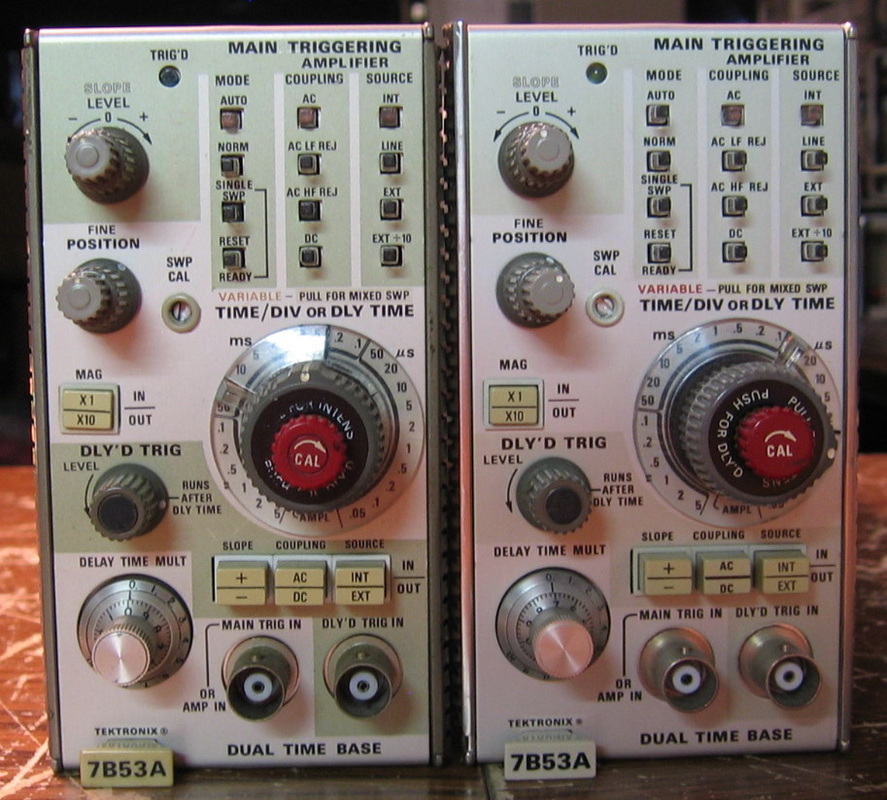
Tektronix 7B53A: The "canonical" time bases that do all of the intensity, delay functions. (OM) Grade: B
See the comments for the Tektronix 7A12, 7A13.
See the comments for the Tektronix 7A12, 7A13.
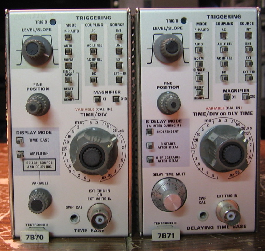
Tektronix 7B70, 7B71: Some more 7B70 series time bases. These were among the few that used Tunnel diodes. When they go, throw the whole thing in the garbage. ($CD) Grade: B
See the comments for the Tektronix 7A12, 7A13.
See the comments for the Tektronix 7A12, 7A13.
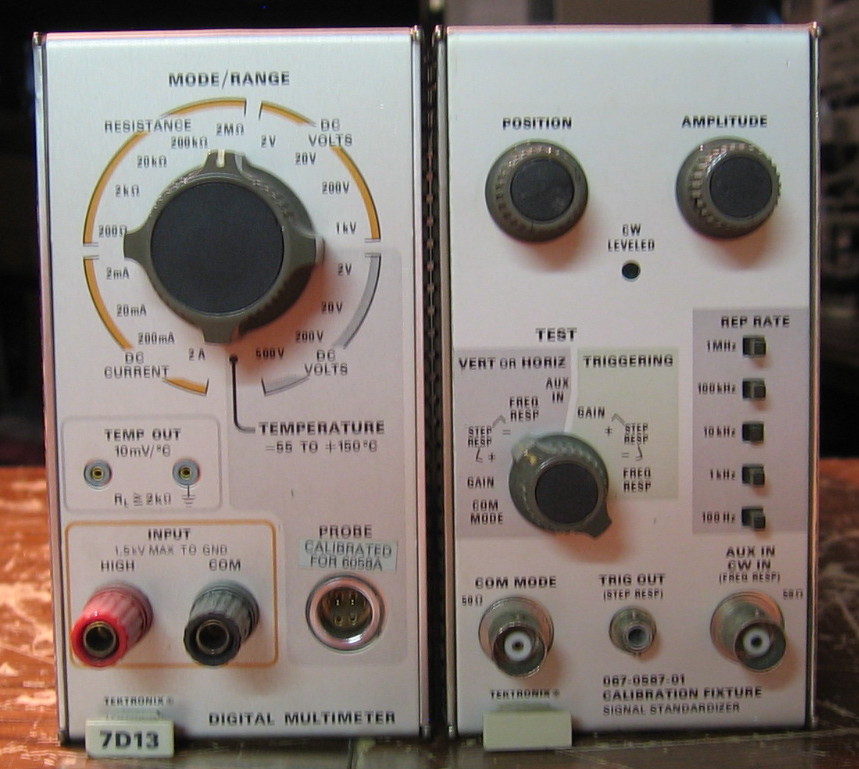
Tektronix 7D13, Calibrator: Miscellaneous Tek plug-ins; a DMM and a Calibrator. ($CD) Grade: B
See the comments for the Tektronix 7A12, 7A13.
See the comments for the Tektronix 7A12, 7A13.
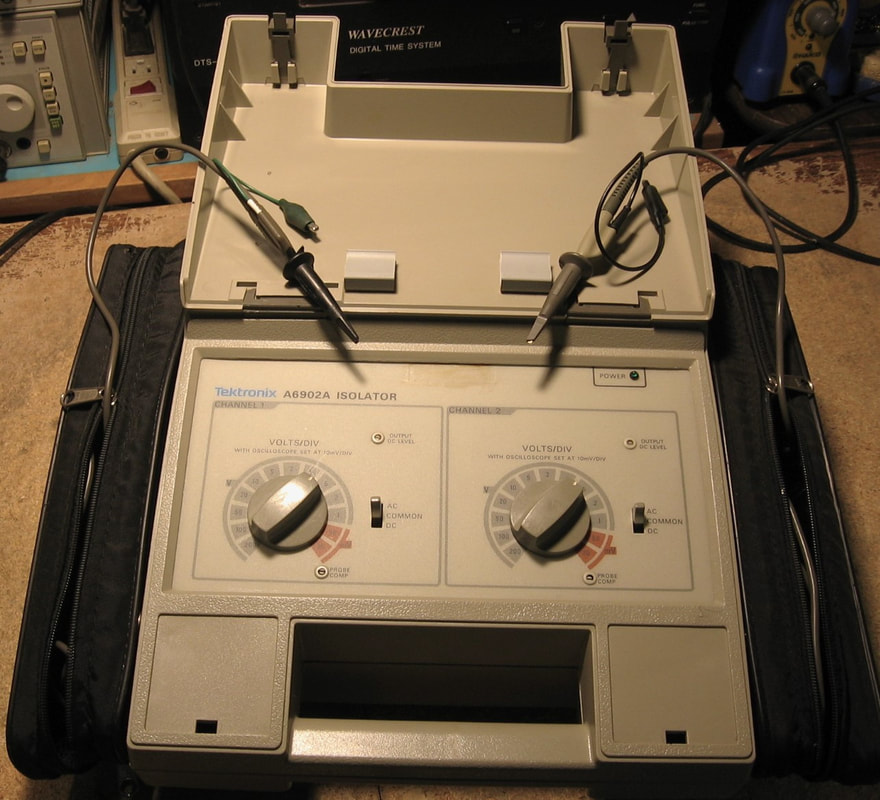
Tektronix A6902A: Probe Isolator. The Tektronix A6902A is a two-channel probe and isolator for use with standard oscilloscopes. Almost all standard oscilloscopes have their grounds at earth potential. This can get you into a lot of trouble if, for instance, you are trying to scope the primary of a switching power supply and hook up your scope probe ground to the circuit common of the primary (which you would normally do with most things you are probing) since that is usually something like -170 VDC. Poof goes your scope, the unit under test, or perhaps you! With the A6902A, you get two 500 volt, 20 MHz probes that are completely isolated from earth ground. You can hook up an A6902A probe ground lead pretty much wherever you want (although the manual suggests a low impedance path) and be assured that the output, which goes to your oscilloscope set to 10 mV/div, is completely safe. Note: you can also safely work on dangerous things with your normal scope probes by doing a differential measurement using two probes, but the A6902A is a little more convenient (and safer) and has two totally separate channels (isolated from earth ground and isolated from each other). The A6902A is simple to operate and only has controls for V/div, coupling, DC centering and probe compensation. The only downside to the unit is the size - it is huge, probably larger than the unit you are testing and your oscilloscope. (PDF) Grade: B+
Advertised by the seller as condition unknown, the pictures showed the ground lead was missing from one of the two included probes. That was easily remedied from my junkbox. The coupling switch on channel 2 did not work, but I dissected the unit and flushed the switch with contactor cleaner which fixed the problem. While I was in there, I noticed that one of the strain reliefs for the probe cable had snapped off and so that was expoxied back. The problem with the A6902A is that Tektronix made three versions over the years, the A6902, A6902A and A6902B. Unfortunately the three versions have different circuit boards. While the service manuals for the A6902 and the A6902B are freely available on the web, the A6902A manual is nowhere to be found. Or so I thought, because a few days later I stumbled across a forum post from another A6902A owner looking for the manual with a subsequent reply that suggested he contact vintagetek.org. So I figured it was worth a shot and I contacted vintagetek.org. A few hours later and I had the manual! So go and check out the vintagetek.org webpage. Calibrating the A6902A is akin to calibrating Tek 400 or 7000 series oscilloscope front-ends, namely a lot of resistors and capacitors to adjust the gains, DC offsets and step responses. And like the Tek scopes, one can never get everything adjusted perfectly because there is so much interaction among the settings.
Advertised by the seller as condition unknown, the pictures showed the ground lead was missing from one of the two included probes. That was easily remedied from my junkbox. The coupling switch on channel 2 did not work, but I dissected the unit and flushed the switch with contactor cleaner which fixed the problem. While I was in there, I noticed that one of the strain reliefs for the probe cable had snapped off and so that was expoxied back. The problem with the A6902A is that Tektronix made three versions over the years, the A6902, A6902A and A6902B. Unfortunately the three versions have different circuit boards. While the service manuals for the A6902 and the A6902B are freely available on the web, the A6902A manual is nowhere to be found. Or so I thought, because a few days later I stumbled across a forum post from another A6902A owner looking for the manual with a subsequent reply that suggested he contact vintagetek.org. So I figured it was worth a shot and I contacted vintagetek.org. A few hours later and I had the manual! So go and check out the vintagetek.org webpage. Calibrating the A6902A is akin to calibrating Tek 400 or 7000 series oscilloscope front-ends, namely a lot of resistors and capacitors to adjust the gains, DC offsets and step responses. And like the Tek scopes, one can never get everything adjusted perfectly because there is so much interaction among the settings.
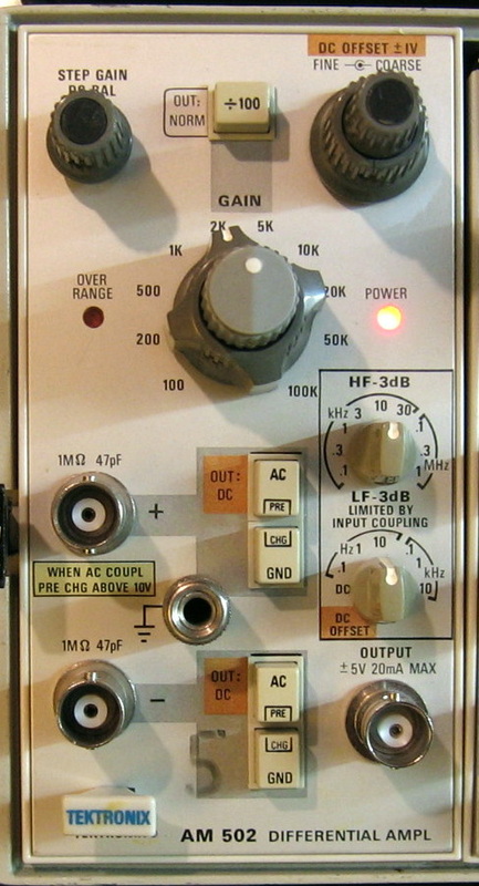
Tektronix AM502: Like the manual says, "The AM502 is a DC-coupled differential amplifier with excellent common-mode rejection capabilities and high gain for low voltage measurements." For use with the TM-5xx mainframes. (PDF) Grade: B
I originally used this for spare parts to fix mechanical things in the other Tek 500 series plug-ins (see below). But then I figured what the hell - some metal scraps, a Dremel tool, epoxy... Good as new.
I originally used this for spare parts to fix mechanical things in the other Tek 500 series plug-ins (see below). But then I figured what the hell - some metal scraps, a Dremel tool, epoxy... Good as new.

Tektronix DC503 (in TM503 mainframe): Your basic 100 MHz counter for the 500-series mainframe. The front panel is a bit confusing, but the thing counts as advertised. (PDF) Grade: B-
This unit was unresponsive when received. There is an overvoltage protection circuit inside whose SCR had fired and blew an internal fuse. I replaced the fuse but the unit's P/S still was not producing correct voltages. I put it aside for a couple of days while I fixed the Tektronix FG501 and FG502. When I plugged the DC503 back in, it worked fine. Must be magic or something (maybe the SCR finally let go). The big problem with this unit was that it was all smashed up. I straightened it out as best I could and also manufactured a new red plastic window for the display.
This unit was unresponsive when received. There is an overvoltage protection circuit inside whose SCR had fired and blew an internal fuse. I replaced the fuse but the unit's P/S still was not producing correct voltages. I put it aside for a couple of days while I fixed the Tektronix FG501 and FG502. When I plugged the DC503 back in, it worked fine. Must be magic or something (maybe the SCR finally let go). The big problem with this unit was that it was all smashed up. I straightened it out as best I could and also manufactured a new red plastic window for the display.
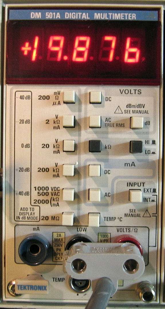
Tektronix DM501A: 4-1/2 digit digital multimeter for a TM500x chassis. The DM501A Multimeter Module measures DC voltage from 200 mV to 1000 V in 5 ranges. True RMS AC voltage ranges from 200 mV to 500 V. Resistance from 200-ohms to 20 Mohms in 6 ranges. DC and True RMS AC current 200 µA to 2000 mA in 5 ranges. Best case DC accuracy is 0.05%. The other functions are substantially worse. I've had this piece for many years, but recently discovered that I never posted it to this web page. (PDF) Grade: B
This unit had many stuck bottons and an open electrolytic capacitor in the 15 volt power supply.
This unit had many stuck bottons and an open electrolytic capacitor in the 15 volt power supply.
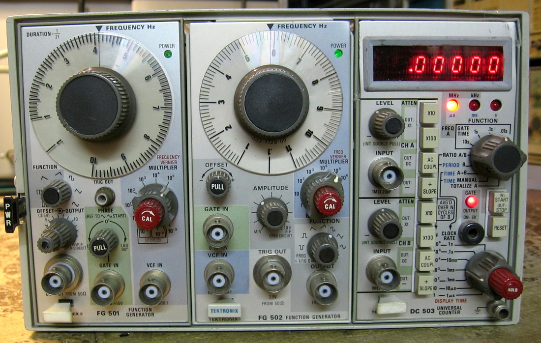
Tektronix FG501, FG502 (in TM503 mainframe): These two units are 500-series plug-ins for the TM503 mainframe. The FG501 goes to 1 MHz and the FG502 goes to 11 MHz. There are the usual sine, triangle, pulse and ramp functions. The idea is to use the FG501 output as an input to either the gate or the Voltage Controlled Frequency input of the FG502 for more complex waveforms. Tektronix updated the FG501 to an FG501A and it's easy to see why - the switching speed for the triangle generator is about 200 nsec. Makes for an awfully distorted waveform at the upper frequency ranges. (PDF) Grade: B-
The FG501 was completely dead when received. After finding two defective 741 op-amps in its P/S and another defective 741 op-amp in the triangle generator, I decided to simply replace all thirteen 741s. I also reattached the wires going to the main tuning pot as well as did some general mechanical fixes (knobs, shaft couplers).
The FG502 was also completely dead when received. I learned my lesson from the FG501 and replaced all nine 741s. And wouldn't you know that one of the "new" 741s was also defective! The wires from its tuning pot were also disconnected (must be contagious) and a resistor in the output circuit had cracked in half. But after all these fixes, the thing was terribly screwed up. Seems as though someone had given the frequency range selector knob a real good whack. That pushed in the shaft and actually moved the 13 position cam switch one position over; all thirteen switches on the cam were being switched incorrectly. I managed to fix all of that without breaking any of the contacts (those of you who have worked on Tek 7000 series stuff know the drill).
Postscript: Years later, the FG502 let out its magic smoke. This was traced to a faulty 10 uF tantalum bypass capacitor on the 20V line feeding the collector of the output transistor through a 10 ohm resistor (the resistor was the smoker). After replacing the cap and the resistor, the unit powered up fine but the DC offset didn't work. I inadvertently knocked off one of the wires going to the offset potentiometer when I was replacing the 10 ohm resistor. After that was repaired, the DC offset still didn't work. Turns out I knocked TWO wires off of the pot. All is well now.
Postscript^2: Call it karma, but the 10 uF tantalum on the -20V line blew shortly after I fixed the one on the +20V line.
Postscript^3: The FG502 developed a zero-baseline jitter which was traced to an unsalvageable dirty pot which was then simply replaced.
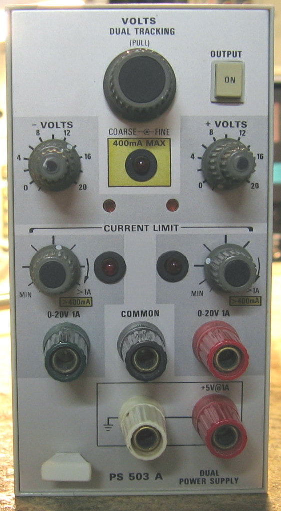
Tektronix PS503A: Triple output power supply plug-in for my TM5006 mainframe. Will do a fixed 5V @ 1A and dual 20V @ 1A. This is one of Tek's better attempts since it has full current limiting controls plus a nifty tracking potentiometer that will adjust both 20V supplies to a proportion of their settings. (PDF) Grade: A-
Nothing to do but replace one of the internal fuses and spritz the switches.
Nothing to do but replace one of the internal fuses and spritz the switches.
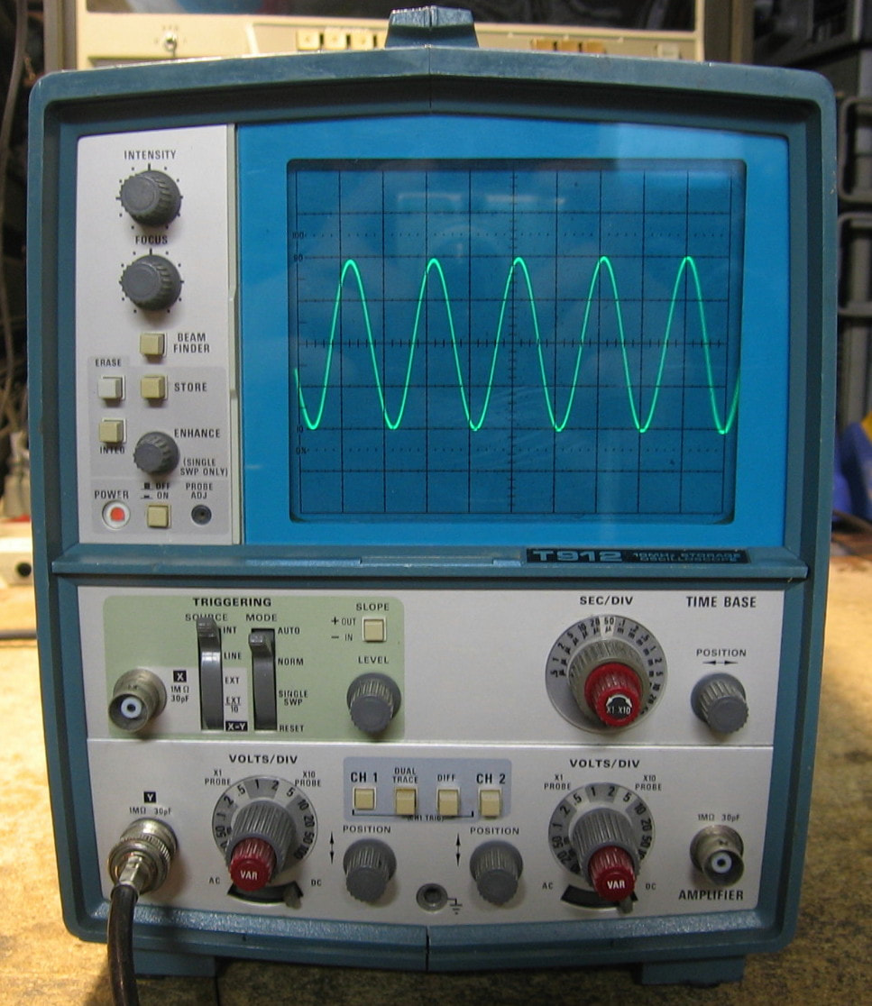
Tektronix T912: Two channel, 10 MHz storage oscilloscope from the 1970s. Pretty useless nowadays except possibly to repair some vintage audio equipment or to teach a high school student how to use a scope. Does not use any custom Tek semiconductors, so is relatively easy to fix. Moreover, unlike most other Tek mechanical designs, this one seems well thought out and is a snap to disassemble (once you've read the manual). A bare bones piece but implemented very well for what it is. ($CD) Grade: B+
The T912 was received in the advertised condition: fan runs when powered on, no other activity seen. A check of the internal fuse on the (unregulated) 120 VDC power supply output showed it blown. Moreover, an inspection of the P/S board revealed an electrolytic cap with a broken solder joint and a shorted diode nearby. After the fuse, cap and diode were replaced, the scope powered up fine but not all the P/S voltages were correct. Indeed, the regulated 120 VDC was about 12 V; the unregulated 120 V was fine. Rather than separating the P/S from the rest of the circuitry (I figured out an easy way to do this eventually), I removed the transistor in the 120 V regulator circuit responsible for foldbacking the supply in the event of over-current. That immediately let the smoke out on the board driving the CRT. One of the 120 V lines goes through a 470 ohm resistor into one of the CRT grids with a 0.033 uF cap to ground. The cap had shorted and now I had full current through the 470 ohm resistor - poof! Once the cap and burned resistor were replaced, all my P/S voltages were correct and the scope appeared to work. Shortly thereafter, however, the trace went to full brightness with little change from the intensity knob and was unable to focus sharply. Also, on certain time bases it looked like the scope was drawing a second waveform on top of the first one with about 1/10th the sweep time. And at low time bases (>1 msec), I was only getting about 1/4 of the horizontal waveform and the retrace time seemed way too long. This all pointed to something to do with the blanking circuit, but it wasn't clear what the intensity and/or focus problems had to do with the blanking. While I was trying to diagnose, the scope abruptly started to work flawlessly. Over the next few days, sometimes it would work and sometimes it would go into the weird behavior. When it did change and I happened to be watching, the change was instantaneous. Finally, the CRT went totally dark. The HV (~ -2700V) for the CRT cathode and grid are developed off two secondaries of a switching power supply transformer each having a 10 KV, 10 ma diode. When I tested these with my DMM, they were open. This led me on a wild goose chase debugging the HV circuit until I stumbled on a repair forum describing how to test these HV diodes. [Lesson #1: HV diodes are internally comprised of several lower voltage diodes in series. Hence, your normal DMM (either ohms or diode function) doesn't have enough output voltage to get the diode to conduct - they will read open in both directions]. So I hooked up my HP 6177C current source with a 50 V compliance and successfully pumped a few mA through the two diodes (with no current in the reverse direction) which proved the HV diodes were indeed OK. So back to the original problem - the unblanking signal. This signal actually is summed in with the intensity control voltage which explains why a malfunction in the unblanking could also effect the trace brightness. The unblanking signal is developed via two 7400 quad-nand chips on the horizontal board, so I pulled them both out and one tested bad. Socketed the two ICs, put the good one back and a new one for the bad chip. That seemed to fix my problems until I noticed that now the auto and normal triggers don't work correctly. [Lesson #2: When you desolder an IC, then socket the board, don't put the old IC back. It may not make good contact in the socket. Either put a new IC in the socket, or directly solder the old IC back in the board]. After I removed the sockets and soldered the chips back in the board, everything was fixed. Or was it? Now the vertical baseline on channel #1 was moving all over the place with the V/div knob. All my jostling around with the boards must have loosened some of the pins that are used as board interconnects, because there is one particular screw that helps hold the vertical board in which cured the vertical baseline problem as soon as I loosened it a half a turn! I simply left the screw out rather than putz around with it any more.
The T912 was received in the advertised condition: fan runs when powered on, no other activity seen. A check of the internal fuse on the (unregulated) 120 VDC power supply output showed it blown. Moreover, an inspection of the P/S board revealed an electrolytic cap with a broken solder joint and a shorted diode nearby. After the fuse, cap and diode were replaced, the scope powered up fine but not all the P/S voltages were correct. Indeed, the regulated 120 VDC was about 12 V; the unregulated 120 V was fine. Rather than separating the P/S from the rest of the circuitry (I figured out an easy way to do this eventually), I removed the transistor in the 120 V regulator circuit responsible for foldbacking the supply in the event of over-current. That immediately let the smoke out on the board driving the CRT. One of the 120 V lines goes through a 470 ohm resistor into one of the CRT grids with a 0.033 uF cap to ground. The cap had shorted and now I had full current through the 470 ohm resistor - poof! Once the cap and burned resistor were replaced, all my P/S voltages were correct and the scope appeared to work. Shortly thereafter, however, the trace went to full brightness with little change from the intensity knob and was unable to focus sharply. Also, on certain time bases it looked like the scope was drawing a second waveform on top of the first one with about 1/10th the sweep time. And at low time bases (>1 msec), I was only getting about 1/4 of the horizontal waveform and the retrace time seemed way too long. This all pointed to something to do with the blanking circuit, but it wasn't clear what the intensity and/or focus problems had to do with the blanking. While I was trying to diagnose, the scope abruptly started to work flawlessly. Over the next few days, sometimes it would work and sometimes it would go into the weird behavior. When it did change and I happened to be watching, the change was instantaneous. Finally, the CRT went totally dark. The HV (~ -2700V) for the CRT cathode and grid are developed off two secondaries of a switching power supply transformer each having a 10 KV, 10 ma diode. When I tested these with my DMM, they were open. This led me on a wild goose chase debugging the HV circuit until I stumbled on a repair forum describing how to test these HV diodes. [Lesson #1: HV diodes are internally comprised of several lower voltage diodes in series. Hence, your normal DMM (either ohms or diode function) doesn't have enough output voltage to get the diode to conduct - they will read open in both directions]. So I hooked up my HP 6177C current source with a 50 V compliance and successfully pumped a few mA through the two diodes (with no current in the reverse direction) which proved the HV diodes were indeed OK. So back to the original problem - the unblanking signal. This signal actually is summed in with the intensity control voltage which explains why a malfunction in the unblanking could also effect the trace brightness. The unblanking signal is developed via two 7400 quad-nand chips on the horizontal board, so I pulled them both out and one tested bad. Socketed the two ICs, put the good one back and a new one for the bad chip. That seemed to fix my problems until I noticed that now the auto and normal triggers don't work correctly. [Lesson #2: When you desolder an IC, then socket the board, don't put the old IC back. It may not make good contact in the socket. Either put a new IC in the socket, or directly solder the old IC back in the board]. After I removed the sockets and soldered the chips back in the board, everything was fixed. Or was it? Now the vertical baseline on channel #1 was moving all over the place with the V/div knob. All my jostling around with the boards must have loosened some of the pins that are used as board interconnects, because there is one particular screw that helps hold the vertical board in which cured the vertical baseline problem as soon as I loosened it a half a turn! I simply left the screw out rather than putz around with it any more.
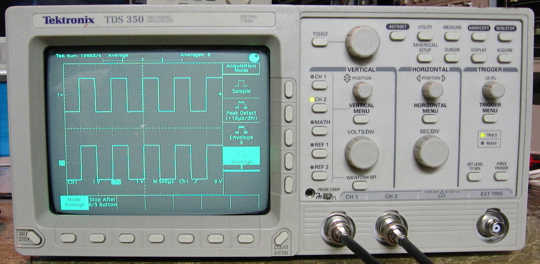
Tektronix TDS350: Two channel, 200 MHz digital scope from the mid-1990s. Although the nameplate says 1 Gs/s sampling, Tektronix cheated a bit. Sure, the analog voltages are "stored" at that rate into an analog ASIC. Then they are digitized into memory at 25 MHz. While this preserves the 1 GHz effective rate and no information is lost, the impact is, of course, a much slower waveform update rate than one would truly get at full speed. Since the anti-alias pre-sample filter Tek used has a rather shallow roll-off, the 1 GHz sampling should support waveforms up to 500 MHz. And so it does - the scope has no problems at all triggering and capturing a 450 MHz sine wave (albeit at a lower amplitude). Tek made a slew of related scopes in this era, the TDS 400, 500, 600, 700 and 800 series, each getting progressively better (and more expensive). Mine is the upper end of the TDS300 series (TDS310 at 60 MHz, TDS320 at 100 MHz and TDS350 at 200 MHz). They only lasted a couple of years until Tek came out with the TDS340, 360 and 380. The TDS series all share the fantastic basic front panel buttonology which pretty much has been maintained to the present day. Minimal interaction and everything is to the point. I'm usually critical of Tektronix equipment (particularly their 1970's and 1980's stuff) because of their excessively complex mechanical designs. But I do have to admit: Tektronix really does know how to make an oscilloscope. And I find the clarity of the CRT superior to the HP scopes of that era. (PDF) Grade: A
I spent a fair amount on this piece: $150 + shipping. Usually I don't, but even broken TDS350s go for $300 to $500 routinely. Mine was advertised as condition unknown and the listing photo showed the boot-up screen with a "Cal Initialization Failure." My guess was that the NVRAM (a Dallas 256K RAM with an integrated, non-replaceable 10 year battery) was toast and that the thing simply lost its cal constants. Turns out the NVRAM, dated 1995, wasn't toast. But I dutifully replaced it with a 2013 date code NVRAM and ran the cal procedures only to find that they failed. The scope seemed to work somewhat on channel #1, but without the cal constants in my new NVRAM, the baseline (ground) was all over the place and the trigger levels were also way off. Channel #2 worked similarly, but the trace vanished off the screen at <50 mV/div settings and no controls would bring it back. Since the cal constants are written into NVRAM if and only if the entire (two channel) cal procedure succeeds, I was in a world of hurt. Taking a break, I turned my attention to the CRT whose display was rotated about 20 degrees. There was no pot to adjust, but the yoke was simply loose and needed to be rotated back and hot melt glued into position. While pondering my broken channel situation, I hooked an ohmmeter up to the two BNC jacks. Channel #1 measured 1M as expected, but channel #2 was about 600K. Very curious indeed until I switched the DMM from ohms to volts only to find that there was 7 VDC emanating from channel #2's BNC jack. Even more curious, because the schematics showed that the input hybrid preamp circuit's Vcc was 5 VDC. However, as soon as I put any kind of load (several hundred Kohms) on the BNC jack, the 7 volts dropped way down towards zero. So my conclusion was that the input preamp hybrid was bad. Now, the TDS350 consists of a switching P/S, a display board, front panel board, a CRT and a mainboard. The mainboard is the size of a small paperback book and basically contains the entire scope. There are two 45-pin daughterboards for the two input preamps that plug into this mainboard. The mainboard and daughterboards are all custom Tek hybrid designs with lots of surface mount ASICs. Anyway, returning to the problem, such a failure usually calls for buying a second unit to scavenge parts. However, I was very fortunate to find a seller in China who was selling just the mainboard with the two input daughterboards for $45. I knew that it would take some time for the new board to arrive, so I pulled out the existing faulty channel #2 input board and played around with the scope as a one-channel device. Certain things still didn't work right, e.g., the variable V/div control. The input hybrid gets the V/div control voltage from a Tek-proprietary 16-channel D/A converter. The relevant outputs of the D/A converter were all sitting at either zero or some fixed negative voltage. There were two explanations: 1) the D/A chip was bad, or 2) without valid cal constants, the D/A was being instructed to output incorrect voltages. I guessed #1 and impatiently went looking for a new D/A chip (although there would be one on the board from China). I managed to find a Tek WFM600 waveform monitor on eBay for $15 that had four of these D/A chips. Extracting one of these chips and inserting it into the TDS350A did absolutely nothing, so my guess was incorrect. One month later, the replacement board arrived (don't ever buy anything from China!). The Chinese board had a lot of rework (the seller even advertised it as "fixed by previous owner"), but I owed it to myself to try it in the TDS350 to at least verify the input boards worked. Upon installation, I got a nice screen with absolutely no traces on either channel. Bummer. But looking at the board, I noticed several surface mount transistors and resistors had been sheared off. So I delicately tacked on regular leaded parts and fired it up. It still was quite flaky, but I managed to obtain both traces and enough of it worked to prove to my satisfaction that both input daughterboards worked. So I removed one and installed it into the board I was trying to fix. Voila. Ran the full cal procedures, everything passed, and the scope works flawlessly. One last note about the cal procedure, given my experiences with the D/A converter. There are four cal procedures: 1) signal path, 2) vertical, 3) horizontal and 4) trigger. One has to run #2 through #4 first. But then the cal constants, although written into NVRAM, aren't used until the signal path calibration successfully runs. Quite confusing.
I spent a fair amount on this piece: $150 + shipping. Usually I don't, but even broken TDS350s go for $300 to $500 routinely. Mine was advertised as condition unknown and the listing photo showed the boot-up screen with a "Cal Initialization Failure." My guess was that the NVRAM (a Dallas 256K RAM with an integrated, non-replaceable 10 year battery) was toast and that the thing simply lost its cal constants. Turns out the NVRAM, dated 1995, wasn't toast. But I dutifully replaced it with a 2013 date code NVRAM and ran the cal procedures only to find that they failed. The scope seemed to work somewhat on channel #1, but without the cal constants in my new NVRAM, the baseline (ground) was all over the place and the trigger levels were also way off. Channel #2 worked similarly, but the trace vanished off the screen at <50 mV/div settings and no controls would bring it back. Since the cal constants are written into NVRAM if and only if the entire (two channel) cal procedure succeeds, I was in a world of hurt. Taking a break, I turned my attention to the CRT whose display was rotated about 20 degrees. There was no pot to adjust, but the yoke was simply loose and needed to be rotated back and hot melt glued into position. While pondering my broken channel situation, I hooked an ohmmeter up to the two BNC jacks. Channel #1 measured 1M as expected, but channel #2 was about 600K. Very curious indeed until I switched the DMM from ohms to volts only to find that there was 7 VDC emanating from channel #2's BNC jack. Even more curious, because the schematics showed that the input hybrid preamp circuit's Vcc was 5 VDC. However, as soon as I put any kind of load (several hundred Kohms) on the BNC jack, the 7 volts dropped way down towards zero. So my conclusion was that the input preamp hybrid was bad. Now, the TDS350 consists of a switching P/S, a display board, front panel board, a CRT and a mainboard. The mainboard is the size of a small paperback book and basically contains the entire scope. There are two 45-pin daughterboards for the two input preamps that plug into this mainboard. The mainboard and daughterboards are all custom Tek hybrid designs with lots of surface mount ASICs. Anyway, returning to the problem, such a failure usually calls for buying a second unit to scavenge parts. However, I was very fortunate to find a seller in China who was selling just the mainboard with the two input daughterboards for $45. I knew that it would take some time for the new board to arrive, so I pulled out the existing faulty channel #2 input board and played around with the scope as a one-channel device. Certain things still didn't work right, e.g., the variable V/div control. The input hybrid gets the V/div control voltage from a Tek-proprietary 16-channel D/A converter. The relevant outputs of the D/A converter were all sitting at either zero or some fixed negative voltage. There were two explanations: 1) the D/A chip was bad, or 2) without valid cal constants, the D/A was being instructed to output incorrect voltages. I guessed #1 and impatiently went looking for a new D/A chip (although there would be one on the board from China). I managed to find a Tek WFM600 waveform monitor on eBay for $15 that had four of these D/A chips. Extracting one of these chips and inserting it into the TDS350A did absolutely nothing, so my guess was incorrect. One month later, the replacement board arrived (don't ever buy anything from China!). The Chinese board had a lot of rework (the seller even advertised it as "fixed by previous owner"), but I owed it to myself to try it in the TDS350 to at least verify the input boards worked. Upon installation, I got a nice screen with absolutely no traces on either channel. Bummer. But looking at the board, I noticed several surface mount transistors and resistors had been sheared off. So I delicately tacked on regular leaded parts and fired it up. It still was quite flaky, but I managed to obtain both traces and enough of it worked to prove to my satisfaction that both input daughterboards worked. So I removed one and installed it into the board I was trying to fix. Voila. Ran the full cal procedures, everything passed, and the scope works flawlessly. One last note about the cal procedure, given my experiences with the D/A converter. There are four cal procedures: 1) signal path, 2) vertical, 3) horizontal and 4) trigger. One has to run #2 through #4 first. But then the cal constants, although written into NVRAM, aren't used until the signal path calibration successfully runs. Quite confusing.
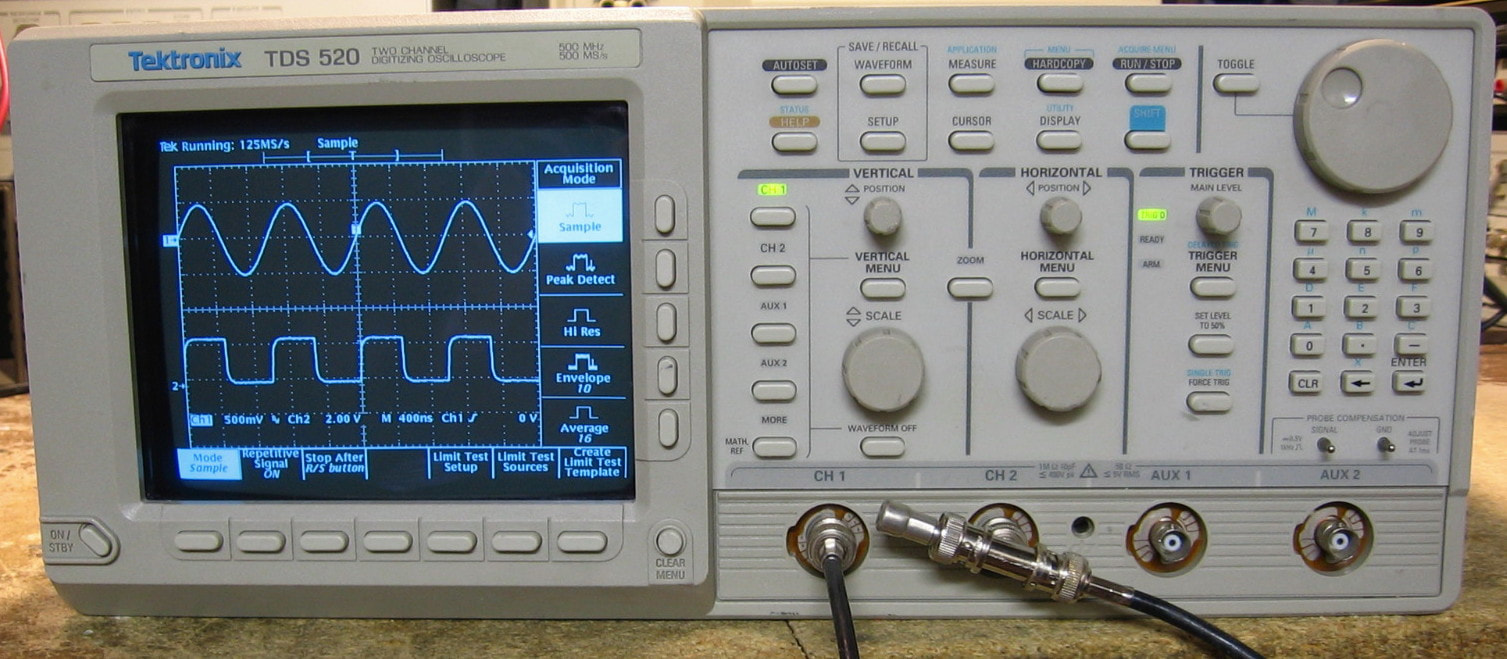
Tektronix TDS520: Two+ channel 500 MHz digital scope. It actually has 4 channels, but the last two are called Aux1 and Aux2 and have limited vertical sensitivity choices. Moreover, there are only two digitizers, so you can only do two channels out of the four at once. While the bandwidth is 500 MHz, the maximum sample rate is also 500 MHz, so you had better be looking at repetitive signals up there. This is the earliest version of the 520; Tek eventually made an A, B, C and D version but I've deduced that my unit was built right before the 520A was introduced. Life is too short for me to figure out what the improvements were from model to model. Very similar to my TDS350 described above, but a whole lot faster, better specs, and a few more functions, measurements and menu items. However, and this is a BIG however, calibration can only be done using a long-gone Tek piece of software running on a DOS 3.x machine with a specific GPIB card. People who have tried to do it claim it is a total hit-or-miss proposition. Fortunately, mine seems spot-on and I really don't see how much it could change anyway (unlike pure analog scopes like my Tek 7000 series, there isn't much stuff in a "modern" digital scope that can wander over time). (PDF) Grade: A-
Postscript: I recently found a hack on the web that enables Option 2F which adds FFT, Differentiation and Integration to the math functions. The hack only involves changing two bytes in the NVRAM, so out it came, changed the bytes, and reinstalled. I guess the hack is somewhat incomplete since the startup screen still does not show any options installed. But the new functions show up in the menus and work just fine. Like most FFT functions in oscilloscopes, it is a bit of a pain to use correctly (see the HP 54522A for how an FFT should be implemented in a scope). But it is nice to have it in the TDS520 and the price, of course, was right.
The seller showed a picture of the boot-up of the machine with the "Self-Test Passed" message. That's good. He also claimed that the unit was unresponsive to inputs on both channels. That's bad. So I took a chance for $79. All of the Tek TDS500s and TDS600s suffer from leaking surface mount electrolytic capacitors whose electrolyte is very eager to chew through traces and corrode IC pins/pads. In fact, the official word is that you shouldn't even power one of these puppies up until after you have replaced all the capacitors, fixed all the severed traces, and scrubbed the board with de-greaser, alcohol, hot water, and anything else you have lying around. When I took it out of the box, I stayed true and didn't power it up - I removed the cabinet and took a look. What I saw were absolutely pristine boards with not a drop of electrolyte anywhere. Then I saw a repair label, dated September, 1999 (~6 years after my unit was built). I did see some evidence of corrosion on the capacitor pads, but I saw no board rework. A lot of the caps are installed slightly crooked and my guess is that this 520 was re-capped prophylactically before any bad leakage occurred.
At that point, I felt better about powering it up. The POST completed successfully and I took a signal and hooked it up to the scope. Evidently, the unit restored itself to the last setting which had the channel couplings set to ground and the trigger set to normal (not auto). In other words, no trace appeared on the screen. Just what the seller claimed. So I set the coupling to DC, the trigger to auto, and, of course, the scope worked perfectly fine.
When I got done laughing, I went through all the menus and verified that everything worked as expected. Except that I couldn't access any of the items using the Shift button. There is an LED that turns on when you press Shift and my LED remained unlit. Funny, though, that I could hold the Shift button down and it would lock out all of the other buttons, but the actual Shift button did not work (how this is possible is beyond me). So I disassembled the front panel and lightly cleaned the interdigitated traces on the switch board that get hit with the rubber/carbon pad upon button press. Put everything back and my Shift button now works.
Finally, I went through the Signal Path Compensation routine which is always the kicker in the Tek TDS scopes. If anything is going to fail, it is this SPC routine. But it passed on the first try, so I'm happy.
Finally, it looks like some cal constants may be stored in one of those Dallas integrated battery NVRAMs (DS1245Y-120), although there seems to be some disagreement on the internet as to whether the cal constants are stored in this NVRAM or on some EEPROMs on the firmware board. But people do agree that if the NVRAM gets scrambled, it can prevent the machine from booting up. If I can locate a suitable replacement, I may pull the chip, read it and burn another NVRAM to have as a backup. The one in there has a 1999 date code so was replaced when they did the electrolytic job. Twenty years is getting close to the end, although I have some other pieces with much older ones that are still fine.
Postscript: I procured another DS1245Y NVRAM, pulled the old one out, read it and programmed the new one. Upon installation, everything worked fine for a couple of days, then the Shift button stopped working again. This time when I pulled the front panel, I looked carefully at the component side of the board, not just the other side where the switch contacts are. Sure enough, several puddles of wet electrolyte. So I re-capped the board and that seemed to fix my Shift button problem.
Postscript^2: A few days later, the TDS520 hung on boot. The diagnostic LED on the processor board flashed a few characters, then showed ".8". Moreover, the LED was a lot dimmer than normal which is kind of strange since it goes directly to a 74HCT273 octal latch. Towards the end of the day, the LED actually went totally dark. I spent many hours trying to debug the thing and at one point was convinced that the boot ROM was bad since the service manual said the fourth byte should be FF and I was getting FE. To make a (very) long story short, I decided to do three things: 1) re-cap the processor board (since I was not 100% sure it had been done in the 1999 repair); 2) replace the 74HCT273; and 3) replace the MC68020 processor (since right after boot, the uP HALT line went active). Sure enough, that did the trick - the TDS520 is up and running flawlessly again. Unfortunately, I did all three "repairs" at the same time, so I don't know which one(s) actually fixed it. That leaves the acquisition board capacitors which I'm certain were re-capped at some time. At a later date, I might rip those ones out also since it looks like they replaced them with the same manufacturer's potentially bad caps.
Postscript^3: I decided to re-cap the acquisition board since even though it had already been done (I'm guessing in 1999) and I didn't see any active leakage, the caps are 20 years old and I don't want to take a chance. Like the processor board and the front panel board, I replaced the SMT caps with Panasonic radial electrolytics. Most were 105 deg, low ESR, but there is a shield over 2/3 of the acquisition board with very little clearance for the caps. So I was forced to use some 85 deg, general purpose Panasonic radials, since these were the only ones I could find that were small enough. Took about 4 hours and another ten bucks to replace the 45 SMT caps, but now the entire TDS520 has new caps (except for the power supply which is not any more problematic in the TDS scopes than any other). After all the SMT caps were pulled, I did some forensic analyses. I pretty much got only a few nF on all the (33 uF) caps on the processor and display boards, and the correct values (10 uF and 33 uF) on the acquisition board. At first, I thought maybe the low readings on the caps were caused by damage from me twisting them off the board, but that doesn't explain the correct readings I got using the same method on the acquisition board. So I gave a bunch of caps a squeeze with a pair of pliers. Liquid oozed out of all the ones from the acquisition board, but the processor/display caps were bone dry. The conclusion is that 1) the leaking caps on the display board were bad (obviously), the 2) non-leaking caps on the processor board were bad, and 3) the non-leaking (most likely replaced) caps on the acquisition board were good. An interesting intellectual exercise for what it's worth. Moral: on any Tektronix TDS scope with silver can SMT caps (mine were made by United Chemicon), replace them all. This is not only my opinion, it is the opinion of dozens of forum discussions on the topic. We're not kidding!
Postscript^4: Wow, this piece just keeps on giving. I had noticed that the probe compensation signal pin on the front panel was only producing 0.4V, not the approximately 0.5V that is advertised. I first thought nothing of it, but I just checked it again and it is now 0V. Rather than fool around with it further, I simply replaced the front panel with a replacement that I had purchased as insurance when I was having problems with the Shift button. Now it is exactly 0.5V. Moreover, the replacement board is Version 2 which has to be better than the original Version 1 board that was in the scope. Even though the caps looked fine on the replacement board, I did re-cap it just to be safe. Now, maybe I am done with the TDS520???
Postscript^5: The original front panel board develops the 1 kHz, 0.5V square wave probe compensation signal by taking a 2 kHz signal generated by the uP on the board, dividing it by 2, and sending it through several transistors all controlled by an op-amp. The transistor output also goes through a voltage divider made up of 100 and 2000 ohm 0.1% low TC precision resistors down to a Linear Technologies -10V reference chip. Ideally, at 0.5V output, the junction between the two resistors is at 0V, and this junction feeds the inverting input of the op-amp (the non-inverting input is grounded). What happened is that the 2000 ohm SMT resistor opened up. Thus the op-amp reached quiescence when the signal output was 0V - just what I was seeing. A new 2000 ohm resistor fixed the problem. Why the resistor failed is a mystery - it did not look corroded from any leaking electrolyte.
Postscript^6: Preemptively replaced the Rifa 0.0022 uF Y-capacitor with a non-Rifa 0.0015 uF Y-capacitor in the power supply.

Tektronix TM503: Three bay mainframe for the Tektronix 500 series plug-ins. Furnishes various AC and DC voltages and also has an NPN and a PNP power transistor on each bay for use by the plug-ins. (PDF) Grade: B-
There was nothing wrong electrically with the mainframe when I received it. However, it was pretty banged up and the front frame was cracked in half. I buttressed it with a small piece of aluminum and some screws.
Postscript: I must have tried to hot switch some plug-ins, because the fuse blew and the left compartment suddenly didn't work. A visual inspection showed two traces on the board were fried to a crisp. Oh well, I like to use de-solder braid to jumper burnt traces - it's nice and thick.

Tektronix TM5006: Six slot mainframe for the Tektronix 500 and 5000 series plug-ins. I have six 500-series plug-ins (as shown in the photo), so my three slot TM503 wasn't going to hack it anymore. Tek also made a TM506 that only services the 500 plug-ins. The 5006 is a much more complicated beast with a full switching power supply and a fan that is way too loud. (PDF) Grade: B+
Picked this up for $25 from a seller that claimed "the power supply was broken." Gee, that pretty much means all of it, right? But, alas, upon receipt it worked perfectly fine. The only fault I found was a small chip on one of the edge connectors that caused one of the contacts with the plug-ins not to be made. I shimmed it up, but if it persists, the workaround is to use one of my plug-ins that contains its own power supply, since the bad connection will then be back to an unused pass transistor in the mainframe.
Tektronix Plug-in Bonus Rant: Tek made a slew of 500-series plug-ins and followed up their "successes" with the more capable 5000 series. I can only speak to the 500-series since that is all I have. Although there are some nice ones, e.g. the AA501 distortion analyzer and the SG505 ultra low distortion signal generator, most of the plug-ins are pretty abysmal in my opinion. I would, for instance, never use my collection of plug-ins shown in the photo above to calibrate ANYTHING - the performance is way too poor. I view a mainframe populated with 500-series plug-ins as student grade, possibly useful in a trade school. If I really need a DMM, I'm going to use one of my good ones. I don't care how convenient having a lot of capability in a "one-piece" set of plug-ins is. And of course, since it is Tektronix, we have the usual needlessly complicated mechanical designs, way too small buttons, constant cam-switch maintenance problems, faulty transistor and IC sockets and thoroughly horrendous calibration procedures. Not that you can calibrate these things without having an extender cable (which I actually do!). I know some people rave about the 500/5000 setup. Either they don't get it or I don't get it.
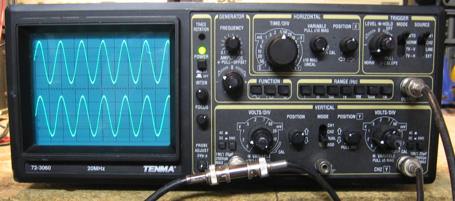
Tenma 72-3060: Basic 20 MHz oscilloscope with built-in function generator. The Tenma model is a rebadge of the Goldstar OS9030-G and is a no-frills oscilloscope with all the basic controls usually found in an oscilloscope, and nothing else. This would be an excellent teaching oscilloscope for high school students as there aren't a lot of extra specialized controls found in higher-end HP, Fluke and Tektronix models such as dual time-bases and advanced triggering. Moreover, this scope has a built-in function generator that will do sine, triangle and square up to frequencies of 1 MHz and 14 Vp-p open circuit (as you can imagine, the sine wave distortion is spec-ed at a pretty lousy 1%). Built in Korea in 2000, it is everything you would expect of a consumer grade piece of equipment (see the BK Precision Bonus Rant below the BK Precision 1570 entry earlier on this web page), namely moderate quality PC boards and dozens of wiring connectors. I don't know how much Tenma got for this thing 20 or so years ago, probably only a few hundred dollars. But everything seems to work just fine. (PDF) Grade: B+
This unit was only $20, so how could I resist? It was advertised as having a trace, but condition otherwise unknown. When received, it was unresponsive to any signal input on both channels and the vertical position knobs did nothing. The horizontal sweep, however, seemed to be working correctly. I dissected the unit and found that the four transistors in the vertical CRT amplifier were mounted to heat sinks and floating in the breeze; they had actually ripped many of the transistor leads out of their holes and destroyed many of the solder landings and nearby traces. I managed to put it all back together and point-to-point wire everything back. Now I had some signal traces, but they were pretty bad. I checked the 140 V power rail and found about 50 V of ripple on it. When I pulled the main filter cap, I saw the puddle of electrolyte beneath it and one of the leads had crumbled into dust. That cap was suitably replaced and now everything sprang to life. Except all was not right as the traces had a bit of echo on them. In other words, one saw the trace with a dimmer set of traces reaching about 1 mm to the left and right. A day was spent tracing through the horizontal circuitry and everywhere I looked, I saw the sweep ramp signal with a small amount of ~250 kHz oscillations. As there was nothing in the scope that ran that fast (at low time/div settings), I was led back to the 140 V power supply. Indeed, the op-amp controlling the pass transistor must not be happy. And this was caused by the 10 uF , 250 V output electrolytic that was also leaking - it measured only about 300 nF with an ESR of >1 Kohm. I removed it and inserted a 330 uF (all I had in the junkbox rated for 250 V). What that did was cause so much inrush current at startup that it popped the 2.2 ohm current limiting resistor. So I replaced the resistor, left the 10 uF cap out of the circuit and all my ghost traces disappeared. Went through the cal procedure and everything calibrated properly. One of these days I will replace the cap. Cheap, no-name 85 degC caps - worthless!
Postscript: Since two of the 5 electrolytics on the 195 and 140 volt power supplies were bad, I decided to replace those and all the remaining caps on the power supplies. Good thing I did since 10 out of 11 tested at least 50% low and/or had high ESRs. The entire scope should probably be re-capped, but I will wait until something actually breaks before doing that.
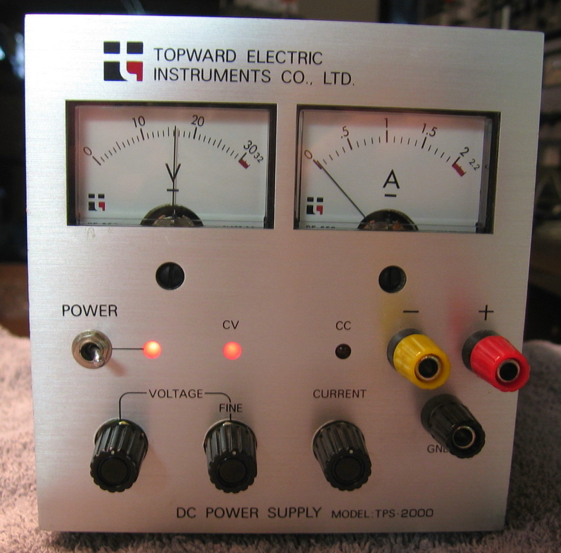
Topward TPS-2000: Basic no frills 30V, 2A supply. Literally pulled this out of a garbage can. What kind of sick person would throw this in a garbage can in the first place? (PDF) Grade: B+
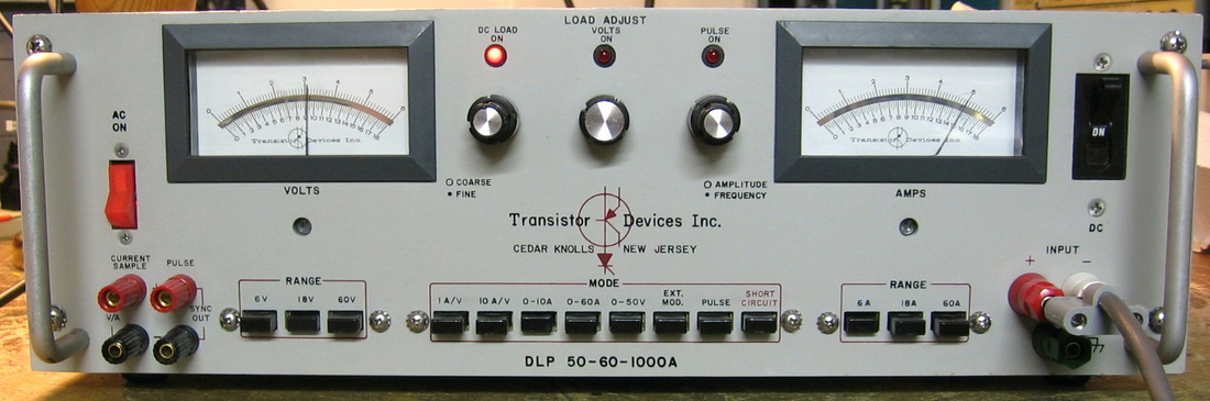
Transistor Devices DLP-50-60-1000A: A dynamic electronic load rated at 50V, 60A and 1000W maximum. Has constant I, constant R and constant V modes as well as an adjustable pulse (square wave) load. A very simple design containing one op-amp and 22 power transistors. The other electronic load I have, the ACDC EL-750B, is much more thoughtfully designed. (PDF) Grade: A-
This unit was described by the seller as, "this unit has been powered up but was found to have issues. There appears to be a short somewhere on the DC input as it does not work correctly." Sounded to me like one of the pass transistors, which are all in parallel, was fried. And that was exactly the problem - one of the 22 2N3055s had a C-E short. One of my more simple fixes.
This unit was described by the seller as, "this unit has been powered up but was found to have issues. There appears to be a short somewhere on the DC input as it does not work correctly." Sounded to me like one of the pass transistors, which are all in parallel, was fried. And that was exactly the problem - one of the 22 2N3055s had a C-E short. One of my more simple fixes.
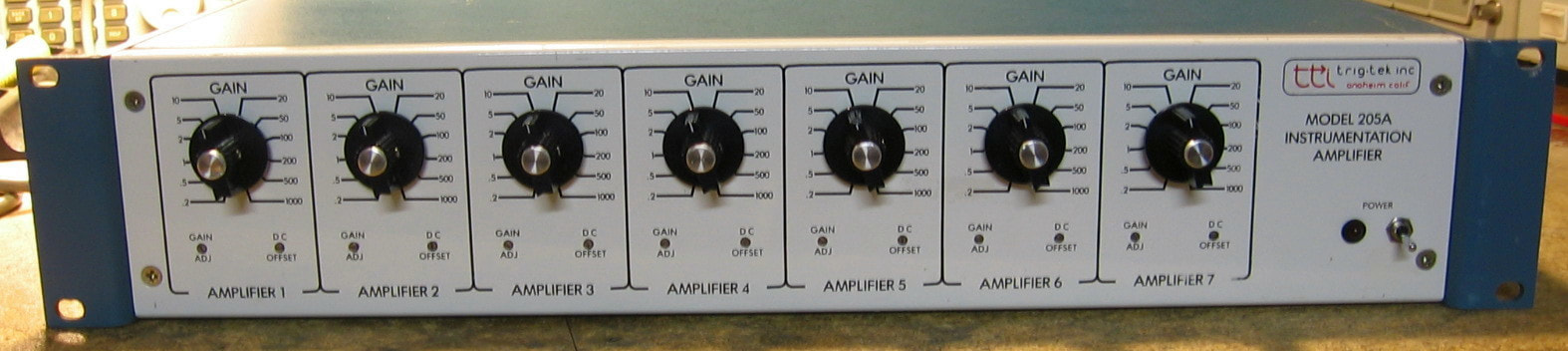
TrigTek 205A: Seven channel instrumentation amplifier. The 205A will do DC to 100 kHz with a maximum output of 10 Vp-p. The gains are selectable in 12 steps from 0.2 to 1,000, and there is also a Vernier adjustment on the front panel. The input jacks are isolated so you can run a true differential input signal. Conceptually, this piece is very easy to use; however, the large gains can create havoc if you are not careful with ground loops, impedances, etc. Build quality is so-so and each channel uses a set of CD4066s to decode the gain switch, a few LF356s and a pair of OP05 op-amps. (PDF) Grade: B
Advertised as powers up, that might have been true when it was shipped. When I received it, the two PC-mount power transformers had cracked off their mounts and turned into two one pound boulders bouncing around the insides. Fortunately, the two transformers had part numbers and were easily obtained from Mouser. However, when installed, the piece had no 12 VDC and was therefore dead. Turns out that one of the transformer bowling balls had knocked the 7812 regulator loose. After that was repaired, the piece sprang to life. While running through the cal procedure, I noticed two of the amplifiers were a bit dodgy. Trial and error was used to identify two LF356s that were faulty.
Advertised as powers up, that might have been true when it was shipped. When I received it, the two PC-mount power transformers had cracked off their mounts and turned into two one pound boulders bouncing around the insides. Fortunately, the two transformers had part numbers and were easily obtained from Mouser. However, when installed, the piece had no 12 VDC and was therefore dead. Turns out that one of the transformer bowling balls had knocked the 7812 regulator loose. After that was repaired, the piece sprang to life. While running through the cal procedure, I noticed two of the amplifiers were a bit dodgy. Trial and error was used to identify two LF356s that were faulty.
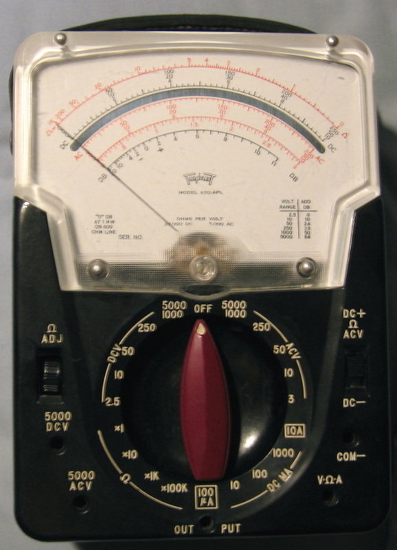
Triplett 630-APL: The Triplett version of the Simpson 260. Simply not as good. Also have a 630-PL2 (not shown). I guess some people like the Triplett meters better than the Simpson meters, but not me. It must be a Coke vs. Pepsi kind of thing. (PDF) Grade: B-
Both had missing and/or burnt resistors. Certainly easy to fix these. Had three, gave one to WA1MIK.
Both had missing and/or burnt resistors. Certainly easy to fix these. Had three, gave one to WA1MIK.
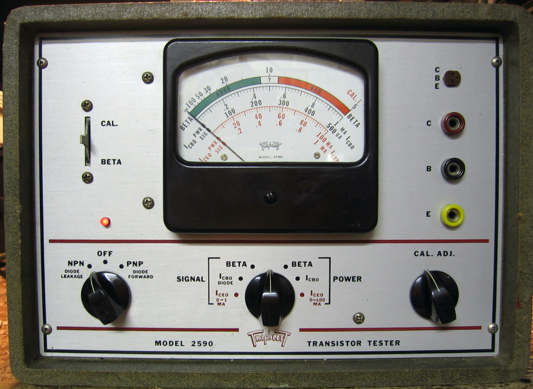
Triplett 2590: Transistor beta and leakage meter. A somewhat useful relic from the 1960s. This thing will test power transistors using a lot of current. Can fry a transistor if you are not careful, especially if the transistor is out-of-circuit and not properly heatsinked. (PDF) Grade: B+
V, W : Valhalla, Vector-Vid, Wandel & Goltermann, Wavecrest, Wavetek
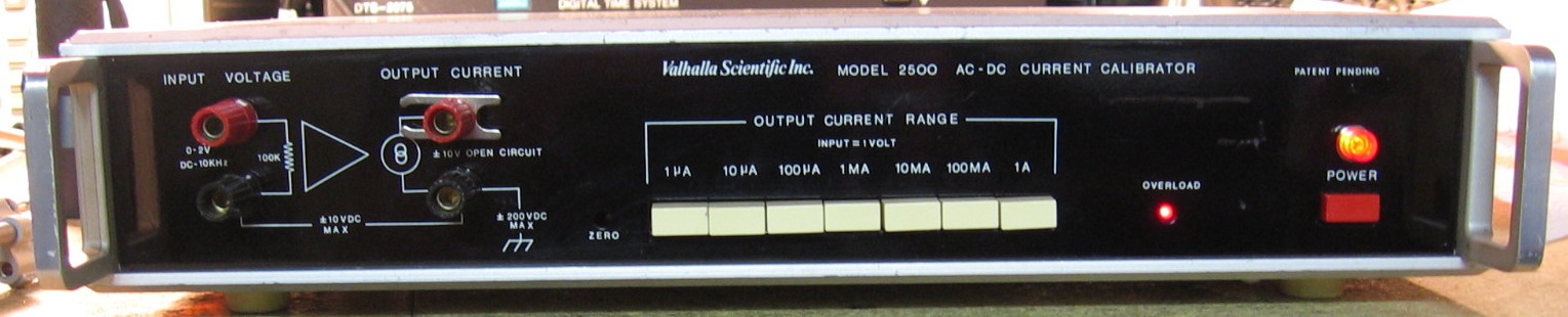
Valhalla 2500: AC/DC current calibrator. The 2500 is a wideband voltage-to-current converter that will convert a precise input voltage to a proportional output current. It provides seven current ranges from 1 uA to 1 A. The maximum output current for each range is achieved when the input voltage is precisely 1.0 volts and scales down exactly from there. In other words, if you want 3.14 mA, set the 2500 to the 10 mA range and input 0.314 volts. It will do DC with both polarities and AC up to 10 kHz. The basic accuracy is 0.01% (DC) and 0.05% (AC). It only has an anemic 10 volt output compliance, but the good news is that it can be over-ranged to 2 amps with a 2 volt input. Not much going on inside - a few op-amps, some 0.05%, 5 ppm/degC precision resistors, and a pair of push-pull TO3 output transistors. Built in the late 1970s, the build quality is surprisingly poor. And whoever had it last must have run it at full load 24 hours a day for years because the four 1 ohm, 8 watt load resistors haven't just discolored the board underneath, they have actually melted the board. Not as good as my North Hills CS152-7 current calibrator, but it will do in a pinch. (PDF) Grade: B
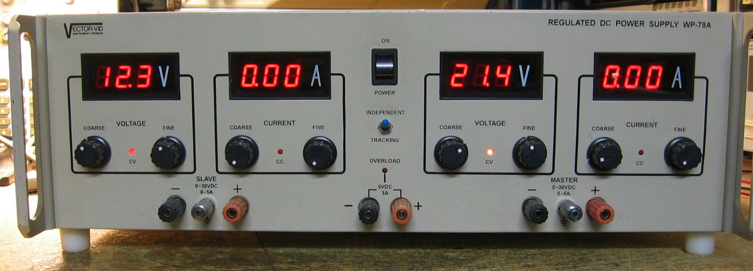
Vector-Vid WP-78A: Triple output power supply. Even though I do have enough power supplies, one can never have enough power supplies. This one is pretty powerful, having two 30V, 5A independent (or tracking) and one fixed 5V, 3A supplies. And that's about it. Why oh why do manufacturers mount the binding posts without the standard spacing? A first glance inside this piece reveals a very well thought out design with a massive transformer. However, they really did use very cheap parts in order to get the cost down. Like the Fluke 382A calibrator, they keep the pass transistor dissipation at a minimum by using an SCR to throttle the input voltage to a few volts over the output voltage. A very basic power supply without the sense terminals or remote configuration as found in more expensive units. And I'm pretty sure the unit was made in India of all places! (PDF) Grade: B+
Picked this up for about $25 in non-working condition. When received, the left-hand supply was stuck at 37V output and the two digital readouts were dark. The right-hand supply produced no output, although the displays were lit up. The fixed 5V supply was fine. Visual inspection revealed the Molex connectors from the transformer to the input of the two supplies were burnt to a crisp. This was probably a marginal design decision to use these connectors seeing as many amps could be going through them. Without having a set in my junkbox, I was forced to file and clean the connectors (both male and female) as best I could. That got the right-hand supply working, but the left-hand supply was still stuck at 37V with no display. I pulled the board out only to find a 79L05 regulator cracked into two pieces. That was replaced with an ordinary 7905 from the junkbox (which turned out to be bad and cost me about an hour to figure out what was still wrong!). I did pull the input and output electrolytic caps surrounding the 79L05 and they were both about 50% low with ESRs > 20 ohms. So they were replaced, and given that observation, I'm going to replace all the cheap no-name electrolytics in this piece. The schematic I was able to get on-line was for a different model, but very close to mine, and from the schematic I was able to figure out how to properly align the piece.
Postscript: Replaced the 30 or so electrolytics with good Nichicon 105 degree rated caps. Also removed the Molex connectors and replaced them with European style terminal blocks. Most of the caps that I removed tested OK, but there were a few 10 uF jobs with very high ESR. Should be a better unit now.
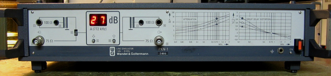
Wandel & Goltermann PKN-1: The PKN-1 is a cable simulator for digital communications, notably T1 lines. One simply clicks the up or down buttons to adjust the attenuation to anywhere from 0 to 40 dB. The group delay of the simulated cable is also then inserted automatically. These units were used by modem manufacturers to eliminate the need to use thousands of feet of cable to test their designs. The reason the PKN-1 was designed for T1 is given by the normalized frequency of 772 kHz as one can see on the graphs printed on the front panel. Inside the unit is a bank of active filters that gets switched in depending upon the attenuation setting. As with all W&G equipment, a joy to examine. The unit I bought ($25 + shipping) was particularly clean, but manuals of any kind nowhere to be found. This might also be the lowest button count piece of 19" test equipment I have! (--) Grade: A-
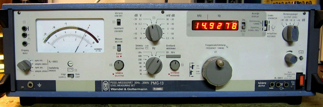
Wandel & Goltermann PMG-13: Selective level receiver (for audio frequencies) similar to the HP 3581C. Rated to 20 kHz in narrowband mode and 50 kHz in broadband mode with measurements from +22 to -90 dBm (re 600 Hz). Displays frequencies to 0.1 Hz resolution and has a built in tracking generator. Has IF filter bandwidths from 1.6 kHz down to 10 Hz, balanced/unbalanced and bridged/terminated input selections. The best case accuracy is about +/-0.2 dB. The PMG-13 is not as good, however, as the HP 3581C because it lacks sweep capability and has about 10 dB worse dynamic range. One has to be careful when looking at weak harmonics of a strong fundamental not to overload the mixer by down-ranging the amplitude control. My biggest complaint is that the inputs/outputs use banana jacks and these use a non-standard spacing (thanks a lot W&G) preventing the use of a BNC-banana adapter. Like all W&G equipment, the PMG-13 is superbly engineered and the level of workmanship is something to behold. (PDF) Grade: B+
Electrically this piece was fine as received other than a 0.4 A fuse being installed instead of the recommended 0.8A fuse. But it draws <25 watts from the AC line and I don't have the correct fuse anyway, so 0.4 A it shall be. I'm sure the unit could be tweaked a little better with a thorough calibration, but the calibration procedure is not included in the manual and the manual is in German anyway. Mechanically, the front panel was an absolute disaster - about the worst I've ever had. I did my best to clean it up, fix the broken knobs, fix the broken input jacks, etc. Let's just say it looks a whole lot better when it is sitting in the darkest corner of the lab.
Electrically this piece was fine as received other than a 0.4 A fuse being installed instead of the recommended 0.8A fuse. But it draws <25 watts from the AC line and I don't have the correct fuse anyway, so 0.4 A it shall be. I'm sure the unit could be tweaked a little better with a thorough calibration, but the calibration procedure is not included in the manual and the manual is in German anyway. Mechanically, the front panel was an absolute disaster - about the worst I've ever had. I did my best to clean it up, fix the broken knobs, fix the broken input jacks, etc. Let's just say it looks a whole lot better when it is sitting in the darkest corner of the lab.
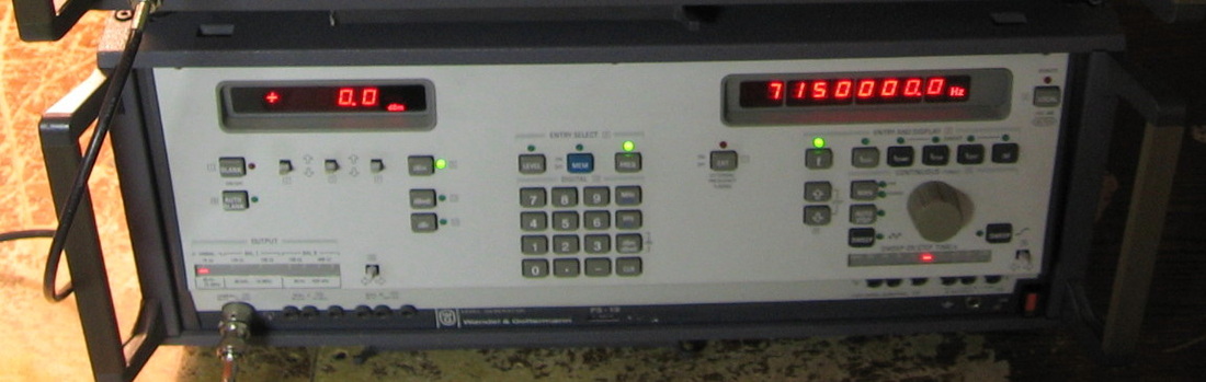
Wandel & Goltermann PS-19: Companion signal generator to the SPM-19 Selective Level Receiver. A decent standalone generator too, but the knobology leaves a little to be desired. Typical W&G German overengineering - all the circuit boards are in their own little sealed compartments. (---) Grade: A-
Replaced T13 LED driver transistor on frequency display board.
Postscript: One day I turned the piece on and I heard a pop. Moreover, the display kept flashing error 1-103 and there was no output. When I opened it up, I was met with the stench of a blown tantalum capacitor, despite the fact that most of the circuitry is in little sealed compartments. When I finally located the right board, the tantalum had obviously caught on fire and had charred many of the surrounding parts. I don't have a schematic for the PS-19, so all I could do was throw in a 22 uF tantalum and hope for the best. Seems to be fully functional now.
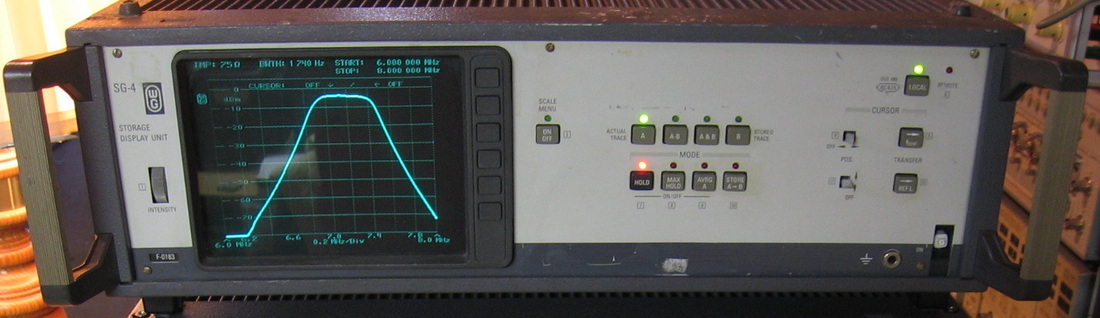
Wandel & Goltermann SG-4: Display unit working in conjunction with SPM-19 and PS-19. Set the SPM-19 frequency span and sweep rate, then it controls the PS-19 generator and the SG-4 graphs the results. Instant spectrum analyzer with tracking generator. Nowhere near the build quality as the W&G PS-19 and SPM-19. (---) Grade: B+
When I received this, it powered on, immediately stopped and displayed "SPM-19?" That's because it wasn't yet hooked up to the SPM-19. The connection requires a 14 pin analog cable and a 24 pin GP-IB-like cable, neither of which I had. After making those up, I got past the initial hangup and it now said "GP-IB?" That's because the parameters on the GP-IB board in the SPM-19 were set wrong. Now I do not have the manual for the GP-IB board in the SPM-19 and the board has about 10 reconfigurable jumpers on it. In fact, the SPM-19 didn't originally have a GP-IB board - I pulled it out of the PS-19 since I knew the PS-19 could be controlled with analog cables (confused yet?). Obviously the GP-IB board was configured for the PS-19, not the SPM-19. In fact the part number for the right GP-IB board for the SPM-19 did not match the PS-19's GPIB board that I stuck in. But, what the hell, a GP-IB board is a GP-IB board is a GP-IB board... So what I did was to hook up a National Instruments USB-GP-IB controller to it and moved the jumpers around until my computer showed I was communicating successfully. Once I did that, the hookup to the SG-4 went smoothly and the SG-4 works fine.
When I received this, it powered on, immediately stopped and displayed "SPM-19?" That's because it wasn't yet hooked up to the SPM-19. The connection requires a 14 pin analog cable and a 24 pin GP-IB-like cable, neither of which I had. After making those up, I got past the initial hangup and it now said "GP-IB?" That's because the parameters on the GP-IB board in the SPM-19 were set wrong. Now I do not have the manual for the GP-IB board in the SPM-19 and the board has about 10 reconfigurable jumpers on it. In fact, the SPM-19 didn't originally have a GP-IB board - I pulled it out of the PS-19 since I knew the PS-19 could be controlled with analog cables (confused yet?). Obviously the GP-IB board was configured for the PS-19, not the SPM-19. In fact the part number for the right GP-IB board for the SPM-19 did not match the PS-19's GPIB board that I stuck in. But, what the hell, a GP-IB board is a GP-IB board is a GP-IB board... So what I did was to hook up a National Instruments USB-GP-IB controller to it and moved the jumpers around until my computer showed I was communicating successfully. Once I did that, the hookup to the SG-4 went smoothly and the SG-4 works fine.
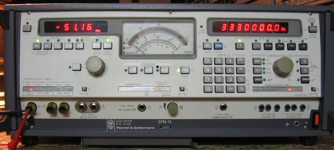
Wandel & Goltermann SPM-19: Selective level measuring receiver to 27 MHz. Has both a digital meter and an analog meter/demodulator. People have claimed that the SPM-19 has no equal and I sort of have to agree. It truly is superb. However, I can always find something to complain about, namely that when you switch to digital meter mode, it won't demodulate signals. So if you want to use this thing as an ordinary radio, you have to leave it in analog mode. The only thing I can compare it to is the HP 3586B and the SPM-19 handles the AGC much better and is more accurate. Now selective level receivers were designed for FDM measurements and as such, once the attenuation has been set, are optimized for a very small amplitude range, sacrificing the intercept point. So before one decides to use these as general purpose receivers, one might consider investing in a preselection filter, especially if you live near a 10 kW broadcast transmitter. (OM) Grade: A
When first received, the very nicely sealed switching P/S was malfunctioning. That's because one of the oil-filled electrolytics had blown its plug and sprayed oil over EVERYTHING. Fixed the P/S, which was dicey because the oil had dissolved a lot of the urethane coated wire insulation. So once it was powered up, the SPM-19 had some flaws. These were traced eventually to A14U1 (CD4028), A22U42 (CD4077) and A21U71 (CA3096). After replacing these, the unit worked until one day - bam - dead P/S. At this point, the hell with it. I ripped out the P/S and built my own using a Meanwell 120W switching supply, an external 6V regulator and a transistor switch. Works like a champ.
Postscript: I took the covers off one day to snap a photo of my replacement power supply. Good thing since the two AA-batteries used for memory backup had leaked. The batteries were in a sealed plastic case, but the acid managed to leak through that too. I put in a new holder and batteries.
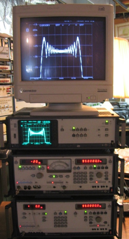
Wandel & Goltermann PS-19/SPM-19/SG-4/External: This is a picture of all three W&G units working together. An external monitor was used courtesy of a PAL-VGA converter supplied by a friend. Grade: A- (avg)
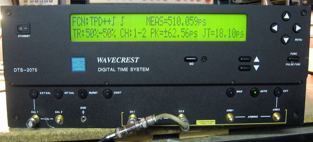
Wavecrest DTS-2075: Digital Time Scope to 800 MHz. While Wavecrest calls this thing a time scope, it really is a time interval analyzer, sort of like the HP 5371A (and to a lesser extent, the HP 5370A counter). But what a time interval analyzer it is! 25 ps one-shot accuracy, 850 fS resolution, 0.001 fS display resolution, 3 pS typical internal jitter, 10 ps average accuracy, up to 40,000 readings/sec, automatic calibration, strobing voltmeter, automatic pulse-find parameters for triggering, and on and on. Shown in the picture measuring the time delay of a 5" BNC jumper cable as 510.059 ps (using a 1000-measurement average). This unit is currently still offered by Wavecrest as is its big brothers, the 2077 and 2079, which go to 1300 and 1630 MHz respectively. There are no prices on Wavecrest's web site, but my guess is upwards of $50K for any of them. Measures the usual stuff like period, frequency, pulse width, time interval, cable delay, etc. The menu system is a bit obtuse and I did find what I think is a software bug: if you put the thing in manual trigger and complete a measurement, it hangs the machine waiting for another manual measurement with no way to get out of manual mode. It has a fairly extensive set of calibration routines - the simplest one takes about 11 minutes and requires no intervention. There are also calibration output jacks that allow you to calibrate the thing with the specific cables you intend to use for measurements. I've only scratched the surface using this piece, primarily because the user's manual is horrific and doesn't explain much. I would have expected better, but perhaps they have some application notes or white papers that I need to read to better acquaint myself with the unit's capabilities. But forget the service manual, not that you could fix this thing. Luckily, my $185 paid off and I got a working unit. (PDF) Grade: A
Postscript: On KO4BB's web site, there are a slew of app notes and manuals for Wavecrest products. Also, my unit seemed to be about 25 ps high on most measurements when compared to the HP 5370A. I could get the Wavecrest to agree if I adjusted the trigger threshold by about 10 mV. So why not try the full calibration that also sets the A/D reference points for triggering? Silly me. Now the unit is within 2 ps of the 5370A and comfortably beats the +/-10 ps tolerances on all of the performance tests (~ 2 ps).
Postscript: On KO4BB's web site, there are a slew of app notes and manuals for Wavecrest products. Also, my unit seemed to be about 25 ps high on most measurements when compared to the HP 5370A. I could get the Wavecrest to agree if I adjusted the trigger threshold by about 10 mV. So why not try the full calibration that also sets the A/D reference points for triggering? Silly me. Now the unit is within 2 ps of the 5370A and comfortably beats the +/-10 ps tolerances on all of the performance tests (~ 2 ps).
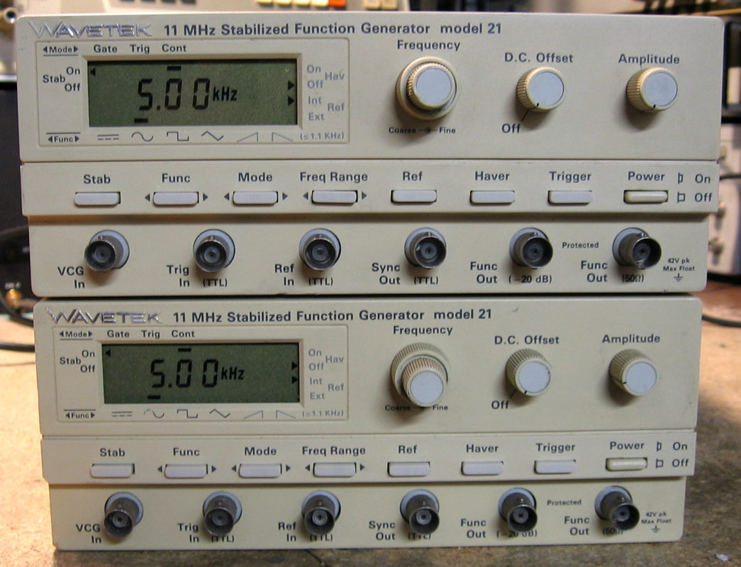
Wavetek 21: The Wavetek 21 is a 100 uHz to 11 MHz function generator producing sine, square, triangle, ramp up/down, haver-functions and DC with a maximum output voltage of 10 Vp-p into 50 ohms. It has the usual gated and trigger modes. The 3-1/2 digit LCD displays only frequency; you are on your own for amplitude and offset. Typical of many of the early Wavetek function generators, it is not particularly accurate nor is it low distortion. The thing generates signals in the usual analog fashion (charging/discharging a range capacitor from a current source) over 1.1 kHz and digitally (via a ROM-based wavetable) under 1.1 kHz. The ramp up/down and haver-functions only are generated digitally, hence they are restricted to <1.1 kHz. There is a "stabilize" button that locks the frequency to what is displayed - I guess it keeps the analog generator from drifting too much. I find this piece kind of strange both in design and implementation as it almost seems like the Wavetek engineers were learning how to build a function generator and they were experimenting a bit with the 21 model. I would give it a lower grade, but it deserves some credit since it is extremely easy to service. (PDF) Grade: B+
Two of these came in a single buy at $40 for the pair. Both were advertised as intermittent, having dirty switches and unable to get past 1.1 MHz. The first one did have some switch bounce problems, but seemed to work fine. The front panel was disassembled, the switches cleaned, and the unit calibrated nicely. I can find nothing else wrong with it. The second unit definitely had some problems in addition to dirty switches. One could, for instance, set the frequency range to 1 kHz - 10 kHz and dial in 5 kHz. Then, when pressing the Freq Range button down to the 100 Hz - 1 kHz range, instead of the display changing to the expected 500 Hz, it would read 1500 Hz (the output, however, was correct at 500 Hz. Then up-ranging back to the 1 kHz - 10 kHz range would yield 15 kHz on the display and the output would have a whole bunch of 37 MHz oscillations superimposed on the waveform. Turn the frequency knob all the way to maximum, the thing would jump back to the top of the range (10 kHz), and everything would work (the oscillations disappeared). Tracing my way through the schematic in the frequency range portion of the circuit, I found a CD4011 quad dual-input NAND chip (U8E) where all the inputs and outputs were about 2.5V - not good for a 5V CMOS level. Since the various inputs to the CD4011 came from several different chips, it was clear that the CD4011 was the culprit dragging everything down. A new CD4011 was installed, the unit worked correctly and calibrated nicely.
Two of these came in a single buy at $40 for the pair. Both were advertised as intermittent, having dirty switches and unable to get past 1.1 MHz. The first one did have some switch bounce problems, but seemed to work fine. The front panel was disassembled, the switches cleaned, and the unit calibrated nicely. I can find nothing else wrong with it. The second unit definitely had some problems in addition to dirty switches. One could, for instance, set the frequency range to 1 kHz - 10 kHz and dial in 5 kHz. Then, when pressing the Freq Range button down to the 100 Hz - 1 kHz range, instead of the display changing to the expected 500 Hz, it would read 1500 Hz (the output, however, was correct at 500 Hz. Then up-ranging back to the 1 kHz - 10 kHz range would yield 15 kHz on the display and the output would have a whole bunch of 37 MHz oscillations superimposed on the waveform. Turn the frequency knob all the way to maximum, the thing would jump back to the top of the range (10 kHz), and everything would work (the oscillations disappeared). Tracing my way through the schematic in the frequency range portion of the circuit, I found a CD4011 quad dual-input NAND chip (U8E) where all the inputs and outputs were about 2.5V - not good for a 5V CMOS level. Since the various inputs to the CD4011 came from several different chips, it was clear that the CD4011 was the culprit dragging everything down. A new CD4011 was installed, the unit worked correctly and calibrated nicely.

Wavetek 23: The Wavetek 23 is a 12 MHz function generator generating sine, square and triangle waveforms. You an also AM and FM modulate signals with external waveforms. It's somewhat odd in that it can generate sine waves either using either its function generator circuitry or its synthesizer circuitry. But the synthesizer is so much better, why would you not use it? Take the Wavetek 164 or 166 and put a digital controller ahead of it. Surprisingly good frequency stability, but the distortion > 100 kHz is not particularly good. ($CD) Grade: B
When I turned the 23 on a few years later, the display was blank and the output flashed briefly on my oscilloscope. When I opened it up, I noticed the odor of a defective tantalum capacitor. The -15V rail measured 4.4 ohms to ground, and as I was getting ready to isolate the bad cap, I noticed one whose color was brown, not the normal yellow. Replaced C171 and all is well.
When I turned the 23 on a few years later, the display was blank and the output flashed briefly on my oscilloscope. When I opened it up, I noticed the odor of a defective tantalum capacitor. The -15V rail measured 4.4 ohms to ground, and as I was getting ready to isolate the bad cap, I noticed one whose color was brown, not the normal yellow. Replaced C171 and all is well.
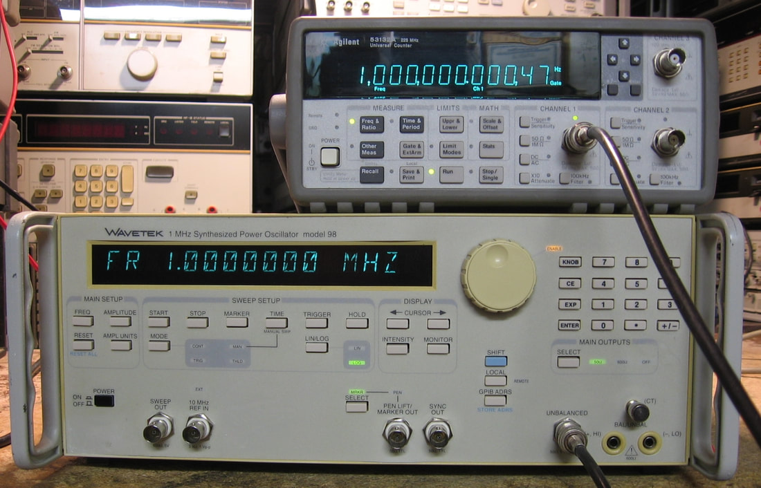
Wavetek 98: High power, 1 MHz synthesizer. The Wavetek 98 is an odd piece that generates sine waves from 1 uHz to 1.1 MHz with up to 30 Vp-p (50 ohm output into high-Z load). It also has 600 ohm balanced/unbalanced outputs in addition to the nominal 50 ohm output (frequencies and amplitudes are restricted to lower values at 600 ohms). There are some sweep capabilities and an external reference jack, but that's about it. Pretty simple to use and the architecture is the standard phase accumulator driving a sine wave look-up ROM driving a D/A driving a filter and power amplifier. Typical of these look-up table synthesizers, I'm measuring about -75 dBc distortion at 1 kHz. The Wavetek 98 is also very well constructed and quite easy to service. (PDF) Grade: A-
Advertised as a parts unit, there was a tag on the machine that said "fails frequency accuracy, possibly needs a new reference." But it was only $75 shipped, so I took a chance as the only unobtainable part is the custom Wavetek phase accumulator IC. Upon receipt, everything functioned fine, but all frequencies were 34 ppm low. The frequency accuracy spec on the unit is +/-30 ppm, yet the performance tests say +/-25 ppm. Doesn't matter because as the seller's tag said, it is out of spec. The reference is a standard 10 MHz crystal oscillator in a DIP-14 can. These things can be had for about $3, but most that I could find online were the lower grade 100 ppm stability versions. Looking around in my collection of spare parts, I came across a TXCO from my HP 5350A counter where I had replaced it with an OXCO years ago. Moreover, the TXCO was marked 10.000 MHz, had a TTL-compatible output, an adjustment screw, and ran off of 5V, just like the crystal oscillator that was in the Wavetek 98. So I pulled the crystal oscillator and installed the TXCO. As the picture shows, perfecto!
Advertised as a parts unit, there was a tag on the machine that said "fails frequency accuracy, possibly needs a new reference." But it was only $75 shipped, so I took a chance as the only unobtainable part is the custom Wavetek phase accumulator IC. Upon receipt, everything functioned fine, but all frequencies were 34 ppm low. The frequency accuracy spec on the unit is +/-30 ppm, yet the performance tests say +/-25 ppm. Doesn't matter because as the seller's tag said, it is out of spec. The reference is a standard 10 MHz crystal oscillator in a DIP-14 can. These things can be had for about $3, but most that I could find online were the lower grade 100 ppm stability versions. Looking around in my collection of spare parts, I came across a TXCO from my HP 5350A counter where I had replaced it with an OXCO years ago. Moreover, the TXCO was marked 10.000 MHz, had a TTL-compatible output, an adjustment screw, and ran off of 5V, just like the crystal oscillator that was in the Wavetek 98. So I pulled the crystal oscillator and installed the TXCO. As the picture shows, perfecto!
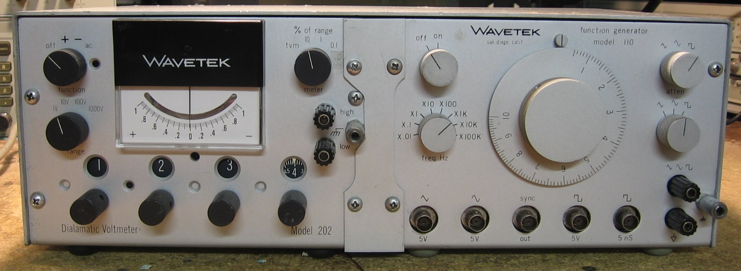
Wavetek 110: Function generator to 1 MHz. This piece is very similar to the Wavetek 112 described in the next entry and, in fact, shares much of the same circuitry. It came as part of a two-piece buy, the Wavetek 110 and the Wavetek 202 (described below). Unfortunately, the two pieces, although bolted together and easily separated, share a common top cover. So they will remain forever married. (PDF) Grade: B
Advertised in unknown condition, the 110 worked when powered on. However, seeing as it is a piece from the 1960's, it is full of leaky capacitors, weak transistors, drifty resistors, dirty sealed pots, etc. I'll just count my blessings that I didn't really have to repair this unit. But I did run through the alignment procedure and found that it was really way off as I went through it.
Advertised in unknown condition, the 110 worked when powered on. However, seeing as it is a piece from the 1960's, it is full of leaky capacitors, weak transistors, drifty resistors, dirty sealed pots, etc. I'll just count my blessings that I didn't really have to repair this unit. But I did run through the alignment procedure and found that it was really way off as I went through it.
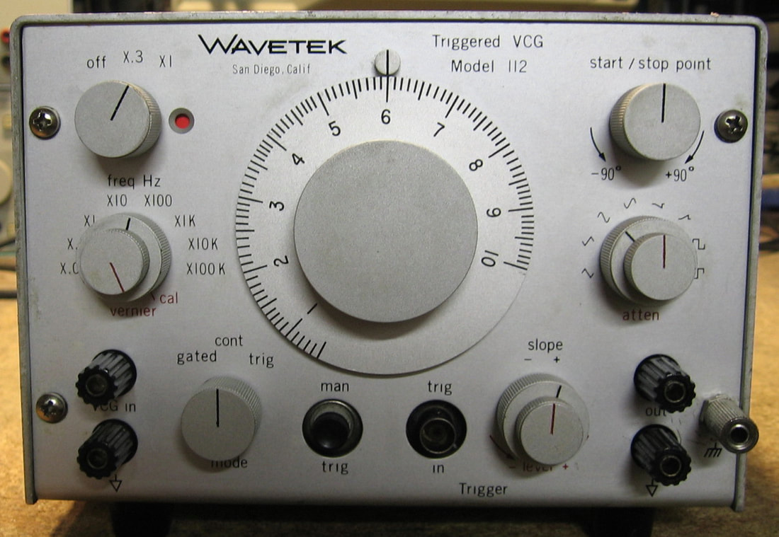
Wavetek 112: Triggered VCG. This is essentially a 1 MHz function generator doing the usual sine, square, triangle and ramp waveforms. But Wavetek calls this a triggered VCG because 1) it can be triggered or gated externally, and 2) a front panel input voltage can control the frequency. Both these "features" are commonplace with more modern function generators, but I guess in the early 1970s, maybe they were novel. The 112 does have one nice front panel control that allows the starting phase of a triggered waveform to be changed. The specs are typical Wavetek, meaning nothing very good. In fact, Wavetek refers to this piece in the manual as a "semi-precision source." However, the 112 does generate 32.5 volt peak-to-peak outputs (open load) which is somewhat rare for a function generator. They also made close variants with slightly different features, namely the Wavetek 115 and 116, as well as battery versions. Other than that, it is a pretty boring piece, although nice and compact, and just about worth the $20 I paid for it. (PDF) Grade: B
Advertised by the seller as missing a fuse holder cap, yet the front panel light glows red when powered on. Kind of impossible don't you think? Well, the little circular window in the upper left does show red when the power switch is rotated on, but that's due to the fact that it is simply a little piece of red metal that is swung into place. Anyway, I replaced the fuse holder cap and powered the unit on. It basically generated waveforms but they had a large positive bias and an even larger 120 Hz negative pulse. The output amplifier runs off of +24 and -24 volt rails and clearly the culprit was the -24 volt rail. And since the pulsing was at 120 Hz, that points to the main filter capacitor for that negative power supply. And so it was. A simple replacement of the 1000 uF cap fixed the unit (the old cap tested completely open). I do want to comment on the construction of this piece. For the most part, it is pretty well designed for an early 1970s piece. But they mount the (rotary) power switch on the back panel and the front panel knob is connected to a metal shaft running the length of the piece to the switch on the back. But the internal circuit construction uses a backplane on the bottom and five PCBs sticking up vertically from that. So they simply drilled a hole through all of the boards and ran the shaft through all of them. Kind of funny.
Postscript: I should have tested these thing a bit more thoroughly. Although spec-ed to 1 MHz, it will only achieve 700 kHz. I tried changing the integrating capacitor (on the highest 100K range) and I could get it up to 1 MHz. But then, the low end wouldn't go down to 100 kHz. There are some padding resistors and I played a bit with those without real success. However, virtually every old carbon resistor in this unit tests about 50% high - some were 3x the nominal value. Moreover, there seems to be about 50 pF of residual capacitance across the circuit with the integrating capacitor removed (possibly due to contamination inside the sealed range switch or on the circuit board). In light of these observations, there probably isn't an easy fix and I will simply live without the extra 300 kHz at the top. Otherwise, the unit performs flawlessly.
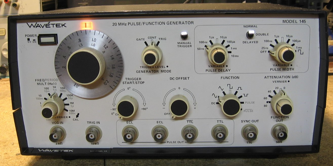
Wavetek 145: 20 MHz function generator with a few more controls for pulse generation. Rather than bore you with the specs, let me comment about the build quality which is quite cheap. The boards are single sided with lots of jumper wires. OK, it probably was cheaper to manufacture that way. But once you get the plastic top and bottom covers off, the two boards basically flap in the breeze as do the front and rear panels. Want to take one of the boards out? You literally have to unsolder >25 wires. And while we are at it, let's stack the two boards with the same orientation so that you can get to the components and adjustment pots on one board, but all you get on the other board is the solder side. Adjustment pots on the component side of the board you can't get to? No problem, we'll just drill a hole next to the pot so that you can stick a screwdriver through the hole and scrape the knob on the pot a little. I have to believe that with maybe an extra week of design time, the engineers could have made this piece ten times easier in terms of serviceability. And one or two metal clips to hold things together with the covers off couldn't cost more than a few more cents. As the repair description below will indicate, both output transistors in my unit were shorted. They are both clamped minimally to a heat sink which I think is undersized (another design fault) and probably simply burned themselves up over the years. (PDF) Grade: B
Advertised as non-functional with a note saying "50 ohm output fried." But it was only $20 and I needed a chuckle or two. When received, my ohmmeter confirmed that both output transistors (NPN-PNP push-pull configuration) were shorted. But the two transistors are either unobtainable or cost as much as I paid for the entire piece. I have an HP 8012B pulse generator parts mule and there is a push-pull amplifier in that unit. The frequency and amplitude specs for the HP 8012B are commensurate with the Wavetek 145, so I removed the two transistors and put them into the Wavetek. I mean an amplifier is an amplifier, right? The Wavetek 145 now works like a champ.
Advertised as non-functional with a note saying "50 ohm output fried." But it was only $20 and I needed a chuckle or two. When received, my ohmmeter confirmed that both output transistors (NPN-PNP push-pull configuration) were shorted. But the two transistors are either unobtainable or cost as much as I paid for the entire piece. I have an HP 8012B pulse generator parts mule and there is a push-pull amplifier in that unit. The frequency and amplitude specs for the HP 8012B are commensurate with the Wavetek 145, so I removed the two transistors and put them into the Wavetek. I mean an amplifier is an amplifier, right? The Wavetek 145 now works like a champ.
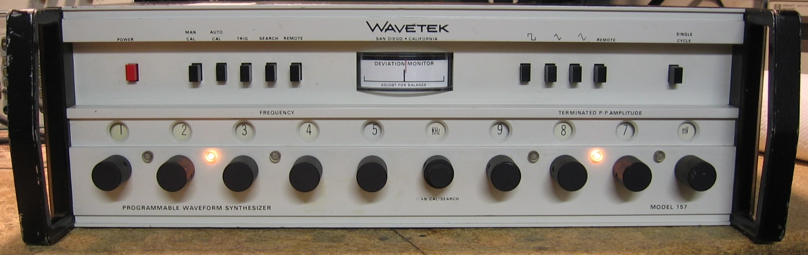
Wavetek 157: 1 MHz analog function generator. It says "Programmable Waveform Synthesizer" on the front panel, but it mostly is a function generator using the standard triangle integrator. At low frequencies (<100 Hz), it is actually a digitally implemented synthesizer, however. The specs are pretty good (~1% amplitude and 0.005% frequency). It uses a counter to measure the frequency and closes the loop back to the integrator. Although usually operated in the "auto" mode, there is a search mode that uses a front panel potentiometer to change the frequency. A deviation meter shows when the frequency matches the numerical dial settings. The 157 is somewhat similar to my Exact 605 function generator, but it annoyingly has the output jack on the back panel. What is most surprising about this piece, designed in the late 1960's and manufactured in 1975, is that it is full of old Motorola 800 and 900 series RTL chips; no TTL to be found! But it seems to be quite well designed and worthy of it's $3,000 price tag 50 years ago. (PDF) Grade: A-
Advertised as condition unknown, there was no current draw when I flicked the power switch. After cleaning the switch, the unit powered on but produced no output at the jack. Tracing through the circuit showed that everything was correct going into the final attenuator board, so that is where the problem had to be. The attenuator board has two pads controlled by two transistors and four SPDT reed relays. One of the 2N3638 transistors was cracked in half and suitably replaced by a more capable 2N3906. But that still did not fix the problem and further diagnosis showed that the coil of one of the four relays was open. The relay was replaced and all seemed OK, but what caused the transistor to explode and the relay to burn out? A quick check of the power supply revealed that the =24V used to control all of the relays was actually at -32.5V, so no wonder that the -25V rated 2N3638 popped. What is surprising is that the 157 contains about 45 of these transistors and relays (used for the frequency and amplitude digits) and none of these popped. I guess I was just lucky. Anyway, the faulty power supply was due to a bad TIP30 pass transistor which was replaced with a TIP42C from my junkbox. The only other thing I had to do was install a proper AC receptacle on the back panel. The 157 uses the "old" style rounded AC plug and the previous owner, not having the proper cord, removed the receptacle and simply ran the AC cord through the hole and hard-wired it to the fuse/switch/ground. I restored things to original.
Advertised as condition unknown, there was no current draw when I flicked the power switch. After cleaning the switch, the unit powered on but produced no output at the jack. Tracing through the circuit showed that everything was correct going into the final attenuator board, so that is where the problem had to be. The attenuator board has two pads controlled by two transistors and four SPDT reed relays. One of the 2N3638 transistors was cracked in half and suitably replaced by a more capable 2N3906. But that still did not fix the problem and further diagnosis showed that the coil of one of the four relays was open. The relay was replaced and all seemed OK, but what caused the transistor to explode and the relay to burn out? A quick check of the power supply revealed that the =24V used to control all of the relays was actually at -32.5V, so no wonder that the -25V rated 2N3638 popped. What is surprising is that the 157 contains about 45 of these transistors and relays (used for the frequency and amplitude digits) and none of these popped. I guess I was just lucky. Anyway, the faulty power supply was due to a bad TIP30 pass transistor which was replaced with a TIP42C from my junkbox. The only other thing I had to do was install a proper AC receptacle on the back panel. The 157 uses the "old" style rounded AC plug and the previous owner, not having the proper cord, removed the receptacle and simply ran the AC cord through the hole and hard-wired it to the fuse/switch/ground. I restored things to original.
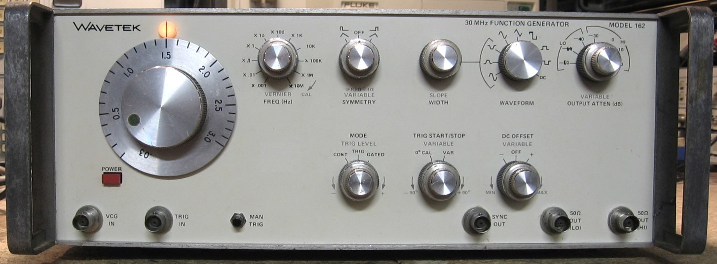
Wavetek 162: 30 MHz function generator. The Wavetek 162 is essentially a Wavetek 164 without the sweep board. The P/S and main boards are virtually identical between the two units. The date codes on the 162 show it is earlier than my 164 by about 10 years. Both the 162 and 164 do what they do, albeit the pulses start to look awkward approaching 30 MHz. See the comments for the Wavetek 166 below. There is simply no reason to buy a Wavetek 162 given that I have the 164, but the last few pieces I've bought have either worked out of the box or were easy 10 minute fixes. I wanted one that would give me a few days of repair entertainment and the price ($35 shipped) was just right. I wasn't disappointed this time. (PDF) Grade: B
Advertised as "no output," when I took the 162 out of the box, the rear panel, which holds the P/S board, was partially detached. I pulled off the rear panel only to find that the connector to the main board was disconnected. But while I had the P/S separated from the main unit, I decided to check the 15, -15, 24 and -24 DC voltages. The positive voltages were fine, but the -15 and -24 measured about -19 and -30 VDC respectively. While I pondered the tedious task of removing the P/S board from the rear panel, I plugged the assembly back into the main unit and fired the 162 up. Now all four P/S voltages were correct. I know that switching power supplies usually require a load to operate properly, but I've only seen one linear supply act up without a load and that was caused by an open filter capacitor (and the loaded voltage was incorrect anyway). The 162 uses four linear supplies and the negative and positive supplies are basically identical, so why did the positive supplies work correctly without a load but the negative supplies didn't? Nonetheless, with the 162 running, I did not get any output as the seller correctly stated. I noticed that there was no sync pulse output either and this means that not only are the preamps and output amps not working, but the basic triangle generation, from which everything is derived, probably isn't working either. Running through the diagnostic flow charts in the service manual was an exercise in futility and revealed nothing. Eventually I found the culprit - R105, a 10 ohm resistor burned out (there were burn marks on the resistor and the PCB) and measured 600 ohms. This was enough to cause an incorrect voltage (through a Zener diode) to an FET that was part of the hysteresis switch, the circuit that changes the current direction of the integrating capacitor. I'm not sure why R105 burned up since there is only about 0.3 V across it in normal operation. Perhaps another faulty component drew too much current and has previously been replaced. Once R105 was replaced, the frequency generation worked fine, but there was still no output at the front panel. Tracing through the signal path, I found a bad Q22 in the triangle amplifier and a bad Q57 in the output preamplifier. I replaced the 2N3563 and 2N5139 transistors with 2N3904/6 variety - they should be fast enough for a 30 MHz circuit. I also replaced the burned out front panel bulb with an LED and epoxied back together the broken right front handle.
Advertised as "no output," when I took the 162 out of the box, the rear panel, which holds the P/S board, was partially detached. I pulled off the rear panel only to find that the connector to the main board was disconnected. But while I had the P/S separated from the main unit, I decided to check the 15, -15, 24 and -24 DC voltages. The positive voltages were fine, but the -15 and -24 measured about -19 and -30 VDC respectively. While I pondered the tedious task of removing the P/S board from the rear panel, I plugged the assembly back into the main unit and fired the 162 up. Now all four P/S voltages were correct. I know that switching power supplies usually require a load to operate properly, but I've only seen one linear supply act up without a load and that was caused by an open filter capacitor (and the loaded voltage was incorrect anyway). The 162 uses four linear supplies and the negative and positive supplies are basically identical, so why did the positive supplies work correctly without a load but the negative supplies didn't? Nonetheless, with the 162 running, I did not get any output as the seller correctly stated. I noticed that there was no sync pulse output either and this means that not only are the preamps and output amps not working, but the basic triangle generation, from which everything is derived, probably isn't working either. Running through the diagnostic flow charts in the service manual was an exercise in futility and revealed nothing. Eventually I found the culprit - R105, a 10 ohm resistor burned out (there were burn marks on the resistor and the PCB) and measured 600 ohms. This was enough to cause an incorrect voltage (through a Zener diode) to an FET that was part of the hysteresis switch, the circuit that changes the current direction of the integrating capacitor. I'm not sure why R105 burned up since there is only about 0.3 V across it in normal operation. Perhaps another faulty component drew too much current and has previously been replaced. Once R105 was replaced, the frequency generation worked fine, but there was still no output at the front panel. Tracing through the signal path, I found a bad Q22 in the triangle amplifier and a bad Q57 in the output preamplifier. I replaced the 2N3563 and 2N5139 transistors with 2N3904/6 variety - they should be fast enough for a 30 MHz circuit. I also replaced the burned out front panel bulb with an LED and epoxied back together the broken right front handle.
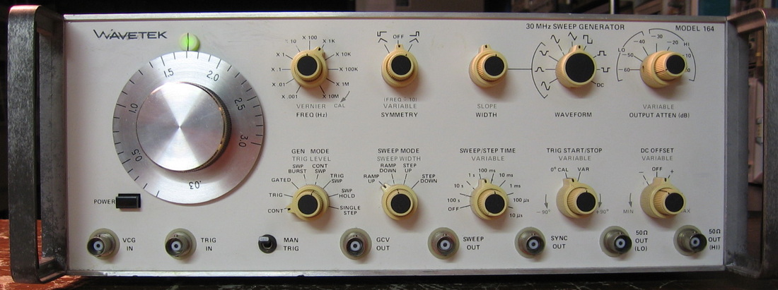
Wavetek 164: The 30 MHz version of the Wavetek 166. Same comment as for the 166. ($CD) Grade: B

Wavetek 166: 50 MHz function generator in the usual Wavetek style of "do a lot of different things, but don't do any of them with any kind of fidelity." It has loads of control over the waveform parameters, sweep rates, etc. - more than most function generators. I guess trade schools liked Wavetek stuff because it was cheaper than HP stuff. But there is nothing particularly distinguished about them. And their calibration procedures are very cumbersome. They tend to use these potentiometers that will move with the slightest vibration. No wonder all of the pots are glued down. (PDF) Grade: B+
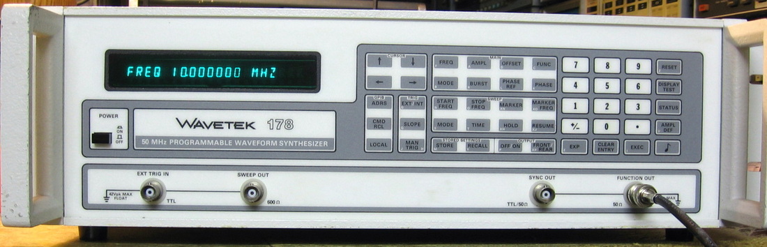
Wavetek 178: 50 MHz synthesizer/function generator. Like the HP 3325A, the 50 MHz is only for the sine and square wave functions; the triangles and ramps are only rated to a few hundred kHz. However, the digital control offers eight digits of resolution. Does the usual burst, gated and sweep functions. Built in 1990, the build quality is light years ahead of Wavetek's 1970/1980 era equipment and is every bit as good as HP. My unit also has option 002, the ovenized 10 MHz reference oscillator. The only negative thing I can say is that Wavetek chose to use membrane switches on the front panel, which often develop problems. (PDF) Grade: A-
When I last turned on this piece after several years, the display flashed and then went dark. No output either. A quick check of the 5V digital supply showed the voltage fluctuating around 3V. Occasionally it would bump up to 4.5, the display would light up, the uP would reset, but then it quickly went down to 3V and everything shut off. I isolated the P/S and all the voltages were correct (open load). I then spent a couple of hours pulling one lead of various tantalum capacitors, but it didn't help. I then disconnected the 5V supply and hooked up an external power supply. Everything sprang to life, but a few moments later, it started to reset again. When I checked the 15 and -15 volt supplies, they were both down around 12 volts and also fluctuating. At that point, I was convinced that it was a power supply problem, not something in the rest of the circuitry dragging things down. I first started working through the 15V supply. When I clipped my voltmeter on the pins of the pass transistor, the voltage was perfectly correct and everything worked fine. Whether or not there was a marginal solder joint, or some capacitor finally blew open, who knows. I touched up the solder joints on the pass transistor and ran the 178 with no issues for 30 minutes. I'll keep my eye on it.
When I last turned on this piece after several years, the display flashed and then went dark. No output either. A quick check of the 5V digital supply showed the voltage fluctuating around 3V. Occasionally it would bump up to 4.5, the display would light up, the uP would reset, but then it quickly went down to 3V and everything shut off. I isolated the P/S and all the voltages were correct (open load). I then spent a couple of hours pulling one lead of various tantalum capacitors, but it didn't help. I then disconnected the 5V supply and hooked up an external power supply. Everything sprang to life, but a few moments later, it started to reset again. When I checked the 15 and -15 volt supplies, they were both down around 12 volts and also fluctuating. At that point, I was convinced that it was a power supply problem, not something in the rest of the circuitry dragging things down. I first started working through the 15V supply. When I clipped my voltmeter on the pins of the pass transistor, the voltage was perfectly correct and everything worked fine. Whether or not there was a marginal solder joint, or some capacitor finally blew open, who knows. I touched up the solder joints on the pass transistor and ran the 178 with no issues for 30 minutes. I'll keep my eye on it.
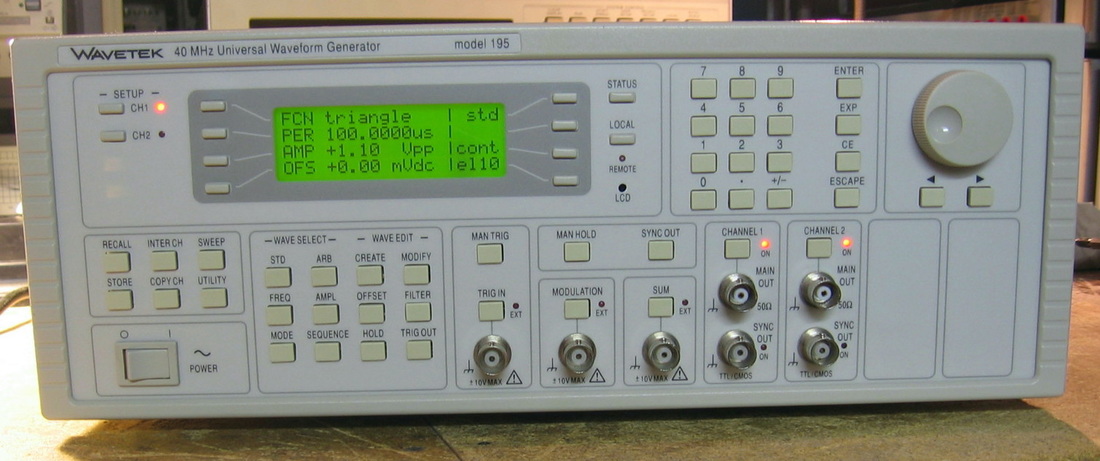
Wavetek 195: Two channel, 40 MHz arbitrary waveform generator. OK, first of all, the Wavetek 195 is an elaborate function generator that has arbitrary waveform generation capabilities. The "40 MHz" represents the fastest one can clock through the waveform memory. Since any interesting waveform better have at least two points, that gets you down to 20 MHz signals. And so on, you get the point. As a function generator, the 195 will do sine, square, triangle, ramp up, ramp down, pulse trains, sin(x)/x, haversine and more. Sine and square go to 16 MHz, pulse trains to 10 MHz and ramps, triangles to 100 kHz. Amplitude is a very nice 10 Vp-p into 50 ohms. Has an elaborate set of auxiliary functions including modulation, gating, triggering, channel synchronization and sweep. It can also sum the two channels with a flick of a button. Has 256K of waveform memory, but entering an arbitrary waveform manually is tedious at best. I really should download and try a Windows based RS-232 waveform editor. My general opinion of Wavetek function generators is that they do a lot, but none of it with any fidelity. This piece, much to my surprise and delight, does everything well. There are no transients at the corners of triangle waveforms like there are with most RC-based function generators. And there is no perceivable jitter from clocking out the waveform RAM like there is in the HP 8904. The distortion at 1 kHz was -64 dBc. The efficacy of this unit is probably why it is still being sold today ( ~$4,400) as the rebadged Fluke 282. (---) Grade: A
Advertised as "no output on either channel," I took a chance for $60 + shipping. Upon power up, I was greeted with error 127: "system ram error check battery." OK, thanks for the heads-up. The CR2032 battery was toast, so I replaced it with two AA alkalines. The error disappeared as expected, but there was no output just like the seller said. There were correct voltages present and a few red LEDs lit, but I couldn't get any relays to click and really couldn't find any signals poking around with the scope. Not even the sync outputs were present. While the front panel and uP functions all seemed correct, it really acted like the main board was dead. I can't locate a service manual, not that it would have really helped, because the board is all surface mount with a bunch of Xilinx FPGAs. I pretty much sat and played with the thing for two hours hoping some front panel setting would at least get one of the attenuator relays to click. No luck. Finally, I gave a few ribbon cables a nudge and all of a sudden, the thing sprang to life. Works perfectly now. I suppose I should go back and start wiggling the IDE connectors to see where the mechanical fault was.
Advertised as "no output on either channel," I took a chance for $60 + shipping. Upon power up, I was greeted with error 127: "system ram error check battery." OK, thanks for the heads-up. The CR2032 battery was toast, so I replaced it with two AA alkalines. The error disappeared as expected, but there was no output just like the seller said. There were correct voltages present and a few red LEDs lit, but I couldn't get any relays to click and really couldn't find any signals poking around with the scope. Not even the sync outputs were present. While the front panel and uP functions all seemed correct, it really acted like the main board was dead. I can't locate a service manual, not that it would have really helped, because the board is all surface mount with a bunch of Xilinx FPGAs. I pretty much sat and played with the thing for two hours hoping some front panel setting would at least get one of the attenuator relays to click. No luck. Finally, I gave a few ribbon cables a nudge and all of a sudden, the thing sprang to life. Works perfectly now. I suppose I should go back and start wiggling the IDE connectors to see where the mechanical fault was.
Wavetek 202: Differential Voltmeter. This piece is similar to my Fluke 887A but not as good. It boasts 5-digit readout if you include the minor ticks on the vernier dial. Will act as a voltmeter or differential voltmeter in both AC and DC modes. They call this thing a "Dialamatic Voltmerer" and Wavetek advertised this as being a big deal. All it really means is that the digit select mechanism is propagated to the next digit to the left. As an example, in a "regular" differential voltmeter like the Fluke 887A, if you want to go from 4.999 to 5.000, you have to turn three dials from 9 down to 0 and one dial from 4 to 5. In the Dialamatic voltmeter, you just turn the last 9 in 4.999 up 1 digit to 0 and the 4.99 turns automatically to 5.00. It does save time, but I don't know how much of a premium Wavetek tried to squeeze out of their customers. The 202 came paired with a Wavetek 110 function generator (see the entry for that above). ($CD) Grade: B
Advertised in condition unknown, the 202 did power up and eventually work correctly after I left it powered on for a few hours. Maybe another case of reforming capacitors. The adjustment is particularly sensitive and, like the Wavetek 110, is probably due to component age. Strangely, I found one user mod in the 202 - the addition of a 0.01 range on the upper right knob. And since the manual I have is for a different set of board revisions, I'm not about to track the mod down.
Postscript: Even with me twiddling the adjustment pots, the thing didn't want to stay settled for more than a few minutes. I replaced one of the 0.1uF capacitors in the chopper circuitry and two of the transistors, without the sockets, in the null amplifier. These three parts seemed to cause wild fluctuations when I put my finger on them. Seems a little better now.
Postscript^2: The 202 still won't stay zero-ed day to day. I replaced one of the very touchy adjustment pots with a 10-turn version for finer control. While I was doing that, I noticed a marginal connection from one wire onto a pushpin connector on the null board. Perhaps that was a big contributor to the instability. I also separated the multi-stage rotary multiplier switch and sprayed in some cleaner as this switch seemed to be a contributor to the instability when I pressed my finger on it. Anyway, the 202 is acting reasonably now provided you let it warm up for a couple of hours. That's enough repair for this not very good piece.
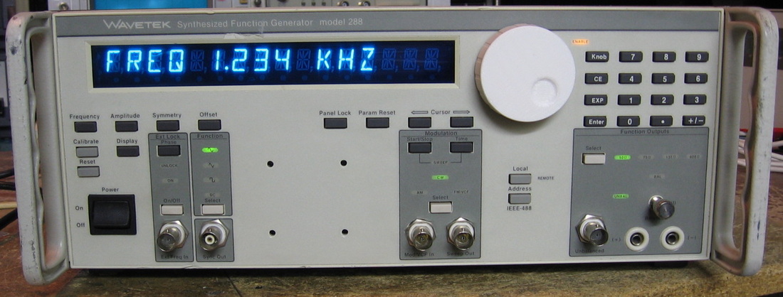
Wavetek 288: 20 MHz synthesized function generator. While the sine waves are fine, the triangle and square functions are a bit of a stretch at 20 MHz. With a 13 nsec rise/fall time, one isn't going to get very crisp square waves at 20 MHz. The accuracy specs (e.g., freq and ampl) are typical Wavetek mediocrity (1 to 3%), but when I did the performance verification, the results were MUCH better. Maybe I just got lucky. On the other hand, there is a somewhat curious 50 MHz spur at -40 dBc at output amplitudes > 1 volt. The front panel and knobology are well implemented and Wavetek does nice things like toggling the amplitude display between Vp, Vp-p, RMS and dBm. Some of the features include unbalanced and balanced outputs, selectable output impedance, AM and FM modulation, sweep functions and external phase locking and offset. The 288 was primarily built for the armed forces and has the nomenclature SG-1288/G. The four holes on the front panel was where a big Army nameplate used to be. Build quality is much better than the 164 and 166 generators, but falls a bit behind the similar-era 178. (PDF) Grade: B+
Advertised by the seller as "powers up, but displays ERR VCGZERO." It was also missing the main tuning knob cover and had one BNC jack sheared off. The BNC jack was easily replaced and a knob cover was machined at work on our 3-D printer. The service manual gives a procedure to isolate the VCGZERO error which involves pulling boards and running the automated software self-cal routines. But when I put everything back, the VCGZERO error had cleared and was replaced with a VSINE error. My conclusion was that the thing was a bit confused with the cal parameters currently stored in battery-backed up RAM. A similar kind of thing happened with the HP 8980. So I pulled the battery to clear the RAM and went through both the automated self-cal and the manual cal (adjust a few pots). All the errors went away, but the 288 powers up with a CAL REQUIRED message. It took a few tries to finally get the unit to accept the fact that all the calibrations were done and now the unit powers up correctly and works great (or as well as a Wavetek could).
Advertised by the seller as "powers up, but displays ERR VCGZERO." It was also missing the main tuning knob cover and had one BNC jack sheared off. The BNC jack was easily replaced and a knob cover was machined at work on our 3-D printer. The service manual gives a procedure to isolate the VCGZERO error which involves pulling boards and running the automated software self-cal routines. But when I put everything back, the VCGZERO error had cleared and was replaced with a VSINE error. My conclusion was that the thing was a bit confused with the cal parameters currently stored in battery-backed up RAM. A similar kind of thing happened with the HP 8980. So I pulled the battery to clear the RAM and went through both the automated self-cal and the manual cal (adjust a few pots). All the errors went away, but the 288 powers up with a CAL REQUIRED message. It took a few tries to finally get the unit to accept the fact that all the calibrations were done and now the unit powers up correctly and works great (or as well as a Wavetek could).
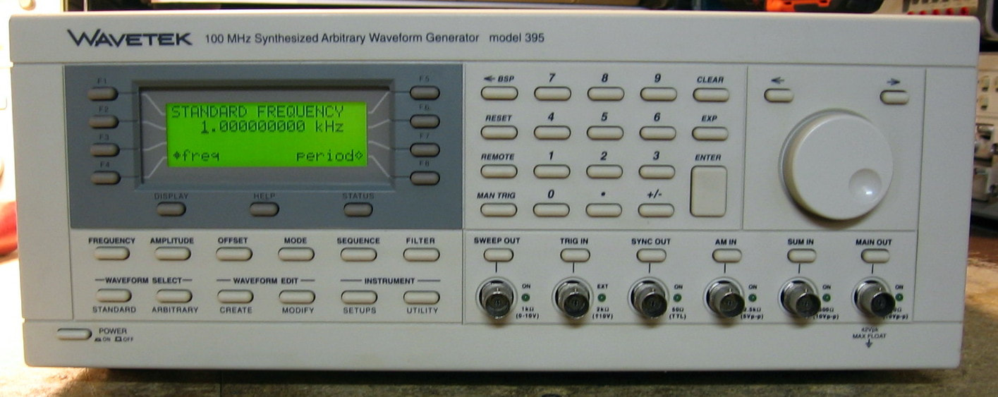
Wavetek 395: One channel, 100 MHz arbitrary waveform generator. This is the (very) big brother of my Wavetek 195 (see above) and consists of a highly diverse function generator with arbitrary waveform capabilities. In short, the 395 can generate sine, square, triangle, ramp, haversine, sin(x)/x, pulses, analog noise, digital noise and on and on. I especially like the comb function which puts equally spaced lines on a spectrum analyzer. It uses 12 bit vertical resolution, 64K waveform storage (with 1M as an option), a 100 MHz clock and has the usual gate and trigger modes, sweep generation, AM/FM modulation, etc. In fact, there is so much capability in this piece, that I really have only scratched the surface describing it. Sine wave distortion is -68 dBc proving that their table-based waveform generation scheme is very good (you can, however, see the "glitches" due to the address rounding error on the HP 53310A modulation analyzer). The man-machine interface is also pretty good and for the most part self-explanatory (it has on-line "help" on the display too). Build quality is excellent and consists of mix of surface mount and through-hole parts with several ASICs doing the hard work. All in all, a simply wonderful piece (that is still being sold today as the Fluke 291 for $4,400). I have been somewhat critical of earlier Wavetek pieces as having a lot of functionality, but none of it done with much fidelity. The 395 (and the 195 above) are fine examples of state-of-the-art function generators. In fact, I don't think any other piece comes close to the 395 in terms of how many things can be done in one box. If I was stranded on the proverbial desert island with only one function generator, this would be it! (PDF) Grade: A
This piece was your standard "doesn't power on." It uses a 3rd party 200+ watt switching power supply similar in form factor to that found in a desktop PC. That is kind of odd as the 395 only draws about 40 watts. The secondary of the supply was absolutely dead and I checked virtually every part inside except the SG8050 controller. So I ordered a few from China hoping that I didn't get counterfeits. When I received them, they had no effect on the power supply. So either the Chinese ICs were faulty or there is a mysterious failure I simply cannot find. At that point, I simply bought four $10 Meanwell supplies, gutted out the old supply, so I could still use the existing line filter, power switch and fan, and dropped in the new Meanwells (see picture below). Works like a champ although once in a while I get a "didn't power down correctly" message on the 395 upon startup. That's because the old supply had a circuit to detect shutdown and I'm no longer providing that signal. Perfectly OK, however, since one would only get in trouble if one shuts off the 395 while writing an arbitrary waveform into memory - I'm not that dumb.
This piece was your standard "doesn't power on." It uses a 3rd party 200+ watt switching power supply similar in form factor to that found in a desktop PC. That is kind of odd as the 395 only draws about 40 watts. The secondary of the supply was absolutely dead and I checked virtually every part inside except the SG8050 controller. So I ordered a few from China hoping that I didn't get counterfeits. When I received them, they had no effect on the power supply. So either the Chinese ICs were faulty or there is a mysterious failure I simply cannot find. At that point, I simply bought four $10 Meanwell supplies, gutted out the old supply, so I could still use the existing line filter, power switch and fan, and dropped in the new Meanwells (see picture below). Works like a champ although once in a while I get a "didn't power down correctly" message on the 395 upon startup. That's because the old supply had a circuit to detect shutdown and I'm no longer providing that signal. Perfectly OK, however, since one would only get in trouble if one shuts off the 395 while writing an arbitrary waveform into memory - I'm not that dumb.
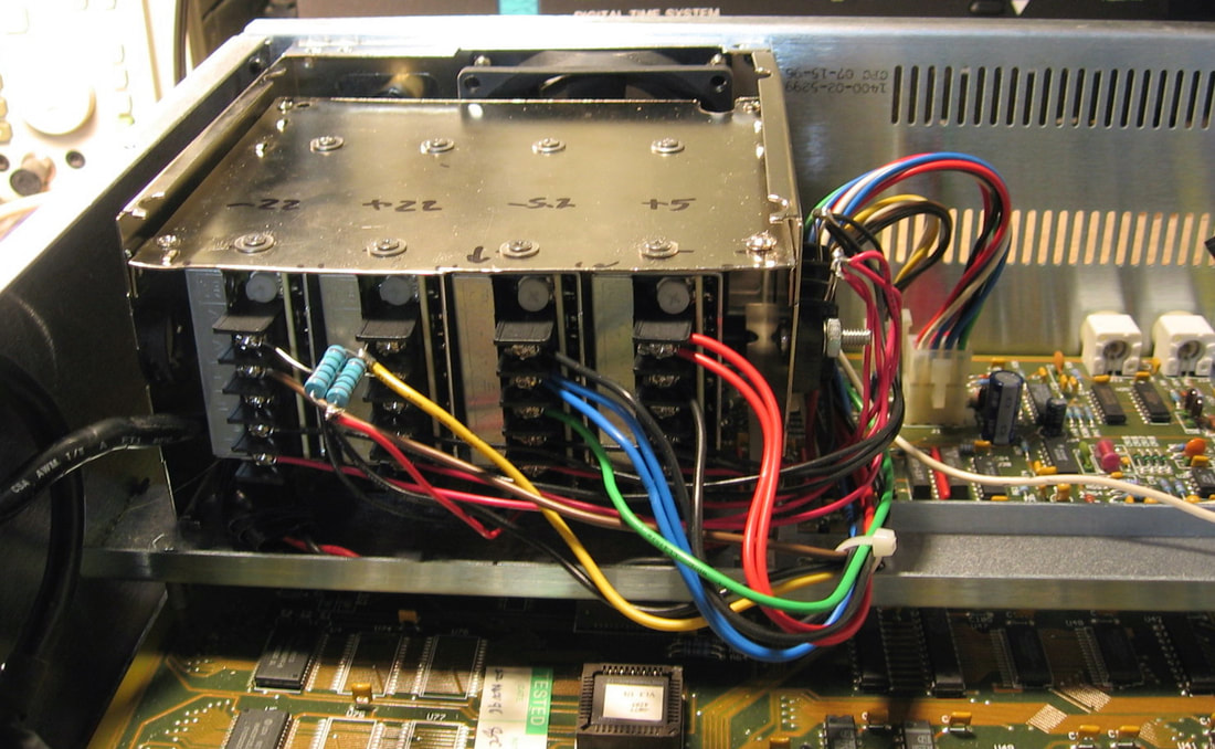
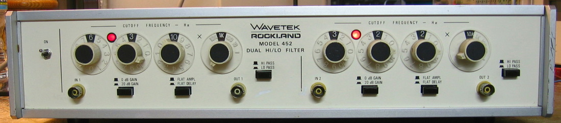
Wavetek 452: Two identical (active) filter channels, each of which has separate input/output terminals (front and rear). These filters may be used as high pass or low pass, 0 dB or 20 dB gain, Butterworth or flat delay responses and 3-digit resolution for cutoff frequency selection, with a range of 0.1 Hz to 111 kHz. The rolloff is 24 dB/octave and the dynamic range is 90 dB. Wavetek also made a more capable 852 model with 48 dB/octave filters. Not much inside except about 100 precision resistors, 40 precision capacitors, six op-amps, a bunch of rotary switches and a small power supply. (PDF) Grade: B+
I didn't expect too much to be wrong with this when I received it. About the only thing that could go bad are the op-amps. As usual, it needed a spritz or two of cleaner in the pushbutton switches. But then it seemed to function correctly until further testing revealed one problem: on the left filter only, I saw a high frequency oscillation when it was operated as low pass, flat delay. Moreover, this oscillation, at approximately 36 MHz, was only seen when the output load was 50 ohms; it was absent, for instance, on the 1 Meg input of a scope. The op-amps used in this unit are LF356 and HA5115 and the data sheets talk about putting a capacitor across output-input to move the pole around to quench oscillations. And after probing around with the scope probe (equivalent to a small capacitor), I found the right op-amp and installed a 5 pF capacitor. Funny, but when I was looking for a convenient place to solder in the capacitor, there were two holes in the board (filled with solder) right next to the op-amp and going to just the pins I needed. I'm glad I didn't need to drop another $30 on the service manual to figure this all out.
I didn't expect too much to be wrong with this when I received it. About the only thing that could go bad are the op-amps. As usual, it needed a spritz or two of cleaner in the pushbutton switches. But then it seemed to function correctly until further testing revealed one problem: on the left filter only, I saw a high frequency oscillation when it was operated as low pass, flat delay. Moreover, this oscillation, at approximately 36 MHz, was only seen when the output load was 50 ohms; it was absent, for instance, on the 1 Meg input of a scope. The op-amps used in this unit are LF356 and HA5115 and the data sheets talk about putting a capacitor across output-input to move the pole around to quench oscillations. And after probing around with the scope probe (equivalent to a small capacitor), I found the right op-amp and installed a 5 pF capacitor. Funny, but when I was looking for a convenient place to solder in the capacitor, there were two holes in the board (filled with solder) right next to the op-amp and going to just the pins I needed. I'm glad I didn't need to drop another $30 on the service manual to figure this all out.

Wavetek 2001: Signal/sweep generator to 1400 MHz. I guess these things had their use 50 years ago, but nowadays a spectrum analyzer with tracking generator is the way to do things, not a sweeper with marker outputs to an oscilloscope. Mine has some sort of "special" option and is configured for 75 ohms with the output attenuator referenced to dBmV re 75 ohms. I've adjusted things so that +50 on the attenuator dial is 0 dBm into 50 ohms. No real complaints except that the frequency drifts like crazy - I've seen it wander several hundred kHz at 100 MHz in short order. The specification is laughable: 100 kHz in 5 minutes, 2 MHz in 8 hours and 500 kHz per degree C. In addition, since, for instance, the band I (0-500 MHz) frequency is voltage controlled over -16 to +16V, 10 mV of voltage drift is enough to cause 156 kHz of drift. And that's sort of what I'm seeing. Not sure if it is the P/S, since everywhere I measure, I see many mV of drift. While this thing might be useful to sweep across a broad band, forget using it is as a signal generator and forget about the notion of a PLL locked to a stable reference. Oh well, typical Wavetek crap that defines the notion of "service grade." I'll stick with "laboratory grade" stuff like HP and Tektronix. (PDF) Grade: C+
Electrically, there wasn't anything obviously wrong. However, as mentioned in the description above, I'm not 100% sure some voltage source somewhere isn't drifting excessively. The unit was way off in calibration, but everything calibrated nicely. Mechanically, the dial was all screwed up and I had to dissect everything and put my own red and green indicators on the moving mylar tape in the window.
Postscript: Well, that took most of a weekend. The P/S drift was caused by a 100 uF electrolytic hanging off the non-inverting input of the 723 regulator (which controls 18V, and ultimately also -18V). The 723 reference output pin went through a 2K resistor to the non-inverting input and the capacitor to ground was acting like a very unstable DC voltage divider, dragging the nominal 7.2V reference down to about 6.4V. A new capacitor fixed the drift and the P/S is now rock solid. Of course, the thing still drifts a little (per spec), but nowhere near what it did before. As with all repairs, the first thing I checked was all the electrolytics, and they all tested fine. Even after I pulled the offending one, it tested fine on all my (AC) capacitor testers. I verified I wasn't crazy by simply hooking up 7.2V through a 2K resistor to the cap - sure enough, the voltage at the cap dropped to about 6.4V and gyrated many tens of mV. I tried the Sencore LC53, the only capacitor tester that uses a DC signal, and it tested OK for capacitance, but failed miserably on the leakage test. Very strange behavior, but given that this was an old silver can Sprague electrolytic, anything is possible. They should resurrect the Sprague factory and then promptly burn it to the ground.
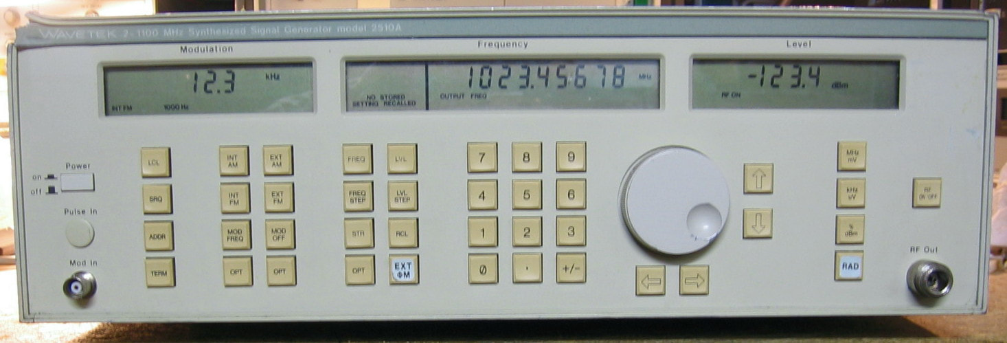
Wavetek 2510A: Synthesized RF signal generator, 0.2 to 1100 MHz. Wavetek is best known for function generators, but over the years dabbled in pieces outside their area of expertise. Such is found in the 2510A and the 2520A (which adds a doubler to 2200 MHz). The specs are approximately equal to HP's low end 8656B signal generator, but the Wavetek has an actual tuning knob and who doesn't love that? The display is LCD, not LED, and even with the anemic backlight, is not very readable in different lighting conditions. The buttonology is adequate (and the keyboard has a nice click to the buttons), but Wavetek did a few curious things in the firmware that had me scratching my head even after confirming everything in the user manual. The "autocal" is a nice feature that aligns all the oscillators and lets the user make output power adjustments at about 30 points. All in all, probably as good as Wavetek is capable of, but somewhat laughable if you are an HP RF engineer. ($CD) Grade: B+
The seller said the unit died after 10 seconds, so I took a chance at $50. I disconnected the load on the power supply and all the voltages were wrong. There was a burn mark on the Molex connector coming from the main transformer, so I cleaned that out. Still, the voltages were nuts and off I went into a several hour wild good chase. Bottom line was that despite my attempts to clean the Molex connector, it was intermittent. So rather than screw around, I cut off the connector and permanently wired the transformer to the P/S board. Everything then worked fine. The only other "modification" was to get rid of the key-lock used to switch the unit from normal to calibrate modes; this was replaced with a toggle switch.
Postscript: Fast forward a couple of years and the 2510A now displays an unlock message. The output frequency was tens of MHz away from what is dialed in and was unstable. After verifying that the internal/external reference switch on the back panel is set to internal, the service manual suggests trying the automatic frequency calibration; but all that did was immediately fail and issue an error message. There's a word for this kind of behavior: broken! The main loop in the 2510 uses a VCO that is mixed with a quadrature DDS pair and then divided down to the phase detector and loop filter. Seemingly, the DDS was outputting nearly zero which would tend to make the mixing quite bad. I substituted my own quadrature signals using the Wavetek 195 (poetic justice) and the 2510A suddenly worked perfectly. So now it was clear that the DDS circuitry was malfunctioning. It is basically done by stepping through (at different rates) a wavetable ROM containing a single sine wave. I pulled the ROM and read it and it looked correct, although the waveform is in the memory in groups of ten points, which is a bit odd. But in reality, it isn't odd if you realize that they are using BCD adders to step through the addresses and the BCD outputs only count from 0 to 9. The ROM outputs go to a D/A and the output of the D/A (through an op-amp) was completely wrong. My conclusion was that the ROM was not being addressed correctly. I hooked up my HP 1650A logic analyzer to the five 74HC583 BCD adders that generate the ROM addresses and found one that was faulty (stuck bits). I managed to find a cheap 74HCT583 on eBay and in it went. All fixed. Sounds easy in hindsight, but it took a few days to diagnose all of this. I also want to describe getting the main board out so I could remove and replace the chip. The main board sits next to the doubler control board and the two are wedged into the chassis. It is such a tight fit that you can see where the previous repairman had to punch a hole through the edge of the board with a screwdriver so he could pry the boards loose. While doing so, he managed to dislodge a 3-terminal regulator that was sitting perilously close to the chassis (it needs to be insulated). I fixed that problem and sanded the edges of the boards down a bit so they would fit back in without too much difficulty. A little more quality control from Wavetek would have been appreciated.
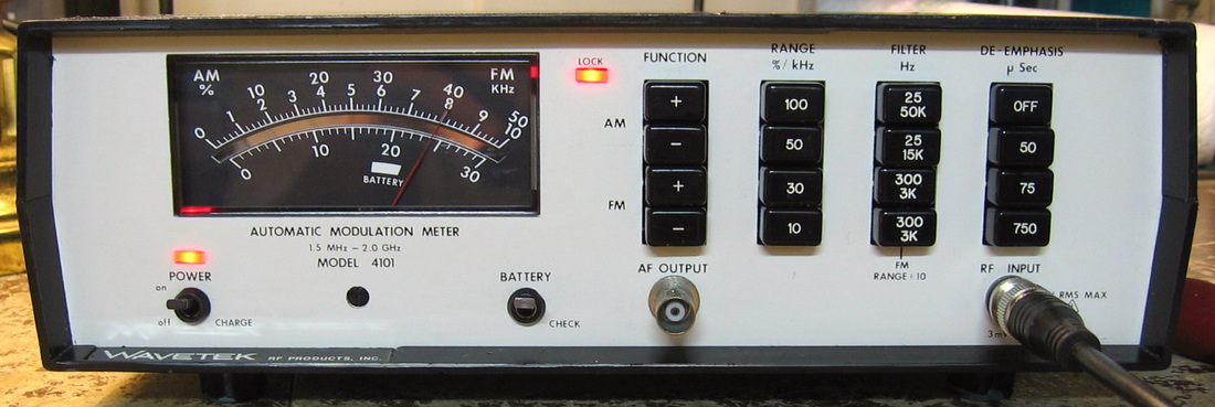
Wavetek 4101: Basic no frills modulation meter covering 1.5 MHz to 2 GHz. Will measure peak and trough FM deviation to 100 kHz and AM modulation to 100%. Has a few selections for audio filtering and FM de-emphasis. Wavetek bought the RF board from a Korean manufacturer; the exact same board can be found in several other modulation meters from reputable test equipment manufacturers. Despite all the potential drawbacks, it actually is exquisitely accurate and agrees with my gold standard HP 8901A to within about 0.5% everywhere I've tried it. (OEM) Grade: B+
Not responsive to any input when I received it. The input terminating resistors had been burnt to a crisp, so that's your first clue Sherlock. It was a simple matter to check the parts along the signal path until the end of the carnage had been reached. In this case, it was only the terminating resistors, two of the four diodes in the mixer and the FET buffer. At least it wasn't as bad as the Boonton 82AD.
Not responsive to any input when I received it. The input terminating resistors had been burnt to a crisp, so that's your first clue Sherlock. It was a simple matter to check the parts along the signal path until the end of the carnage had been reached. In this case, it was only the terminating resistors, two of the four diodes in the mixer and the FET buffer. At least it wasn't as bad as the Boonton 82AD.
Z :
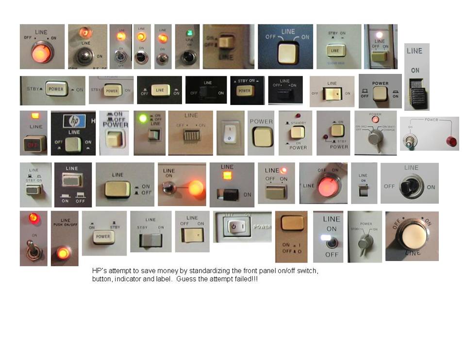
No, I don't have any equipment beginning with a Z. But if you've made it this far, you deserve a reward! I haven't updated this picture in a while and there are probably a couple of more rows of switch pictures I could add. But you get the point.
DISPOSED STUFF
People always ask, "Do you ever sell anything?" Occasionally I do, but I generally hate to part with something that I've fixed and has a story behind it. But here are a few that I have disposed of....

Berkeley Nucleonics 7010: This pair was dirt cheap, and I needed another pulse generator like I needed another cardiac stent. Does what it says - generates pairs of pulses with prescribed delays. Useful for someone I guess.
One worked, one didn't. Opened it up and found several mica capacitors rattling around. They simply were not soldered to the board. The holes in the board were perfectly clean. It was manufactured that way I guess.
One worked, one didn't. Opened it up and found several mica capacitors rattling around. They simply were not soldered to the board. The holes in the board were perfectly clean. It was manufactured that way I guess.
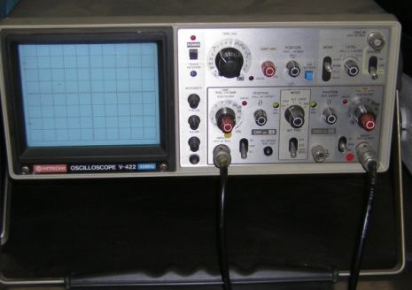
Hitachi V422: Basic two channel, 40 MHz analog scope. I forgot I even had this (stock photo off of web). Don't have it anymore, so I must have sold it many years ago. As I recall, other than dirty switches, the scope worked fine.

HP 1720A: The first piece of test equipment I ever bought on eBay. For $50, I opened the box and had a perfectly working scope. That hooked me. The rest is history (or the rest of this web page).

HP 5314A: Basic counter to 100 MHz. And when I say "basic," I'm being generous. This was one of those c.a. 1990 pieces where HP decided to compete in the "cheap" market. Fortunately, the competition didn't last long and HP seemingly went back to state-of-the-art stuff. The HP 5314A is a single-chip, non-interpolating, direct-count unit that is, for the lack of a better word, atrocious. I sold it soon after I received it.

HP 6205B: Dual power supply, selectable ranges of 20V @ 600mA or 40 V @ 300mA. Unlike some of HP's other multi-channel units, the two supplies in this piece cannot autotrack. Pretty basic linear power supply design, but why must they put the binding posts in "+ GND -" order so that I can't use a standard banana plug? I mean I could always strap minus to ground and make this a non-floating supply; then the banana plug would fit. Seems to me it would be a lot nicer to have the posts as "+ - GND". I'm almost tempted to rewire them like that (although the front panel markings would be wrong). Nothing wrong with it, I simply gave it as a gift to my son who is using it to anodize titanium jewelry.
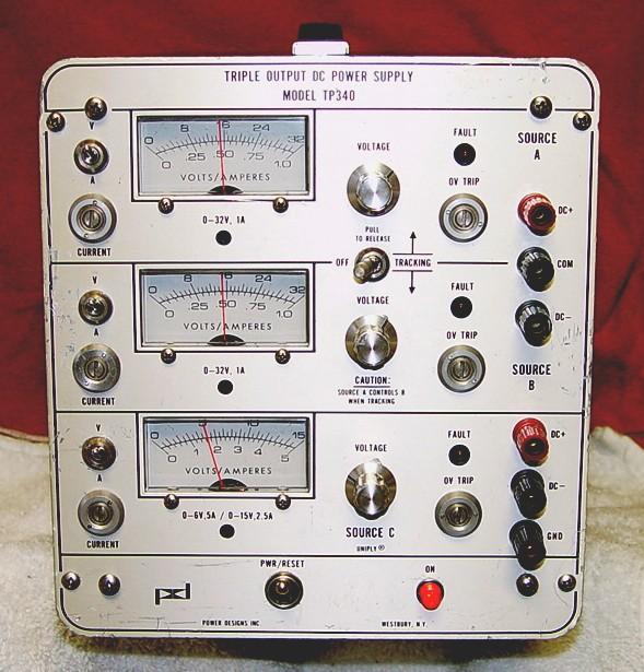
Power Designs TP340: A triple output power supply similar to the TP343B listed above. Power Designs made these rock solid supplies for many years and they are still considered among the best. This particular model does 32V at 1A on the top two supplies and 15V at 2.5A (with more current at lower voltages) on the bottom supply. Full metering, dual-tracking, settable overvoltage and overcurrent protection.
This was bought as a gift, so I never actually worked on it. The seller intimated that it functioned giving the excuse that the cal stickers across the case were still intact. However, he claimed that the three voltage pots were noisy and/or hard to turn. The recipient of this unit reported back the work it took to restore the piece to original: 1) four new rubber feet, 2) three new LED holders, 3) three new voltage 10-turn pots, 4) three V/A toggle switches and 5) minor mechanical work.
This was bought as a gift, so I never actually worked on it. The seller intimated that it functioned giving the excuse that the cal stickers across the case were still intact. However, he claimed that the three voltage pots were noisy and/or hard to turn. The recipient of this unit reported back the work it took to restore the piece to original: 1) four new rubber feet, 2) three new LED holders, 3) three new voltage 10-turn pots, 4) three V/A toggle switches and 5) minor mechanical work.
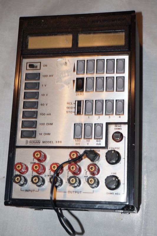
Ronan X86: Portable calibrator/generator for industrial applications. This odd piece both generates and measures volts, current and ohms with 4-1/2 digit resolution. The basic accuracy is on the order of 0.025%. Uses jacks that are not used in the test equipment field.
If I recall, I got two of these in a single buy. Sold one and kept the other. But at some point, I must have either gotten bored, or the thing broke, because I remember dissecting it. It was so long ago, I can't even find the boards I pulled out of it.
If I recall, I got two of these in a single buy. Sold one and kept the other. But at some point, I must have either gotten bored, or the thing broke, because I remember dissecting it. It was so long ago, I can't even find the boards I pulled out of it.
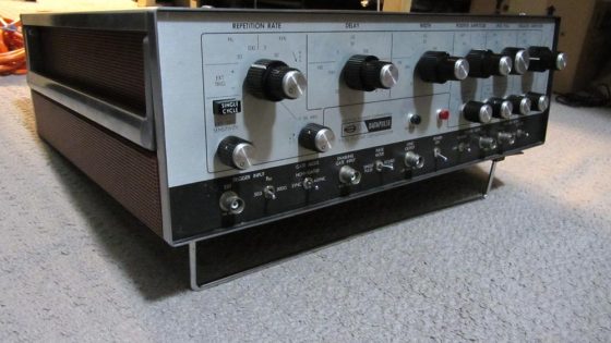
Systron Donner 110: Basic pulse generator. I bought this very early in my repair "career" and if I recall, it was thoroughly abysmal. I'm not even sure if I had the 110 or a slightly different variant, so I used a stock 110 photo here. The construction was terrible and the boards were done with inverse traces; in other words, about 95% of the boards were exposed metal. I donated this piece to the lab where I used to work. Not that they needed an old pulse generator, but it soothed my conscience when somehow a $20 gizmo in their lab that I needed for a repair mysteriously found its way to my lab at home. Don't have a clue how that happened!
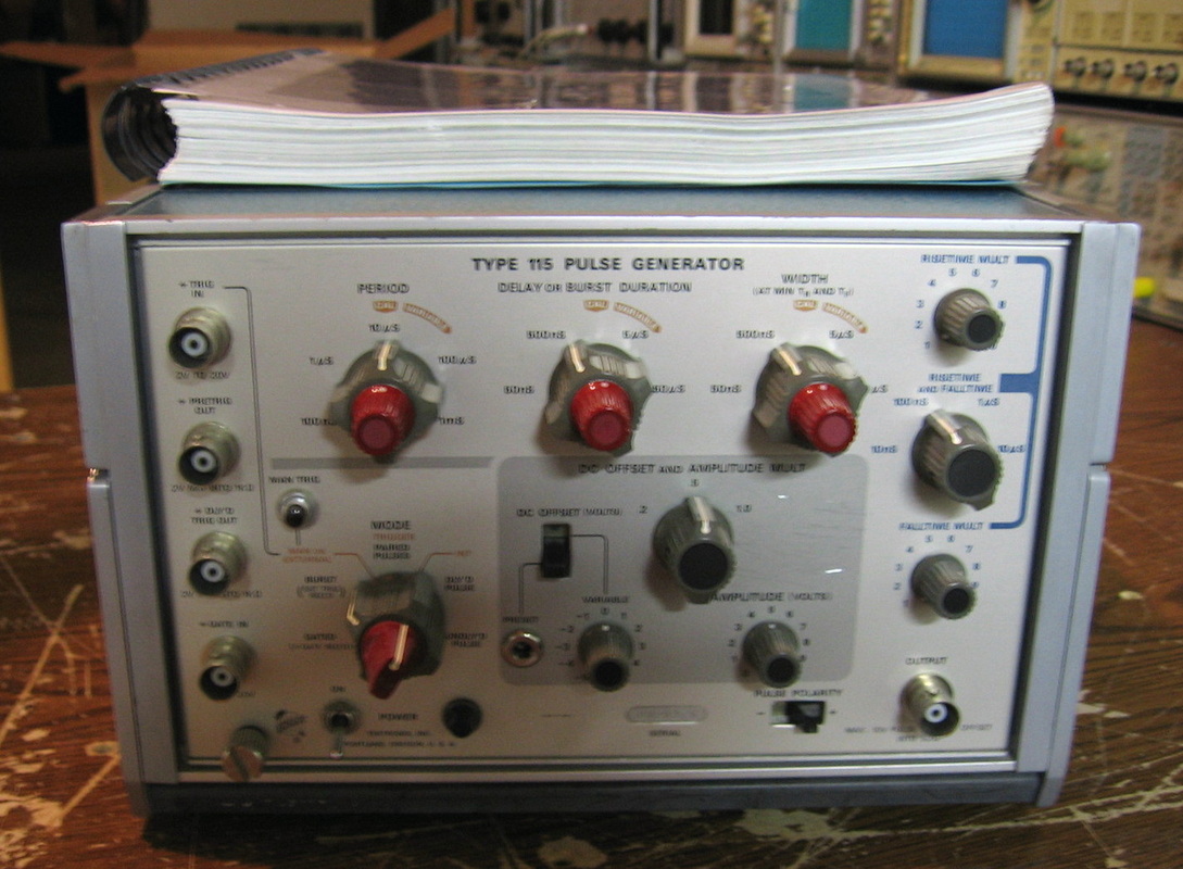
Tektronix 115: General purpose 50 MHz pulse generator. Duplicates plenty of others that I have. Hope someone could use it.
Had a bad transistor. I didn't have the right one, so I just kept popping in junkbox transistors until the thing worked at 50 MHz.
Had a bad transistor. I didn't have the right one, so I just kept popping in junkbox transistors until the thing worked at 50 MHz.
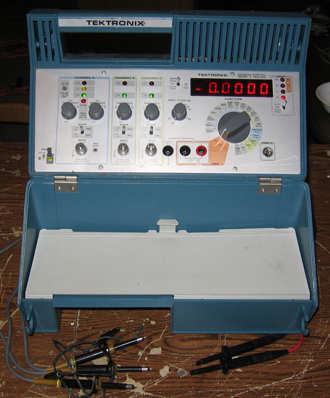
Tektronix 851: See the Systron Donner Versatester. This must have been designed by the same person. What were they thinking? I've read that it was used by field technicians who were simply told to "set the knob to here, make sure the reading is 4.0, etc."

Tektronix 2213A: Your basic Tektronix two channel 60 MHz scope. Does everything perfectly fine, just as you'd expect from a mid-1980 Tektronix model. The "A" model fixed some P/S issues in the original 2213 and added some more triggering options. My biggest complaint is the lack of graticule illumination. This piece was donated by a retired colleague (Dan) and came with Tek P6122 and P6112 100 MHz x10 probes. A colleague at work was looking to experiment with electronics and needed a starter scope. So I donated the 2213A to him.
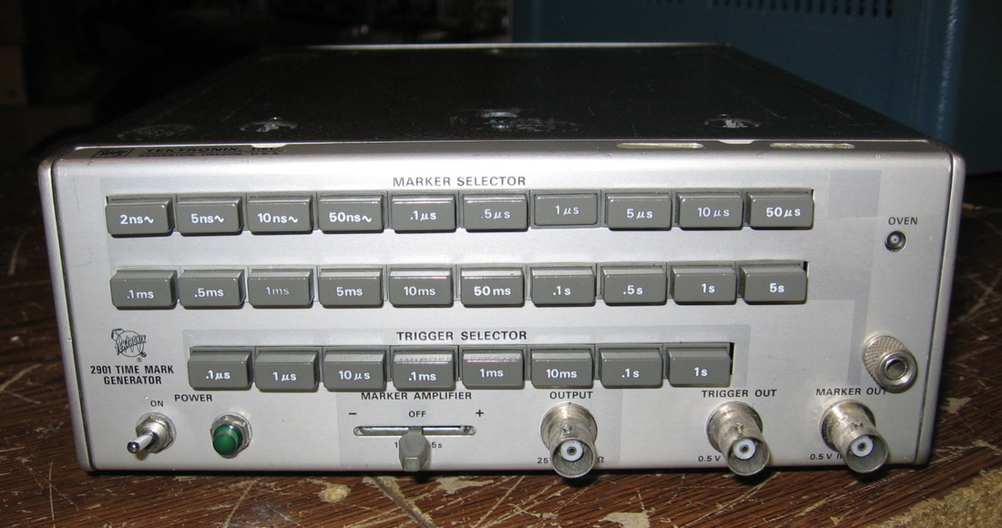
Tektronix 2901: A time mark generator that is pointless if you have an HP 5359A.
This was one of the worst offenders in the "Tektronix parts corrode in their socket" category. Reseated everything.
This was one of the worst offenders in the "Tektronix parts corrode in their socket" category. Reseated everything.

IT'S DEAD JIM STUFF
Well, you can't win them all, and neither can I. There have been a few utter disasters that I will describe below. I don't have my own pictures in some cases, so I used stock photos from the web.
Well, you can't win them all, and neither can I. There have been a few utter disasters that I will describe below. I don't have my own pictures in some cases, so I used stock photos from the web.
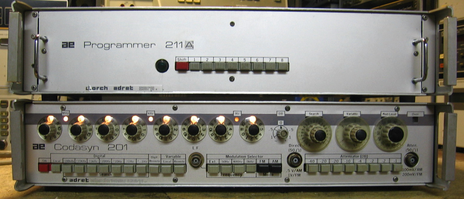
Adret 201/211A: 2 MHz synthesizer with remote control. Now this is one strange beast! The "Codasyn" 201 is a 2 MHz synthesizer with 0.1 Hz resolution and amplitude from 0 dBm to -100 dBm in 1 dB steps. It also does FM and AM modulation with a selection of modulation frequencies and FM deviations. A look at the picture reveals that the front panel is somewhat mysterious. That's because this unit has several (odd) ways of controlling the frequency. Normally, one just uses the 8 frequency knobs to dial in the frequency. But there is also a "search" knob that will vary the frequency around the dialed-in one by an amount whose range is given by the buttons on the lower left. Moreover, there is a "Variable" knob that can quickly slew the synthesizer across the entire 2 MHz range. All quite strange! But the basic synthesizer seems very good - an ovenized oscillator and harmonics 50 dB down from the fundamental. The companion 211A unit allows one to "program" eight specific frequencies and then push one of the eight buttons on the panel to command the synthesizer. The synthesizer architecture is the somewhat classic approach of using a variable frequency oscillator in a "digitally" controlled PLL for each digit and then summing everything up. Built in 1968 by the French, these two pieces obviously differ from your usual HP/Tektronix construction techniques to say the least. However, the $5 price was right, giving this piece a very high button-to-dollar ratio! (PDF) Grade: B+
These pieces came in condition unknown. The eBay listing photo showed that the power cord was included which was a good thing since the line socket is a custom connector. But what was very nice is that the seller also included the connecting cable between the two units and the op/service manual - in English (the available on-line manuals are in French). Upon initial power-up, the unit mostly worked, except the 1 kHz knob and 0.1 Hz knob were giving me erroneous readings. By swapping boards, I determined that the problem was on the boards, not in any circuitry involving the actual rotary switches. From there, I entered the Twilight Zone. For instance, I thought I found a bad transistor that decodes the frequency switch. I replaced the transistor with a 2N3904 and that made things worse. Then I replaced the 7490 divider that the transistor feeds and it was even worse than that. Then I put everything back the way it was and suddenly everything worked. This kind of thing happened on both the 1 kHz and 0.1 Hz boards - I have no conclusive explanation. As far as the 211A remote box, that seemed to work fine for all digits except the 0.1 Hz where it wasn't changing on odd numbers. Since really all the 211A does is parallel a second set of rotary switches into the synthesizer's rotary switches (with isolation diodes), my conclusion was that the interface cable might be faulty. I buzzed the cable and found two open pins. But then again, I don't have the schematic for the interface and perhaps those pins aren't used. But when I opened up one of the connectors, there were two wires flapping in the breeze. I soldered them back and everything now works properly.
Postscript: One day, I turned on this piece and the 1 kHz knob was only working for even numbered digits. Having seen this before, I made the same mistake and tried a 2N3904 on the decode path of the knob. Not surprisingly, it didn't correct the problem. The transistor I need is marked TS3011, somewhat baffling me. That's what I need according to the schematics (and the 1966 date code). The parts list, however, shows a 2N2369 switching transistor so I ordered a few of these. But while I was waiting for the transistors to arrive, the 201 suddenly stopped working entirely when the 0.1 Hz knob was used. Then it stopped working when I pressed the "local" button. Then the "variable" knob stopped working. Finally, the whole piece stopped working and only outputs 1 VDC regardless of any knob/button setting. The manual is available, but it is in French. The schematics, while OK for each individual board, fail to show all the interconnects clearly, leaving one completely befuddled. This, and the fact that most of the parts carry 1966 to 1968 date codes (and may or may not have suitable modern replacements) and the board connectors can't utilize standard extender boards, forced me to relegate this piece to the "It's dead Jim" pile. Unfortunate, because when it did work, it wasn't too bad.
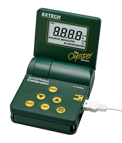
Extech Oyster Calibrator: Model 412355a voltage/current calibrator and meter. This is an odd piece that will measure voltage to 20 V, current to 50 mA, and will source voltage to 20 V and current to 24 mA. The basic accuracy is 0.075% + 1 digit. Runs on a 9V battery and has 5 memory registers. (PDF) Grade: B
Advertised as for parts or repair, I bought a lot of four of these units for $50 and I got burned real bad. First of all, I didn't notice that the jacks for test leads are a weird proprietary gizmo and the proper test lead cable is, of course, unobtainable. OK, I can always gin something up. But upon receipt, all four of these units were malfunctioning. Some of them would only power up when I disconnected and reconnected the battery. Some would power up correctly with a press the power button. Some would measure V but not A, some would source V and A correctly but not measure V or A, and vice versa. Bottom line is that none of them work fully. They are all surface mount parts and use an 80 pin microprocessor with built in A/D and current source whose pin spacings are so small, I couldn't even probe them without shorting adjacent pins. With a complete lack of a schematic, these four units were simply thrown in the garbage. But the seller did include a nice wall-wart with adjustable output voltages worth about $10. So I only got burned for about $40 I reckon.
Advertised as for parts or repair, I bought a lot of four of these units for $50 and I got burned real bad. First of all, I didn't notice that the jacks for test leads are a weird proprietary gizmo and the proper test lead cable is, of course, unobtainable. OK, I can always gin something up. But upon receipt, all four of these units were malfunctioning. Some of them would only power up when I disconnected and reconnected the battery. Some would power up correctly with a press the power button. Some would measure V but not A, some would source V and A correctly but not measure V or A, and vice versa. Bottom line is that none of them work fully. They are all surface mount parts and use an 80 pin microprocessor with built in A/D and current source whose pin spacings are so small, I couldn't even probe them without shorting adjacent pins. With a complete lack of a schematic, these four units were simply thrown in the garbage. But the seller did include a nice wall-wart with adjustable output voltages worth about $10. So I only got burned for about $40 I reckon.
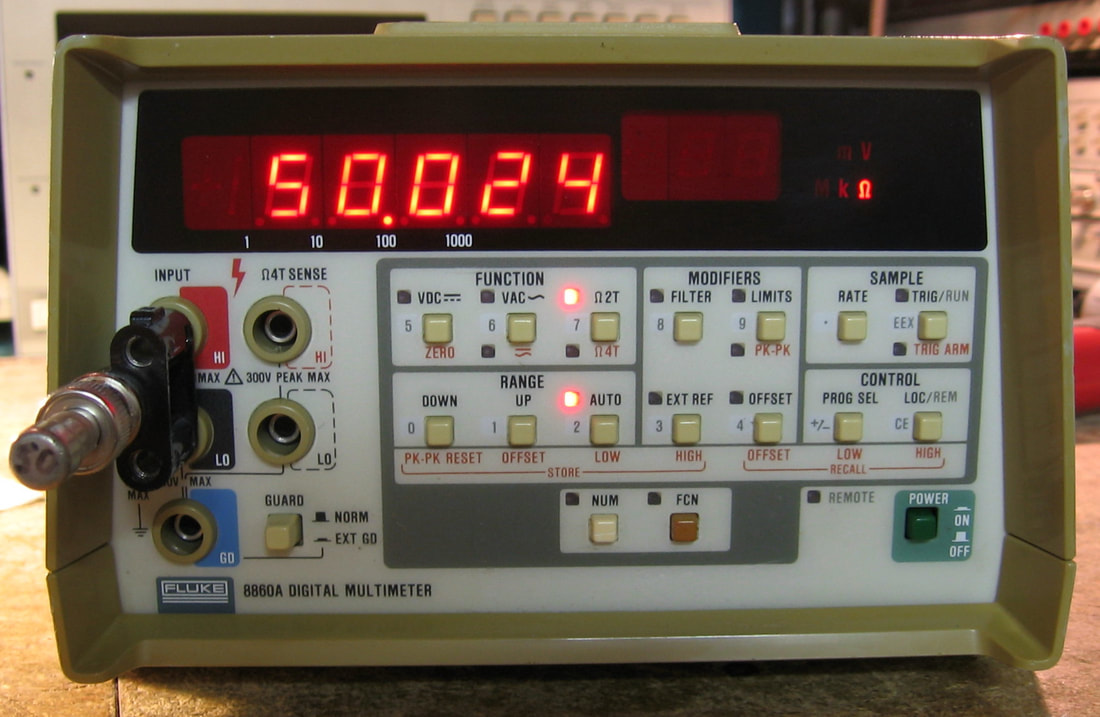
Fluke 8860A: Basic 5-1/2 digit DMM with VDC, VAC and ohms, nothing particularly special, but straightforward and pleasant to use. It's kind of cute and matches my Fluke 8921A (see below). Best case DCV accuracy of 0.004%. Fluke chose to put the calibration procedures in a separate manual which I had to shell out seven bucks for (boo). (PDF) (OM) Grade: B+
Advertised as broken and it certainly was - only the VDC function worked. Fluke did not use unobtanium hybrid ICs in this thing. No, they used unobtanium hybrid resistor packs and unobtanium hybrid FET switching circuits. The FET circuits are a ceramic substrate with embedded resistors and a bunch of FETs sitting on top. It sort of looks like the amplifiers in the Tek TDS scopes. One of the resistor packs was faulty and this was making VAC totally wrong. I patched around things with discrete resistors and problem was cured with VAC. I would worry about temperature stability, but the whole DMM only draws about 10 watts, so nothing is going to heat up inside. Ohms, on the other hand, was putting out too much current, so that everything read high and by the time you put more than 10K across it, the thing would overload. I spent a weekend checking everything around the FET hybrid module and my worst fears were realized as it looked like there was no other conclusion than a bad hybrid. Fluke only gives a functional block diagram of the hybrid, so I took a guess on the resistor values and FET parts and decided to build a replacement board for the hybrid module. A buddy at work produced the Gerber files for me and I procured the board from Oshpark for less than $10 (see picture below). Problem solved.
Postscript: One day I noticed that all of the measurements were very noisy. I proved that the culprit was the signal conditioner, not the A/D. Since there are three Fluke hybrid daughterboards in the unit, and two of them had already blown (and were fixed/replaced), I suspected the third. But before I got to check that, the whole unit locked up and became unresponsive. The outguard uP was running at 230 deg F, so that's no good! I replaced the uP, the associated P8243 expander IC and the 74LS373 address latch (shorted), but to no avail. Further investigation shows that the addresses to the program ROM are cycling through the same 10 instructions. When I pulled the ROM and put it on the reader, it was clear that the first two bits of the ROM were stuck at 1 for all memory locations. The piece truly is dead, Jim! I kept the piece around for a while hoping to find another one cheap, or some replacement ROM code, but no luck. Given that even if I could replace the ROM, there still is an analog fault (the original problem I was trying to diagnose before the digital side crapped out), the best course of action was to strip it for parts.
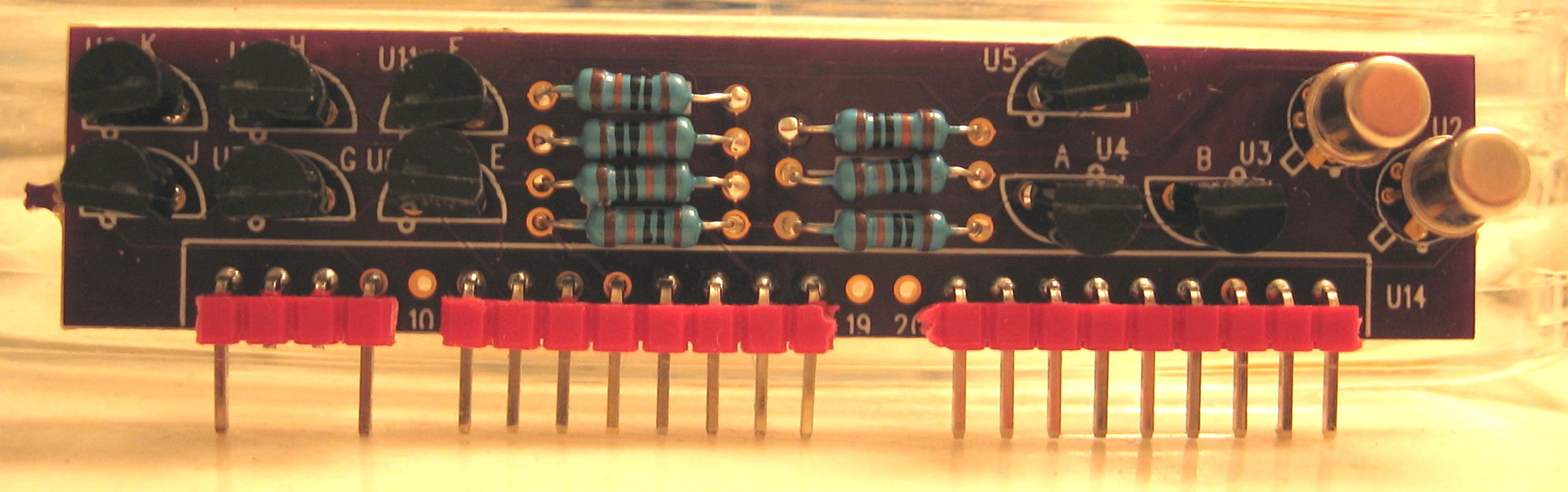
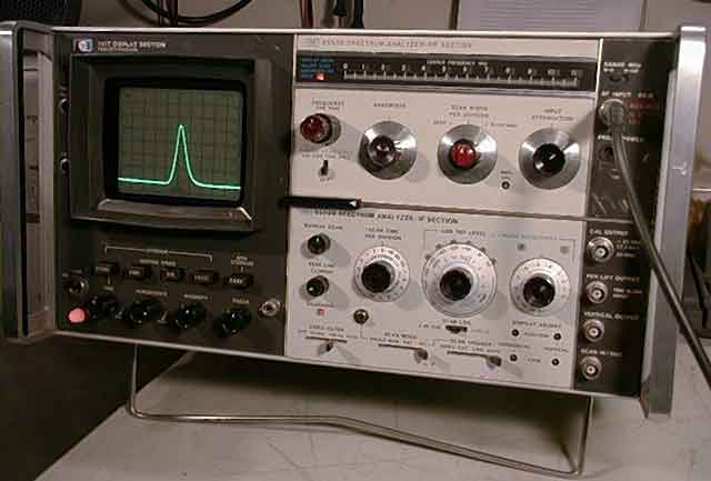
HP 141T/8553B/8552B: The HP 141T is a mainframe variable persistence display that was often populated with RF and IF plug-ins to produce a very capable spectrum analyzer 40 years ago. I made the mistake of buying this from an eBay listing with a catalog photo, not the photo of the actual unit. I knew as I pressed the button on the computer that I was making a mistake, since when a seller isn't willing to show the actual piece, warning sirens should go off. As I recall, I paid about $200 for it. Surprisingly, the outside of the unit wasn't bad at all - it certainly could have had a picture. It was when I took the covers off that I found the surprise. There were remnants of a mouse nest, and the mouse must have gotten hungry at one point, because he (or she) chewed up virtually every wire inside. To make a long story short, I sold off the 8553B and 8552A plug-ins for about $150, so I wasn't burned too badly.

HP 410C: This was a very popular VOM in the sixties and seventies. Originally using high voltage neon bulbs and photodetectors to create a chopper amplifier (with vacuum tube), it eventually evolved into an all-transistor version with a dual-FET. Two of these came with the purchase of an HP 4328A milliohmmeter. The first one was missing all three circuit boards inside and the second one was missing two circuit boards and the remaining board was burnt to a crisp. I'll get some cabinet parts, lots of screws/nuts, some fuse holders, knobs and two really nice 89 Mohm 1% resistors which I can test with my HP 4329A megaohmmeter.

HP 3400A: This AC RMS voltmeter came along in the same buy with two HP 410C VOMs, an HP 435A power meter and an HP 4328A milliohmmeter. See the description above for the disposition on the HP 410Cs. When I turned this HP 3400A on, the meter pegged and stayed that way on all ranges. When I took off the cover to take a look, I saw a board floating inside with a cut coax cable. So I opened up my existing working HP 3400A to see where the coax cable should go. Only then did I see the real problem. Someone had removed the whole back end of the range switch (wafers and resistors). So this piece will serve as spare parts for the working one should the need ever arise.
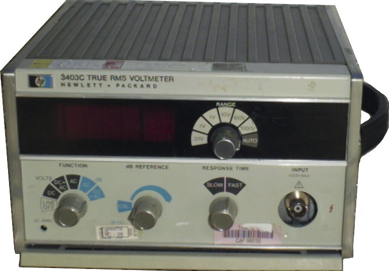
HP 3403C: This is a very nice true RMS digital AC voltmeter. It would have been even nicer had the thermocouple inside not been burned up. And this is despite HP putting in a protection circuit to prevent just that. My guess is that the protection circuit failed shortly before someone overloaded the input. Note that there are dozens of 3403Cs listed on eBay, all showing pictures of nicely powered up units with nothing attached to the input. I wouldn't buy one of these unless I saw it being fed with a signal generator. Anyway, with no chance of getting a replacement thermocouple, this piece is now a source of spare components.

HP 3551A: Advertised as a transmission test set, all I really wanted were a few knobs and buttons. I got this for a few bucks, took off the parts I needed, and am now using it for other spare parts. It has a lot of the old metal can op-amps, for instance. I don't know if it worked when I got it - I didn't even turn it on.
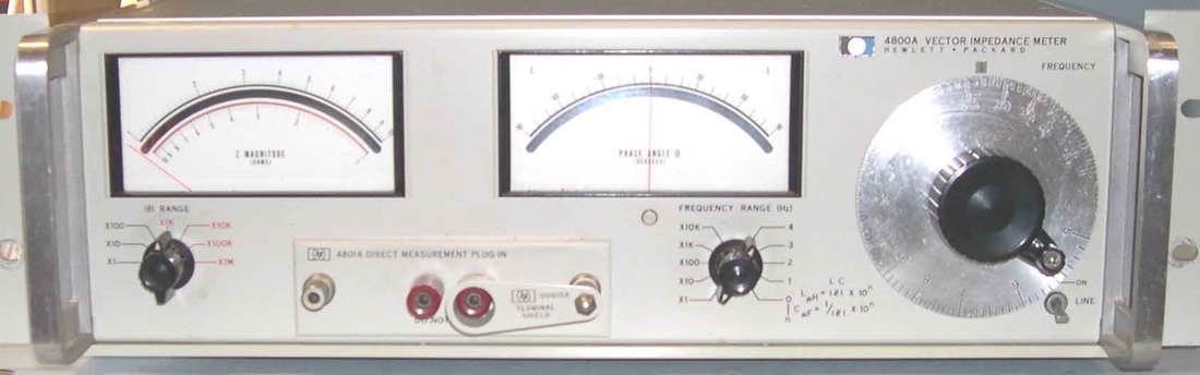
HP 4800A: Low frequency (500 kHz) vector impedance (0 to 10 Mohms) meter. I don't exactly know which version I got because the impedance range knob wouldn't turn to the last three ranges. When I dissected the switch, there was a stop purposely put in there. I removed the stop, but whoever put it in really wanted it to be there, because the parts required to make the thing work on the last three ranges were absent. So I was really bummed out, because even if I could fix the thing, it is only half of the capability it should be. The sealed lamp unit used in the feedback circuitry of the oscillator was burned out as was the lamp for the photodetector in the AGC circuit. Rumor has it you can fix the oscillator lamps, but the photodector is a bit more dicey. I spent two days trying to get the thing to work properly with an external oscillator and a lamp shining at the photodetector (after I sawed the sealed unit in half) and then gave up. So I pulled out all the useful parts and threw the chassis away. Probably got $20 worth of parts: knobs, pots, and about 100 2N3904/6s. Oh, and a couple of very nice 5M and 50M precision resistors.
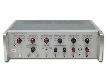
HP 8005A: One of HP's mid-range pulse generators, this piece was simply beyond repair. All the circuit boards suffered from the most corrosion I've ever seen in a piece of test equipment. Was this thing left out in the jungle or something? Would have been a total waste of money, but it does have lots of 1 and 2 watt resistors to scavenge.
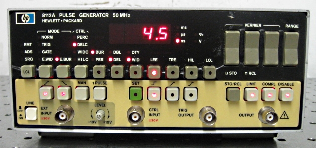
HP 8112A: A quite nice 50 MHz pulse generator, I took a chance on this one and lost big time. It was advertised by a non-test equipment dealer as not powering up. Usually, all this means is that the seller plugged it in and didn't see it light up. A real test equipment dealer would have at least spent 15 minutes on it. Anyway, it came in absolutely filthy condition with a lot of very poor rework already done on the power supply. After I replaced the blown fuse, it drew about 3A (lucky I put in a larger fuse!). While I was mulling this over, I noticed that the front panel was completely screwed up. Every single one of the buttons was mushy without the characteristic click. So now it is going to require a rework to the P/S and the front panel. Ugh. The 8112A uses five custom HP hybrid chips (which of course can only be obtained from another unit) and these are buried on the third of three stacked boards. When I pulled out the first two boards to look at them, there were five very nice EMPTY 24 pin sockets where the hybrids belong. Can you say death sentence? I spent about $60+shipping and if I am very lucky, I might get about $20 worth of parts out of it after I strip it bare. As Dirty Harry says, "a man's gotta know his own limitations."
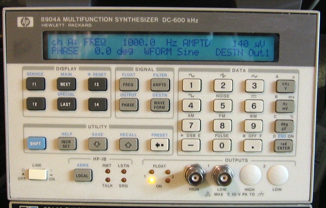
HP 8904A: Very capable 600 kHz function generator with lots of (optional) configurations. The battery inside had leaked and destroyed a section of the board, burning traces and components beyond recognition. Normally this would not have been a problem - merely a tedious task of careful reconstruction. But HP decided that their design was "proprietary" and purposely did NOT include the details of this board in the service manual. Shame on them. Portions of this dead unit (display board and output board) were later used to repair my current HP 8904A.
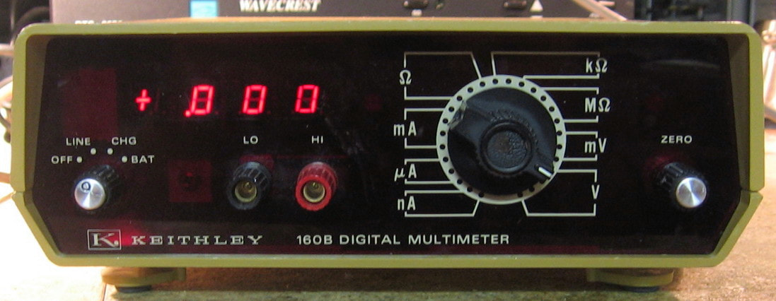
Keithley 160B: 3-1/2 digit DMM doing DCV, DCI and ohms. What initially intrigued me about this $30 piece was the very wide input range: 1mV to 1000V, 10nA to 1A and 1 ohm to 1000 Mohms. However, once you get by the feeling of being impressed, you quickly find out just how abysmal this piece truly is. It's bad enough that the accuracies are about 0.1%, 0.2% and 0.3% for V, I and ohms, but the real kicker is the lack of auto-ranging. You have one giant range select knob and for reasons known only to Keithley, the sub-ranges are not marked. Why? And since you will be twiddling the knob thousands of times, you would have thought Keithley would have at least put in a high quality switch. Think again. I don't know what Keithley was thinking (maybe it was "geez, let's build a piece of crap that can compete with other manufacturer's pieces of crap"). Hopefully, the designers of this piece got fired! OK, let me be fair - hopefully the managers that directed the (probably faultless) designers got fired! Keithley should be ashamed of themselves given their usual high quality offerings.
The seller intimated that the range switch was dirty, so I took a chance that I could clean it. However, as remarked above, the range switch is a low-quality piece of junk and several of the contacts were bent or chopped off. I managed to dissect the six-wafer switch and get it all working - barely. I wouldn't expect my repairs to last too long, however. This piece also had extensive repairs at one time (many of the op-amps and transistors had been replaced) by someone with little talent as he/she managed to lift a bunch of traces and had to bodge together jumpers.
Postscript: I was cleaning out the front panel banana connectors and suddenly the whole red plastic window shattered into a bunch of little pieces just like tempered glass. I therefore relegated this (working) piece to the "It's dead, Jim" pile. But before that, I stripped out quite a few useful parts including a bunch of 0.1% tolerance, low temperature-coefficient resistors.
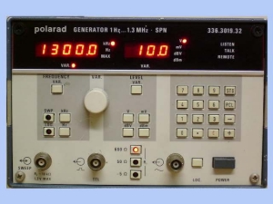
Polarad SPN: This is a cute story! Polarad is essentially Rohde & Schwarz and the SPN is a 1.3 MHz signal generator. Upon power up, it is supposed to welcome you in German, then go to the default settings. Mine just sat there with strange alphanumerics. While I was thinking this over, someone in Florida saw that I won it on eBay and wrote to me saying that he had a close variant of the SPN and was trying to fix his also. He knew that the output board on his piece was the same as mine and he wanted me to take a few voltage readings. I didn't have service manual for the SPN, but the Florida guy did and promptly mailed me a hard copy. While I was making measurements for him, I determined that the program ROMs in my SPN were hosed. Unfortunately, I couldn't ask the Florida guy for a copy of his ROMs, because he didn't have the exact same unit. So I took out the output board and sent it to him as thanks for sending me the manual. He wrote a week later saying that my output board fixed his unit and he was a happy camper. And then he said that he only enjoys fixing the stuff and really has no use for it. So he offered simply to send me his fixed signal generator for free! I thanked him, but declined the offer. So let me understand, the guy just likes to fix stuff regardless of whether or not he has a use for it? Remind you of anyone?
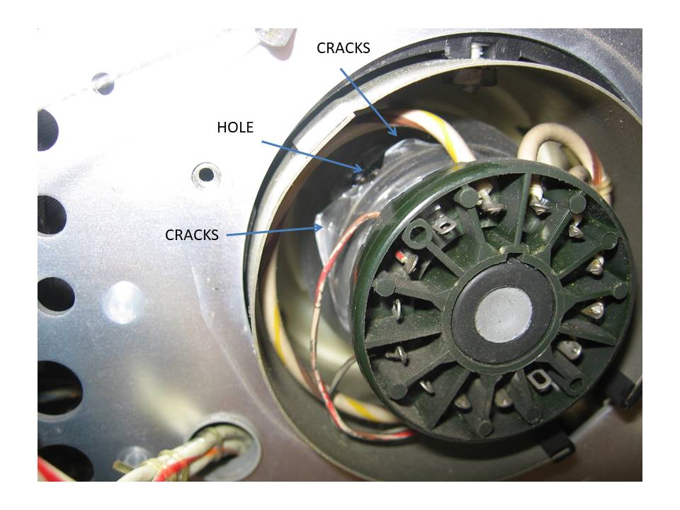
Tektronix 475: Although I have a perfectly good Tektronix 466 100 MHz storage scope, I thought I would try the 200 MHz non-storage scope also. Big mistake. Advertised as dead and not powering up, I figured maybe it was a shorted tantalum on one of the power rails, as the Tek 400 series is noted for that. But the seller lied, because when I received it, the 475 powered right up and all the P/S voltages were fine. But the CRT showed no trace. Had the seller said that the scope powered up, but there was no trace, I probably wouldn't have taken the chance. The HV to the tube was fine, so I pulled off the back cover so I could see at least if the tube was glowing. It was not, and as the photo shows, that was pretty much the end of it. I stripped the thing down and now have a whole bunch of Tektronix replacement parts. It was only $40, so I didn't get burned too badly.
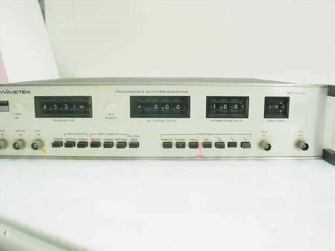
Wavetek 154: This is supposed to be a 10 MHz function generator pretty much like every other 10 MHz function generator. The controls are done by front panel numeric thumbwheel switches and there is a "digital" port on the back panel that allows an operator to mimic the settings. When received, the power supplies all checked out, but the output was fixed at about 17V. As I probed further into the unit, the amplitude controls didn't work, the offset controls didn't work, the waveforms (as observed on the fixed square wave output on the back panel) disappeared after the leading frequency digit was set higher than 5, the attenuator relays weren't switching correctly, and on and on. I spent an entire weekend debugging the 154 and found two bad transistors and a shorted capacitor in the output amplifier. Unfortunately, this didn't fix a single problem. And the manual is atrocious. Certain lines end in a number that refers to a connection on the mother board. Yet that motherboard connection appears nowhere else. Perhaps I have some missing pages in my manual. I've had several pieces designed around 1970 that use discrete transistors to achieve almost all of the functionality. Unfortunately, these transistors are either no longer obtainable or cost an exorbitant amount. The designs back then were so dodgy that you can't just substitute the ordinary 2N3904/6 and expect it to work. It's almost like the designers barely managed to get things to work with hand-selected transistors of a certain type and beta. I've had this problem on a few pieces from that time frame, mostly Fluke pieces, that I ultimately was never able to fix. Obviously, the Wavetek 154 doesn't have any functionality that I don't already have (x10), so I will strip it down for parts. Maybe the next time I am stupid enough to buy a piece like this, I'll have a source of replacement parts.
Miscellaneous: I'm sure I've left something out because I have a lot more parts and circuit boards sitting around under the benches that had to come from somewhere...
GENERAL REPAIR NOTES
I've been on this repair kick for a few years now, so here are a few words of wisdom in no particular order of importance.
- Before you even plug a piece in, do the following: 1) Check the fuse for continuity and proper rating (you'd be surprised how many previous owners put the wrong fuse in); 2) Check the line voltage switches (if there are any) for a setting of 110/120 VAC (or whatever is right for your location); 3) Shake the piece vigorously and listen for things rattling around (happens more than you would think); 4) Take the covers off, reseat all the boards you can easily get to, and do a quick visual survey, looking for loose cables, burnt parts, etc. Now you can plug it in (via your isolation transformer). I like to get under my bench and reach up, so if and when the piece explodes, I don't get hit by the shrapnel!
- Power supply failures account for a majority of problems. Use a scope to measure the AC ripple on all P/S outputs. 60 Hz ripple points to a diode problem, 120 Hz ripple points to a capacitor problem. Short of those two failures, a pass transistor is likely gone. There are occasionally other problems such as failures of the regulator circuit or protection circuit (Zener and/or SCR) but they are rare. ALWAYS, ALWAYS, ALWAYS check the P/S as the first step in ANY repair. In fact, even if you turn a piece on and it appears to work correctly, check the P/S.
- I would say mechanical failures out-number electrical failures by 5-to-1. Mechanical failures include switches, pots, relays, cables and connectors. You can include IC and transistor sockets, too. Always, always look for mechanical failures first. Then reach for the voltmeter and scope. I have also found that pieces that have sat dormant for years sometimes act up when first powered up again. Often this can be remedied by reseating the boards and connectors. I think years sitting in my cold damp basement causes contact degradation.
- Have a good in-circuit transistor tester. You can get by with an ohmmeter, but a real transistor checker makes quick work of things. I have found that the in-circuit testers have about a 90% accuracy; they can be fooled sometimes, for instance, if there are low shunt resistors in the circuit. As a last resort, one can always pull the transistor out-of-circuit. The same thing goes for in-circuit capacitor testers.
- Aging electrolytics are your enemy. They will be way low in value and ineffective (open or nearly so) or shorted. I've hardly ever seen anything other than those two cases. A high ESR on an otherwise OK electrolytic is a nice theoretical concept, but I've only seen it once or twice. Sometimes you get lucky and the cap is leaking goo or has left white powder residue. Your biggest problem is that the modern replacement electrolytics are half the size of the old ones. But that's a happy problem to have.
- Let's talk about leaking electrolytic capacitors. Not the tantalum variety which generally explode, but the ordinary aluminum electrolytics (surface mount or through-hole) that often leak goo. The smell is quite recognizable and sometimes the leak is confined to underneath the cap so there is nothing visible. However, if you hit the pins with a soldering iron, you will smell it. The worst case, of course, is when the electrolyte migrates all over the board. This can cause havoc with a piece, even corroding IC pins and traces. Early Tektronix TDS oscilloscopes are a prime example of this carnage. When you have such a situation, it is imperative that you scrub the board clean. I use Simple Green with a toothbrush and a gentle water rinse, followed by some "air drying" via my compressor. Do it a few times - lather, rinse, repeat!
- I've recently had quite a few tantalum capacitors go bad, mainly shortly after starting up a piece that has been sitting unused for months, if not years. I guess these capacitors degrade over time (moisture?) and the initial shock of voltage can pop them. Moreover, manufacturers usually ran the caps nearly at the max voltage rating - 16V tantalums were extremely common on 15V power rails. 99% of the time, the tantalum capacitors fail in a short (or a near short of a couple of ohms) and 99% of the time, there is some outward sign like discolorations, burn marks, dimples, cracks. Sometimes you are lucky and they explode or catch fire. But I've had some recently that went short with absolutely no visual indication. Usually these things are hung off of the power rails and I simply replace them with electrolytics since they are not that critical.
- Rifa Capacitor Bonus Rant: Let's talk about AC line suppression capacitors. Most of my equipment falls into one of the following three categories: 1) no AC filtering (the AC socket goes through a fuse, on/off switch to the primary of the transformer); 2) sealed line filter (usually a small box containing the fuse and the filters with no serviceable parts); 3) discrete suppression capacitors and/or inductors. It is the third case that is the problem, especially when these components are ahead of the on/off switch and hence are active whenever the piece is plugged in (and even worse - sometimes the capacitors are ahead of the fuse!). Among these discrete parts, the gold-colored Rifa capacitors are notorious for blowing up. They should be replaced on sight regardless of apparent condition. I've had a few blow up and the stench is terrible, not to mention the goo that gets sprayed all around. This is why I have a master kill switch in my lab that cuts power to all of my outlets and why I throw it at the end of every day. Although none of my exploding Rifa caps have started a fire, why take a chance. HP was fond of using Rifa caps in the 1980s and I am currently going through my pieces looking for them. For instance, my HP 8080A has six of them!!! The Rifa "problem" is even worse in Europe where the 240 VAC is close to the rated voltage of the cap, unlike here in the USA where it is only half of that. Replacing these caps can be very difficult, especially in the most dangerous case where they are mounted directly on the backside of the AC power receptacle. Many manufacturers rivet the receptacle to the back panel and then surround it with so much stuff, you have pull the entire back panel off just to get to it. This often leads to an hour or so of nervous disassembly and reassembly. At the time of this writing, I have replaced 64 of the Rifas. It is usually the X-capacitors that go bad and are in the worst condition if they haven't already blown up. I don't think I've ever had a Y-capacitor blow up.
- Always look for signs of previous repairs. There's a good chance that the previous repairman screwed it up. Even if he didn't screw it up, many times it will lead you to the area of the circuit that may still have problems.
- Pray that there aren't any backup batteries in the piece. If there are, they will have leaked. Pray that they didn't leak all over the board. Pray that the leakage didn't cause a fire and destroy half of the board before you got the piece (that has happened to me). Because many of my pieces sit idle for long periods of time, I often replace rechargeable NiCd RAM backup batteries with a pair of AA or AAA batteries with a series Schottky diode in an enclosed plastic holder. That way, when they eventually leak, the goo is contained. Rumor has it that Duracell batteries are the worst leakers. I concur.
- A scope can be used to look for faulty TTL/CMOS devices. You can often just probe around looking for a logic level that is floating between high and low. But a logic analyzer is the way to go. You don't need anything flashy. A simple 8 channel timing mode logic analyzer can spot bad chips in a flash.
- Always attempt a calibration/adjustment when you think you have repaired a piece. A failure to properly calibrate is a pretty good warning sign that something is still wrong.
- When calibrating/adjusting a piece, always mark the pots/caps/inductors etc. before you start turning things. That way when you find you have screwed something up, you can go back. Some pieces (e.g., Tektronix) have elaborate adjustment sequences and you might find that ten steps later, you have gotten the thing so badly adjusted, it is dysfunctional. Trust me on this one.
- Always be suspicious of op-amps when their outputs measure at or near to the voltage rails. Unless it is an open-collector comparator, something is probably wrong. Look at the two op-amp inputs also - they should be very close in voltage.
- Be careful when checking diodes. For instance, you can have an open diode in a (discrete) four diode bridge in a power supply. One diode can be open, but the diode check will always pass (since there are paths through the other diodes and transformer). Get out the desolder gun and lift one end. Of course you can't lift one end of an encapsulated diode bridge. All you can do is check for equal resistance in each direction for each half of the bridge. Check with a scope to see that there's no ripple on one side due to an open diode. Also, occasionally you'll find high voltage (low current) diodes in circuitry feeding a CRT. Since these are internally comprised of several lower voltage diodes in series, an ordinary multi-meter will show them to be open. Indeed, the multi-meter does not supply enough voltage to forward bias the diode series. In that case, you can remove the suspect diode and use a high voltage power supply through a current limiting resistor to see if they will conduct. Or if you have a current source like my HP 6177C, you can use that (since the compliance is >50 volts).
- Think about the consequences of some idiot putting several hundred volts into any one of the many (unfused) input jacks (including the ones on the back panel). That should get you started with a lot of repairs. Occasionally that same idiot might hook his cable of death to an output jack, but he usually isn't quite that dumb. This is a common occurrence, for instance, with modulation or power meters.
- Tighten every screw you can find - board mounting screws, back panel screws, frame screws, transformer screws, fan cover screws, doesn't matter. They will all be loose. For those truly suffering from obsessive-compulsive-disorder, you might want to gently push every single capacitor so that it is exactly perpendicular to the board or de-solder and flip any resistors whose color codes aren't aligned left-to-right.
- HP pieces in the 1980's all used the front panel pushbuttons that give a little click. The click comes from a tiny leaf spring inside the actual switch. It is very common for these springs to come out of their mountings. I think it is a poor design on HP's part, because the springs dig into the plastic housing with about 0.000000001 inch of plastic serving to retain them. You will know when the springs are dislodged because the button won't snap back (even though the switch will still work if you tap it lightly). So be very careful when dissecting an HP front panel. The spring may be loose in there somewhere. You do NOT want to lose the spring as it is very difficult to manufacture one out of some piece of metal (rumored that the right metal is inside cheap RF-ID tags you find in department stores).
- Everyone has their favorite chemical for getting off sticker residue. I like Carb/Choke cleaner the best. Be very careful, however, as some chemicals can lift the paint off the front panel (try to test first in some inconspicuous area). Everyone has their favorite chemical for cleaning/lubricating switches, pots and edge connectors. I've tried two of the Caig De-Oxitproducts, but I always seem to keep coming back to good old Radio Shack tuner cleaner even though it leaves an unholy mess. Oh yes, do let the stuff dry before using the equipment.
- Be careful when adjusting pots (or anything else for that matter): 1) use a dedicated pot-adjusting tool, 2) put heat-shrink tubing over the shaft of any 1/8 inch or smaller screwdriver, 3) be careful about letting tools slip. Also be careful when using several pieces of equipment simultaneously to adjust your unit. It is easy to get confused and swap cables or leads which can ultimately lead to unintended shorts.
- Don't be afraid to retrace your steps. On one of my pieces, the microprocessor was locking up (unknown to me) because the RAM backup batteries had leaked and failed. Soon after I got the piece, I put new batteries in, but it did not cure the microprocessor problem, so I pulled the batteries back out. Turns out that there was some corrosion on the main board where the wiring from the batteries entered. After I cleaned up the corrosion surrounding those wires and other nearby parts, I didn't go back and reinstall the batteries, thinking that it had nothing to do with my locked-up microprocessor. I was wrong. Had I gone back and retraced my steps, I could have saved myself many hours of fruitless debug time.
- After you have fixed a power supply, look at the output on a scope - that's why you have a scope. There could be some funky high frequency (zero mean) oscillations going on that won't effect the DC reading on your DVM and are above your DVM's AC frequency response. The perfect DVM readings will lull you into a false sense of security.
- I guess this goes without saying, but I'll say it anyway: check the back panel. Many pieces, particularly signal generators, have switches on the back panel that exercise some control over the unit. In the case of a signal generator, there is often an "internal/external" reference oscillator switch. Guess what happens if the switch is set incorrectly? Also, if buying off an auction site, examine the pictures of the back panel carefully. I've picked up quite a few bargains where the seller claimed the piece was defective - I was able to see switches in the picture that were set wrong and at least gave a plausible explanation for the fault.
- When admiring your restorations, be mindful of the instrumentation you are using. A prime example is using a "good" oscilloscope to view the output of an older function generator. Many of these generators produce very high frequency noise, way above their specified frequency range. An oscilloscope with high bandwidth will see the noise; an older, lower frequency scope will not. Even more modern generators, like the HP 3325B and HP 3336C, produce junk several octaves above their upper frequency limit. And my very modern 40 MHz Wavetek 195 produces a -30 dBm, 10 MHz-wide FM signal at 600 MHz. Hook the Wavetek 195 up to my 500 MHz HP 54522A scope, turn the Wavetek amplitude down to 10 mV and good luck - false triggering, noise spikes, etc. Setting the BW limit on a scope usually cures all ills, but the simple message is that the manufacturers only seem to care about their specified frequency range and your instrumentation may be considerably wider.
- Sometimes a piece will be "close" to working. There are no overt power supply problems, but something is just not right. With the power off, you start checking the obvious, like shorted capacitors, open or shorted diodes, shorted transistors, but everything seems to check out fine. So, after a few hours of fiddling around with the power back on, you prepare yourself for a more thorough, disciplined debug session. And then ... voila, the piece suddenly appears to work fine. This has happened to me at least a half dozen times. The most likely explanation is that old capacitors needed some time to reform. But competing theories lead to tin whiskers burning off, The Force, God, or what have you. I think what I am trying to say is give a newly acquired vintage piece some time to be reborn. If the problem is truly old capacitors that need to reform, there is a recommended procedure where you slowly step-up the AC line voltage (through a Variac). But life is too short for that. I've also noticed recently that some of my pieces with switching power supplies fail to start after they have been sitting for a long period (years). But try power cycling a few times and they eventually start right up. Again, reforming caps???
- This is not so much a repair note as a safety warning. Having a lot of equipment, I run a lot of (cheap) power strips. The cheap ones have a tendency to lose the ground connections (and possibly hot or neutral) because the plug makes contact with the outlet by scraping along a thin piece of metal. The metal eventually bends out of the way. Do yourself a favor and put one ohmmeter lead on the chassis of one piece that is plugged in, and then put the other lead on every other chassis in turn- you should see a short (generally, nothing needs be powered on). If not, start looking at the power strips. Just open it up and gently compress the contacts on the outlets a bit.
- As mentioned in many of the repair notes, Sprague (electrolytic) capacitors are the worst - a true blight on the test equipment repair landscape. Now, perhaps they were the only game in town 40 years ago, but really? Also, when you are looking at a board of 1970-1980 TTL/CMOS logic, look for any chips with National Semiconductor markings. They are second only to Sprague capacitors in guaranteed problems. Uh, wait a moment - wasn't National Semiconductor essentially started by Peter Sprague? I rest my case. As far as Mr. Sprague goes, as Al Capone said in the movie, The Untouchables, " I want him DEAD! I want his family DEAD! I want his house burned to the GROUND!"
- Don't be afraid to study the schematics. I know it is tempting to dive right into a fresh piece with your voltmeter in one hand and your scope in the other. But I have fixed many pieces essentially "on paper" by first observing the symptoms of the fault and then consulting the schematics and circuit descriptions to figure out what component must be responsible. Obviously, this doesn't always work and there is a tradeoff between study time and poking-around time. But it is extremely satisfying to be able to point to a part, replace it, and have the piece fixed in a minute or two, after doing your homework.
- Here are a couple of warnings about IC sockets and used IC's. With a good de-soldering gun, one can generally remove DIP IC's intact. There may be some residual solder on the leads which normally isn't a problem except in two instances I've found. The first is when you try to use an IC tester having a ZIF socket. I have found that sometimes not all the leads will electrically connect to the tester because the solder on one or more leads prevents the ZIF socket from closing with adequate pressure. The second instance is the following: Whenever I pull an IC, I usually install an IC socket before putting a new chip back in. But what about putting the old IC back in? As before, the used IC may not make good contact with the socket. In other words, if you want to put a pulled DIP IC back, simply solder it back in. I've been burned by both of these instances (see the Tektronix T912 entry).
- I haven't discussed tools very much on this site. Besides all the hand tools such as pliers, cutters, screwdrivers, etc, I consider the following three tools the most useful things I own: 1) de-soldering gun, 2) electric screwdriver, and 3) small LED flashlight. For de-soldering, I've tried braid and hand-operated vacuum pumps. Although they work, nothing compares to a good de-soldering gun. I use the Hakko FR-301 ($275 street price). You do go through a fair number of tips and filters, so you can expect to spend another $25/year on maintenance. Sure, you can de-solder a 16-pin through-hole IC the hard way - I can do it in about 30 seconds. Plus, I don't destroy the chip I'm removing. Similarly, when you open up a typical HP piece and an inner cover with 40 screws is staring you in the face, you will be happy you have an electric screwdriver. Nothing fancy needed, although I do like the ones with a torque clutch. Something less than $50 will do fine. Finally, buy a small LED flashlight because lab lighting is never good enough to see way inside a piece. Spend about $20.
- With today's modern smartphones and tablets, it is really easy to snap a few pictures of a piece or a board that you are about to start repairing. For instance, I was given a small 10.5V, 5A switching power supply to repair that had popped its AC fuse. I had to desolder a few parts in order to isolate the short at the front end of the supply (two rectifiers). I replaced the fuse and the diodes and the supply came back to life. However, I was only getting about 9.5V and the output voltage dropped precipitously as soon as any load was placed on it. That led me on a weekend wild goose chase hunting down problems in the secondary. Turns out that the input voltage doubler had been disabled, so the supply was running at "half-speed" and could barely achieve its rated voltage open circuit. And why was the voltage doubler not working? Because the way the doubler is enabled is by shorting two solder landings on the board with a blob of solder. And when I was removing parts, my desolder gun happily removed this blob. It never occurred to me to short two landings when I put parts back - I mean, aren't solder shorts to be avoided normally? If I had snapped a photo before I started, I would have seen it. But I didn't and it took me a fair amount of head scratching to figure out how this power supply had ever worked in the first place.
- I've found it useful to have my Kindle sitting next to the piece under repair so I can have access to the service manual and also be able to download component information from the web. But the Kindle is so slow, I've grown frustrated and recently upgraded to an iPad. And I came across an app ($5.99) by Marcus Roskosch called "Electronic Toolbox." This has databases, formulas and pretty much everything you need while repairing a vintage piece. Get it - you won't be disappointed. Grade: A
SOME STATISTICS...
Knobs, buttons, switches, meters, displays,... Who doesn't love playing with these? On the theory that you can never have too much of a good thing, play with these:
- 9,062 front panel knobs, buttons, switches (and probably another 400 or so on the rear panel that weren't counted)
- 2,581 front panel LEDs
- 974 BNC jacks (and several hundred more on the back panels)
- 1,245 digits of numerical LED/LCD display
- 613 binding posts & banana plugs/jacks
- 59 incandescent & neon light bulbs
- 115 analog meters
- 56 CRTs
- 50 N-connectors (with N-BNC adapters - I don't particularly like N connectors unless I'm high up in frequency!)
- 4 TNC connectors
- 4 SO-239 connectors!
The latest catalog MSRP of this collection totals $2,192,585. That will roughly buy you:
- 87 DVM, VOM, AC Voltmeters, Ammeters, VTVMs
- 44 Signal Generators/Synthesizers
- 58 Function/Pulse Generators
- 11 Logic Analyzers (and variants)
- 37 Oscilloscopes
- 26 Receivers/Spectrum Analyzers/Network Analyzers
- 26 Power Supplies
- 35 Counters
- 40 Component Testers
- 24 Modulation/Audio/Transmission Analyzers
- 16 Calibrators
- 5 Tape Recorders and Associated Testers
- 25 Tek 7000-Series Plug-Ins
- 29 Uncategorized
- 2 Time Domain Reflectometers
I figure that if I were to stack all of the pieces on top of one another, it would reach to the 12th floor of the Empire State Building. Whew, only 90 more stories to go! The total weight is greater than one ton and if I ever were to turn everything on at once (not that I have enough outlets), I'm sure it would put a pretty good dent in my 200A house supply (actually, it would probably trip the main breaker).
Now I generally recommend with older equipment that you press every button, turn every knob, flick every switch once a week or so in order to keep the controls from freezing in position and causing problems later on (like I find in a lot of the stuff when I receive it). So go down to your lab and touch everything. What's that take you, a few minutes at best? With my collection of about 9,000 controls (front and back), it takes close to two hours!
KUDOS and FINAL REMARKS
With a collection this large, I have had ample opportunity to compare and contrast features and performance across many vendors. While I personally have preferences, I think I can provide a rough recommendation for anyone contemplating a purchase of a vintage piece. And here it is: Tektronix = Oscilloscopes, Fluke = Digital Multimeters (although they need careful adjustments to achieve good linearity), HP = Signal Generators and Spectrum Analyzers, Wavetek = Function Generators (definitely avoid any Wavetek pieces earlier than 1975 - they are mostly junk). Those should be your first choices, although obviously almost anything HP is a pretty good bet. Racal and Marconi devices offer generally good quality and the service manuals are, for the most part, obtainable. My experience with Racal, in particular, is a bit inconsistent - some of their stuff is excellent and some is rather poor. Keithley made some very good specialty equipment, such as their picoammeters, as well as a slew of DMMs of varying cost. Genrad and ESI make some fine component testers and resistance standards if you can find them cheap. Wandell-Goltermann makes exquisite gear, but they are aimed at the telco industry and do not have universal appeal (their service manuals are also tough to obtain). EIP (now Phase Matrix) makes very nice under-appreciated microwave counters. The Datron line of DMMs are also very nice, but could be a problem if the display ever fails. In addition to Fluke DMMs, Fluke has and continues to dominate the calibrator market (not that mere mortals can usually afford such things, or get them calibrated if they are so lucky as to stumble upon one). And Gigatronics makes some nice microwave signal generators I'm sure, but my experience with the one I have has been horrible. Brands that I would definitely stay away from, based on my limited experience, include Systron Donner, Krohn Hite and Ballantine. As this web page illustrates, there are plenty of offerings from companies not very well known. This, of course, is a hit-or-miss proposition - the biggest stumbling block is usually the lack of service information. On the other hand, these off-brands usually sell for peanuts, so if you are unsuccessful in your repairs, it's not the end of the world. Besides, one can usually strip a piece for parts and build up your junkbox.
If you have read this web page in its entirety, thanks and congratulations - you have an interest in vintage test equipment that rivals my own!
Perhaps some of the repair notes might even help you fix your stuff. Remember, use caution when working on equipment. I specifically shy away from vintage tube-type test equipment, because the voltages encountered are often quite dangerous. Similarly, working on or near CRTs make me cringe. But, as long as you are methodical and watch what you and your hands are doing, it really isn't hard fixing things. Remember, I have absolutely ZERO formal training in electronics - all my skills (if any) were acquired through experience. But, after fixing several hundred pieces, I guess I can claim I have A LOT of informal training in electronics!
Finally, thanks to Bob, WA1MIK (who passed away in June, 2021), for technical editing and his recitation of the immortal words...